Advanced Sheet Metal Design Using NX Cad Challenge_2_Box Assembly
BOX Assembly
Aim :
To Design the box assembly sheet metal as per the given dimension and model by using the various sheet metal tools in NX cad.
Objective :
- Design the main bottom part using the sheet metal tools.
- Design the top cover part using the sheet metal tools.
- Design the Side hinge part 1 at the main part using the sheet metal tools.
- Design the Side hinge part 2 at the Top cover part using the sheet metal tools.
Design approach :
main part :
Top cover :
Side hinge part 1 :
Side hinge part 2 :
Design Procedure :
Design the Bottom main part :
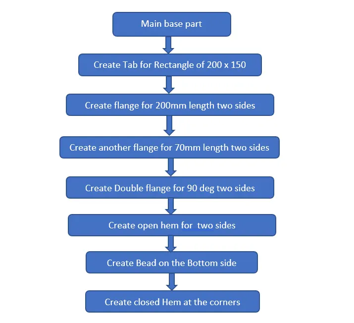
First create the required tab for 200 x 150mm and create the flanges for 200 at the two sides of the tab as shown in figure. And from that flange create other flange for 70mm and make closed corners also as shown in figure.
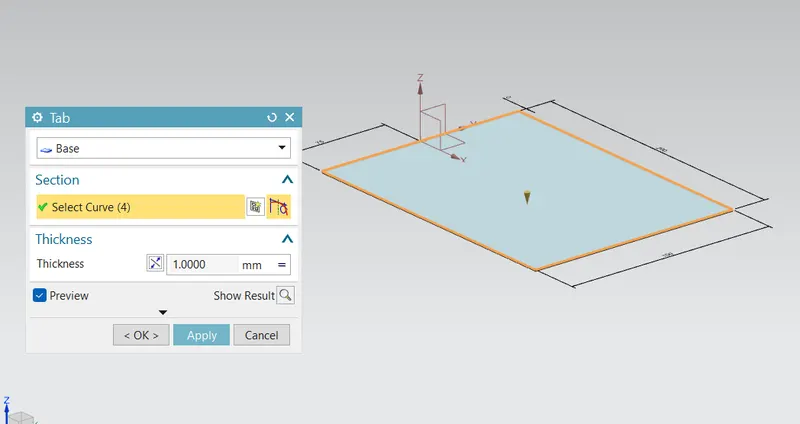
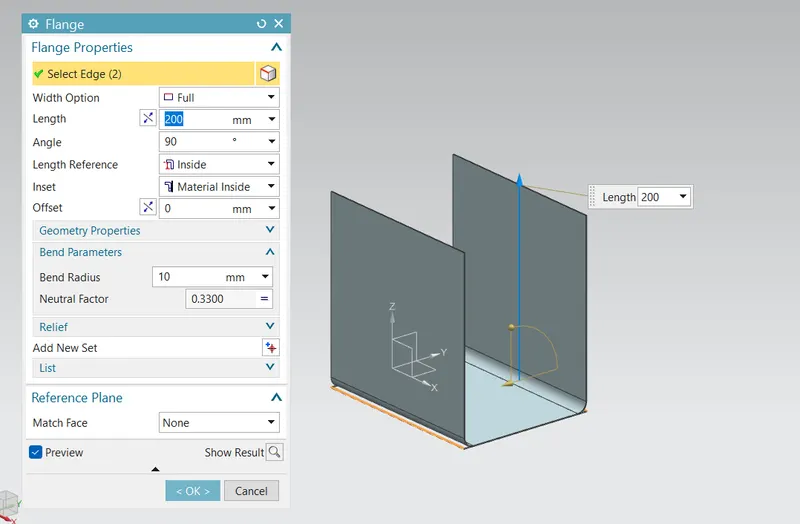
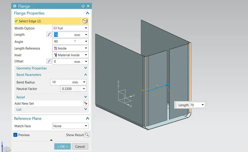
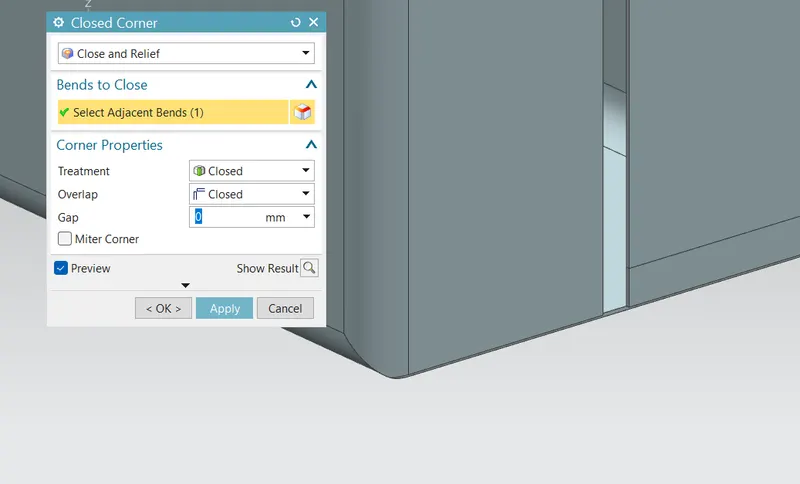
Then the gap between two flange is filled with the two flanges we created. and from the flange we create open hem at the flange end for the two side as shown in figure.
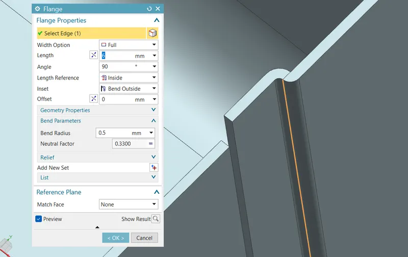
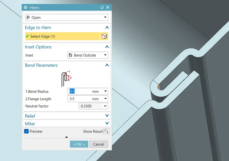
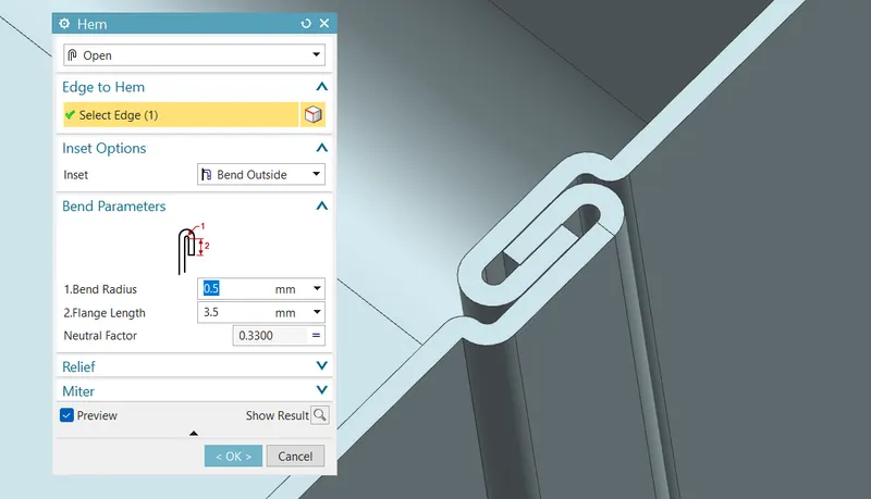
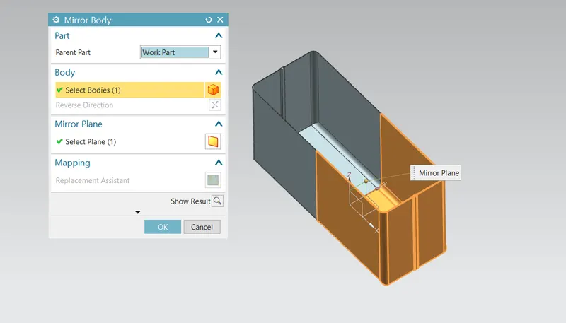
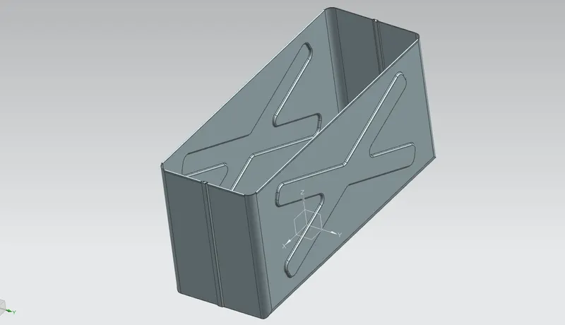
Then mirror the body with reference to the XY plane as shown in figure. And after the create the Dimple with the required sketch and create the Dimple and mirror the feature as shown in figure.
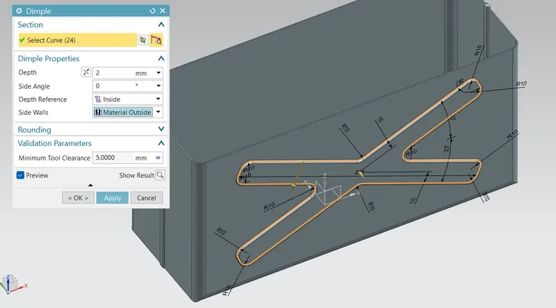
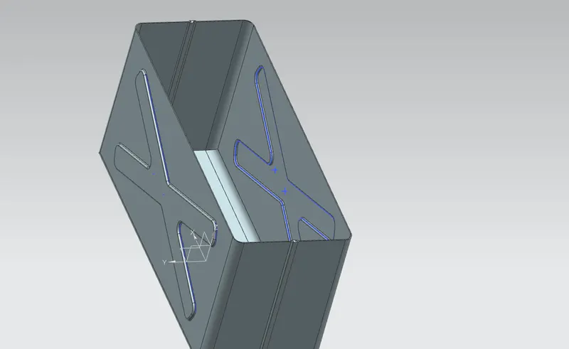
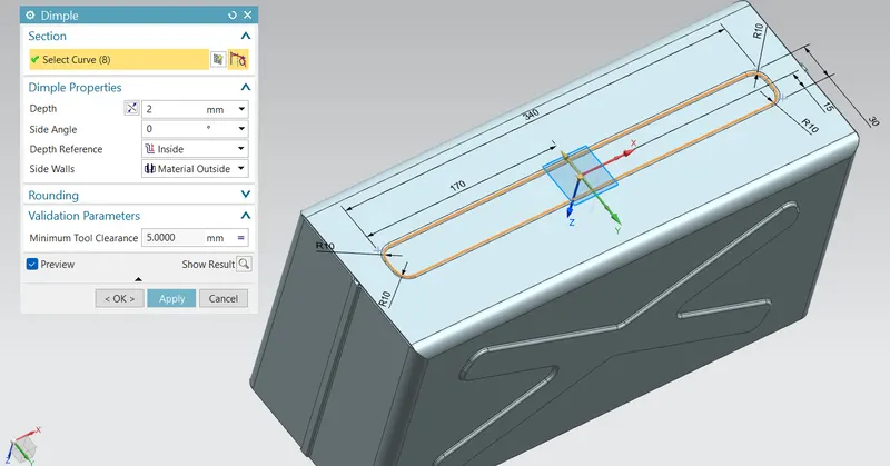
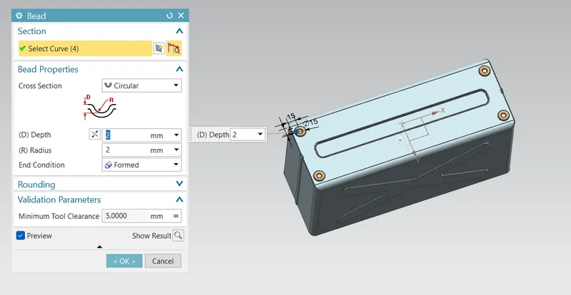
Similarly create the bottom side dimple with the sketch as shown in figure. and also create the Bead as shown in figure.
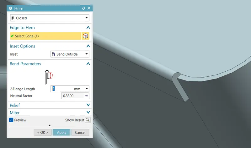
Finally create the hem at the all corners of the box as shown in figure.
Design the Top Cover :
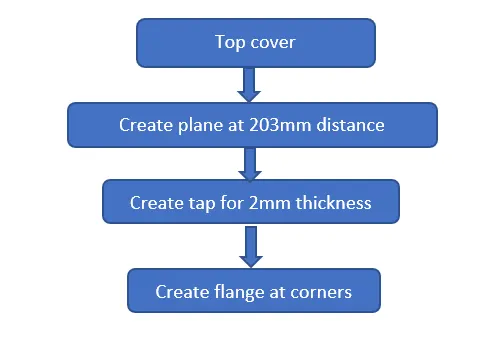
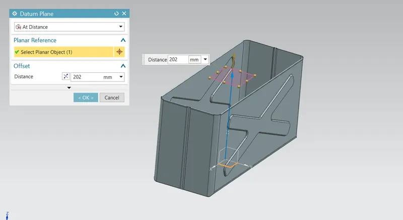
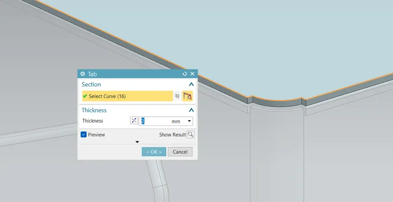
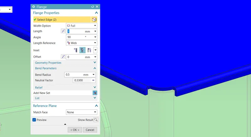
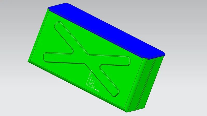
Then the next step is to create the top cover for the main part so need to create the plane at the top of the box part for 203mm distance. and create the required sketch at the plane and tab it for the 2mm thickness. and also create the flanges at the edge of the tab we created as shown in figure.
Side Hinge part 1 :
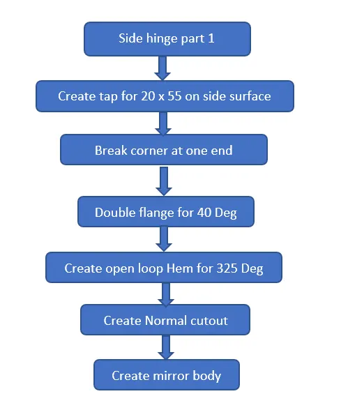
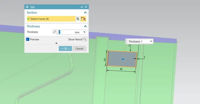
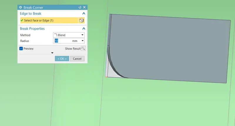
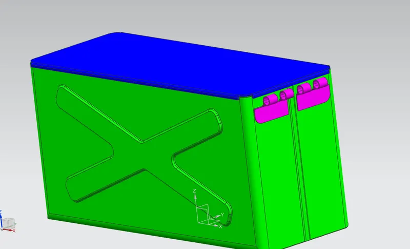
Next create the tab at the side of the box part for the 20x55 size. And create the break corner at the one edge of the tab we created and also create the double flange for 40Deg as shown in figure.
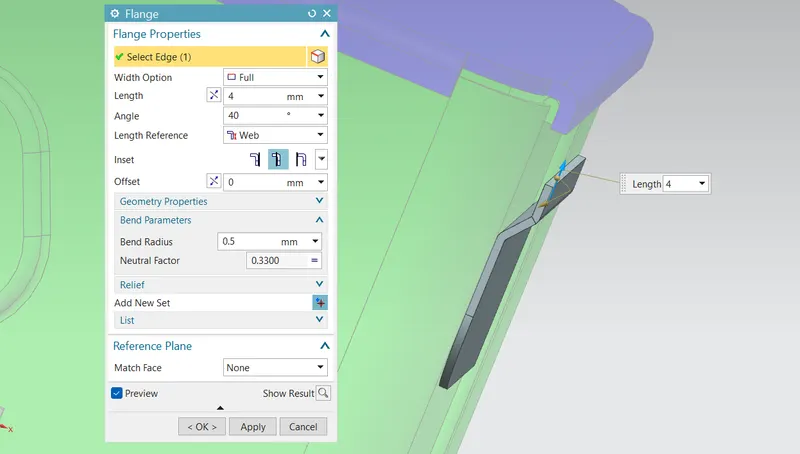
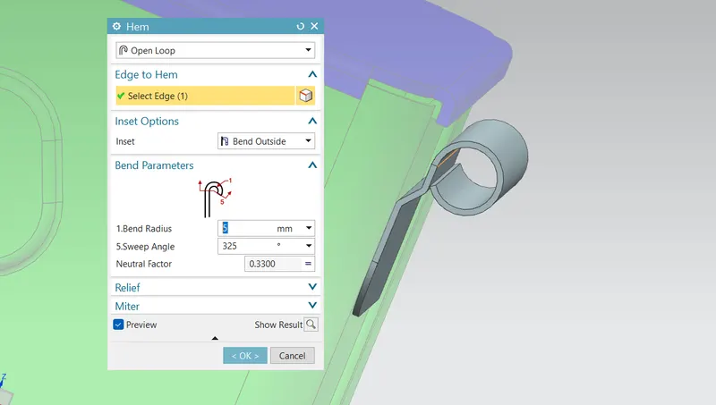
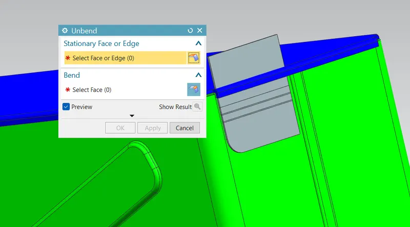
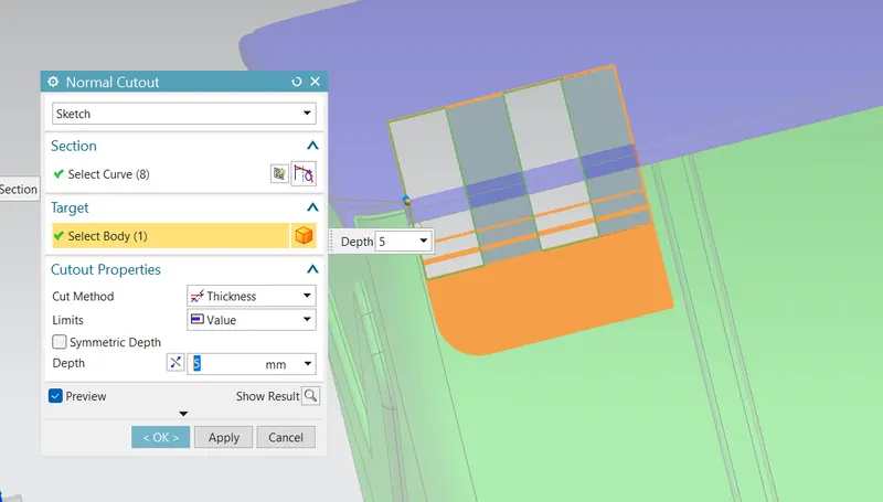
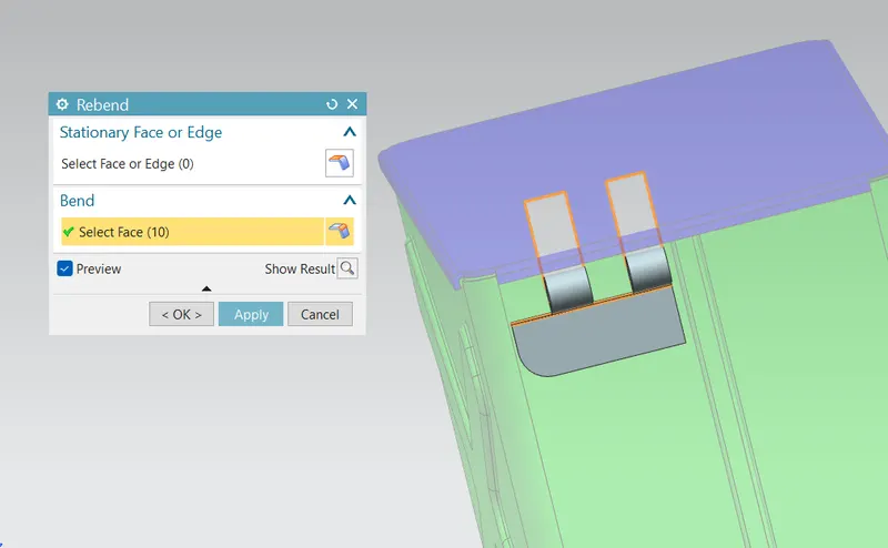
Then create the open loop hem for the 235 Deg with 5mm bend radius as shown in figure. and unbend the tab and make the required cutout and do the rebend as shown in figure.
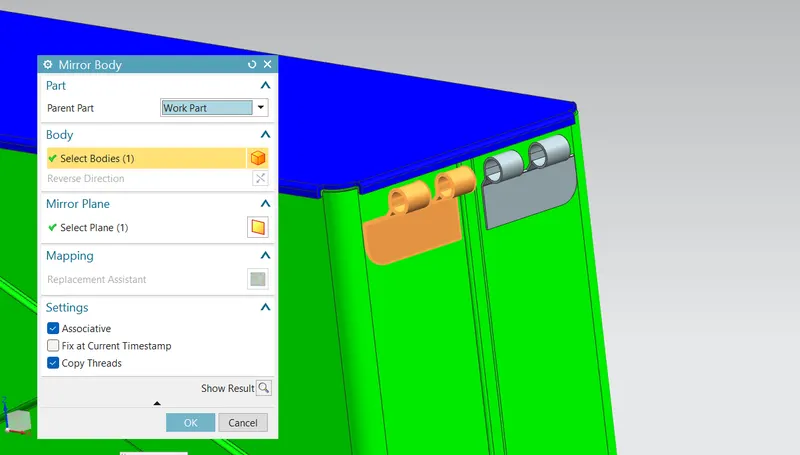
Then create the mirror feature by using the hinge we created as shown in figure.
Side Hinge part 2 :
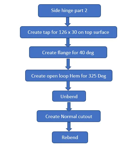
Next create the tab at the top of the box part for the 126x30 size. And create the break corner at the two edge of the tab we created and also create the flange for 40Deg as shown in figure. From the open loop hem for the 325 Deg as shown in figure.
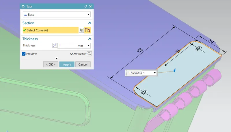
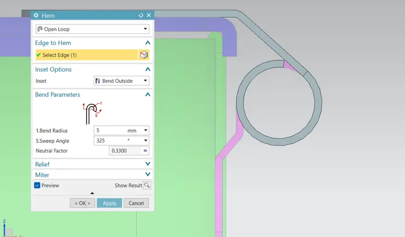
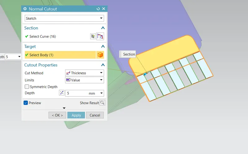
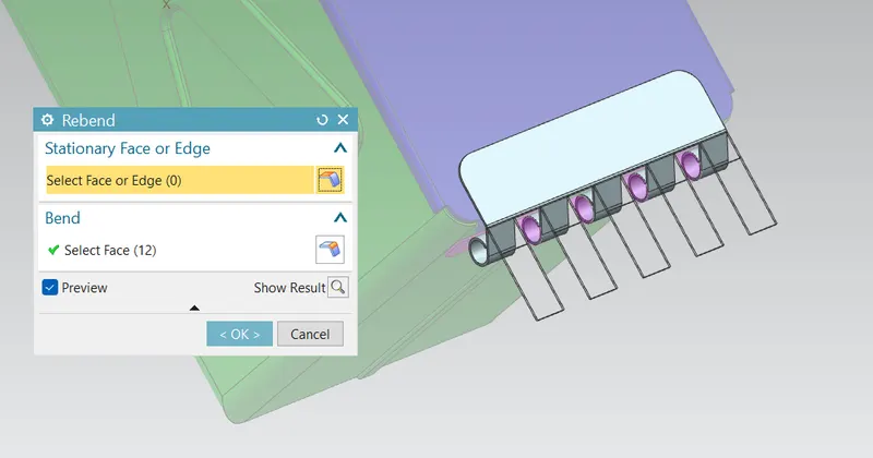
And next step is to create the cutout for merge with the hinge part 1 after create the cutout rebend the sheet metal as shown in figure.
Differnet views :
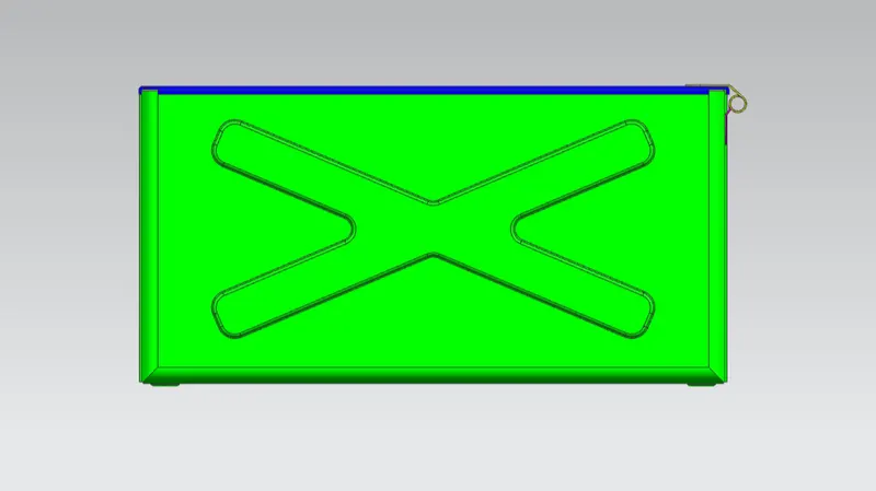
Front view :
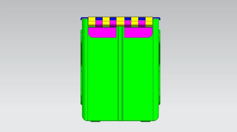
Side view :
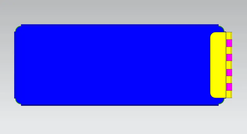
Top view :
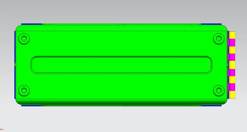
Bottom view :
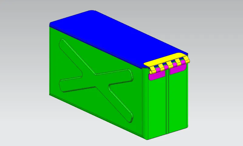
Iso-metric view :
Conclusion :
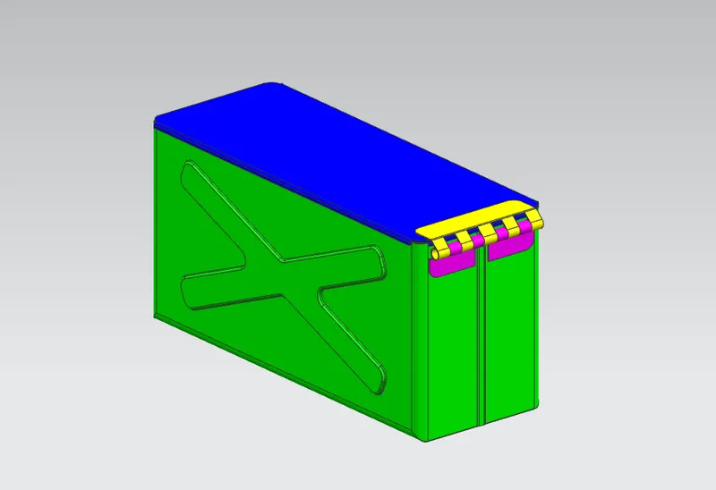
Hence the box assembly sheet metal is designed as per the given dimension and model by using the various sheet metal tools such as Tab, Flange, Hem flange (open, close, open loop), mirror body, mirror feature, close corner, Break corner in NX cad.