Internal Geneva Mechanism
Motion Analysis of Internal Geneva Mechanism
Objective :
The main objective of this project is to conduct a motion study for dynamic visualization, identify timing and synchronization issues, study of contact force, angular force, angular displacement and angular velocity of an "Internal Geneva Mechanism" and compare the results to optimize the design using the SolidWorks CAD software.
Theory :
Geneva Mechanism :
A Geneva mechanism is a gear mechanism that translates a continuous rotation movement into intermittent rotary motion. It consist of a drive wheel with a pin and a driver wheel with a slot. The pin engages the slot and advances the driven wheel by one step at a time.
The Geneva mechanism is also known as the Geneva drive or the Maltese cross. It is used in various application where a periodic or indexing motion is required such as in watches, automatic machinery or film projectors.
There are three types of Geneva Mechanism and they are,
1) External Geneva Mechanism
2) Internal Geneva Mechanism
3) Spherical Geneva Mechanism
External Geneva Mechanism :
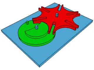
In this External Geneve Drive, the driven wheel is connected with rotating drive wheel externally. This is the most popular Geneva Drive and used in many mechanical products like watch and film projector. It can withstand higher mechanical stresses.
Internal Geneva Mechanism :
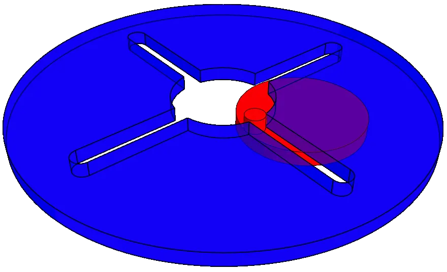
In internal Geneva Drive, the driven wheel is connected with the rotating drive wheel internally. Both the driver and the driven wheel rotate in the same direction. Its disadvantage is that it cannot be built smaller and cannot withstand higher mechanical stresses like external Geneva drive.
Spherical Geneva Mechanism :
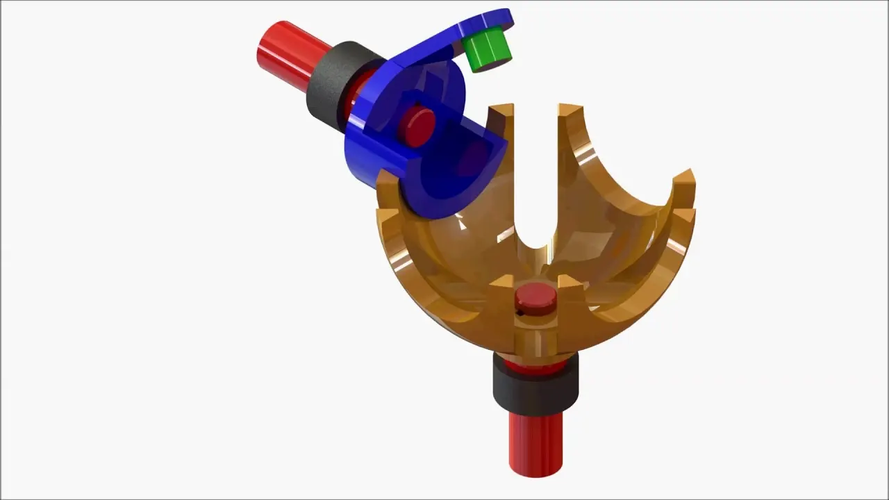
In Spherical Geneva Drive, the driven wheel is in spherical shape and is connected to rotating drive wheel externally. In this driving and the driven wheel are on perpendicular shafts i.e input and output shafts are perpendicular to each other.
Procedure :
Modelling and Assembly :
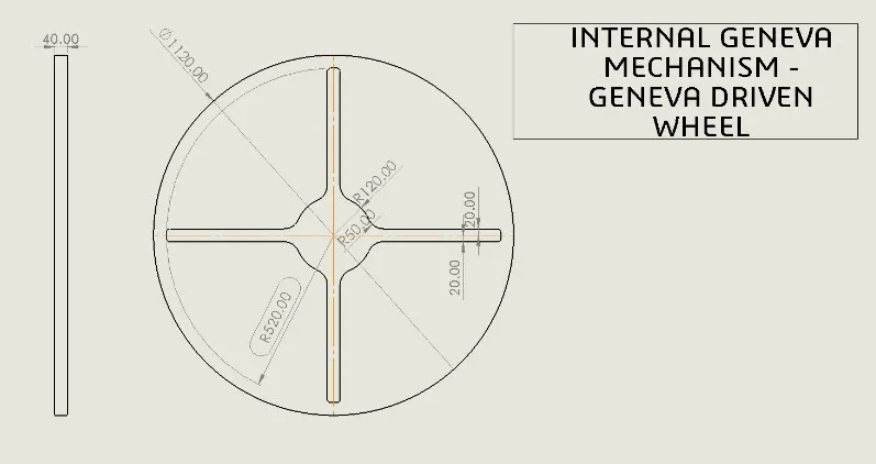
Given 2D Drawing file :
Driven Wheel :
Driver Wheel :
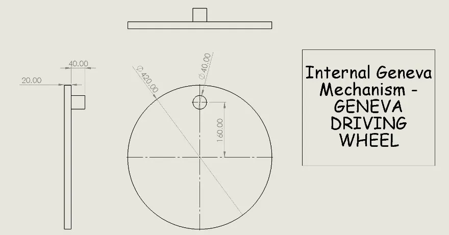
1) Create a 2D sketch of the Driven wheel as per the given dimensions and then converted into the 3D part and save it as part file.
2) Next Create a 2D sketch of the Drive wheel of internal Geneva as per the given dimensions and then convert it into 3D part model and save it as part file.
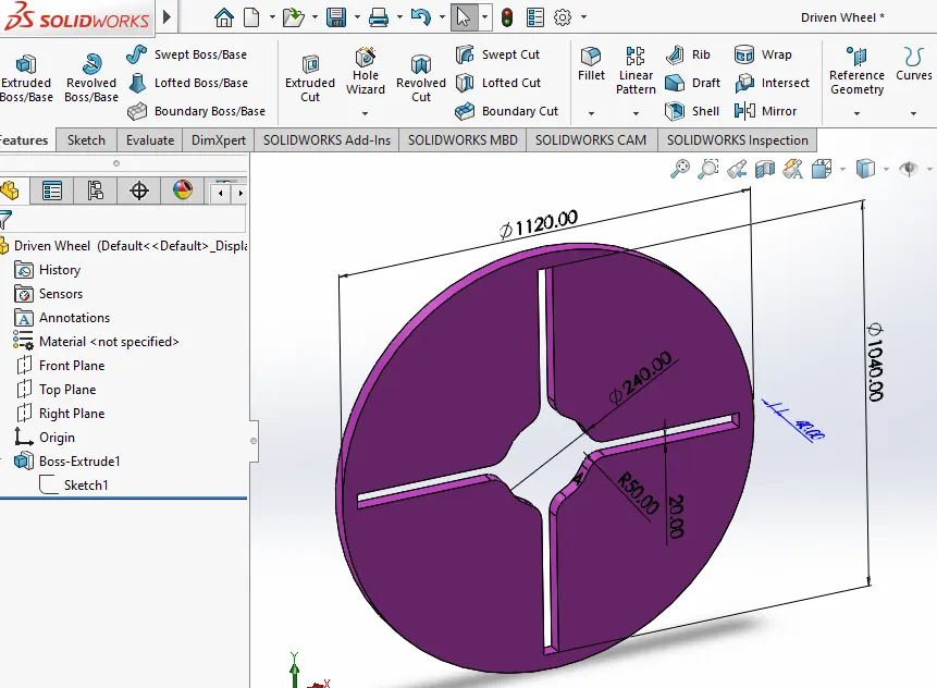
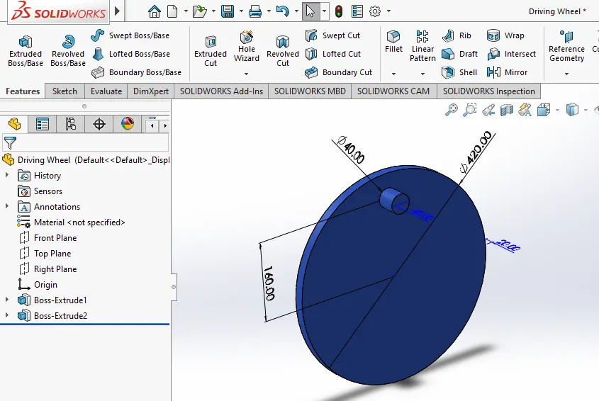
3) Open a new file as assembly part file and import both the parts of internal geneva i.e the Driver wheel and driven wheel.
4) Using various mates assemble the internal geneva's Driving wheel with the Driven wheel as needed and also at a certain distance from center of each wheels.
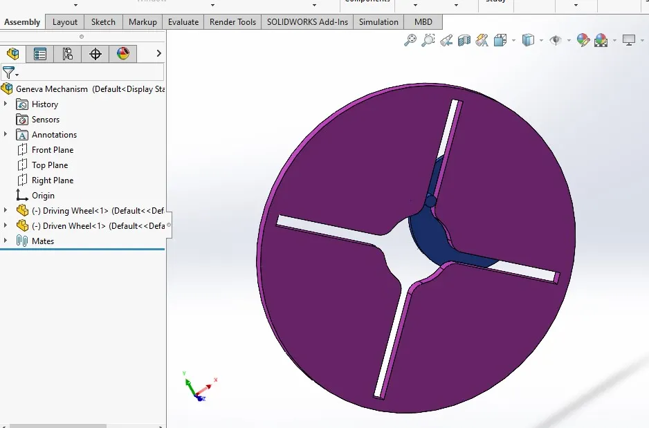
5) Save the assembled file separately and open it in a new window for motion analysis.
6) Start with the motion study setup, select the motion analysis and then set the various parameter for it.
7) Add motor to the driver wheel at its center axis with certain RPM initially at 10rpm as per the given conditions.
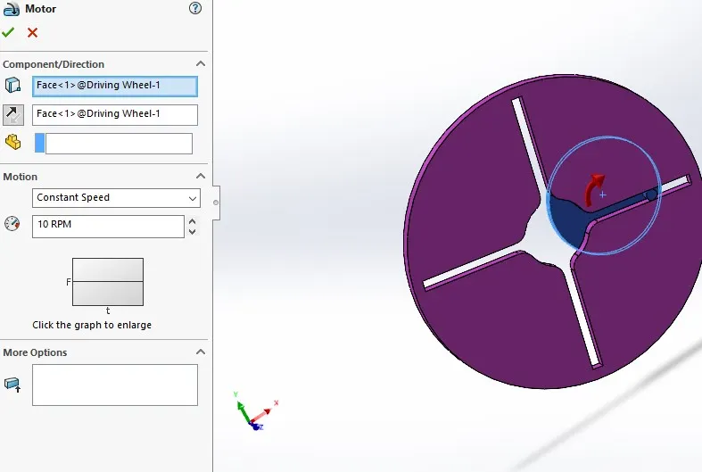
8) Add solid contact face for the mechanism that is driver and driven wheel with a material respectively.
9) Calculate the contact force between driver and driven wheel by selecting its face and showing the plots for results.
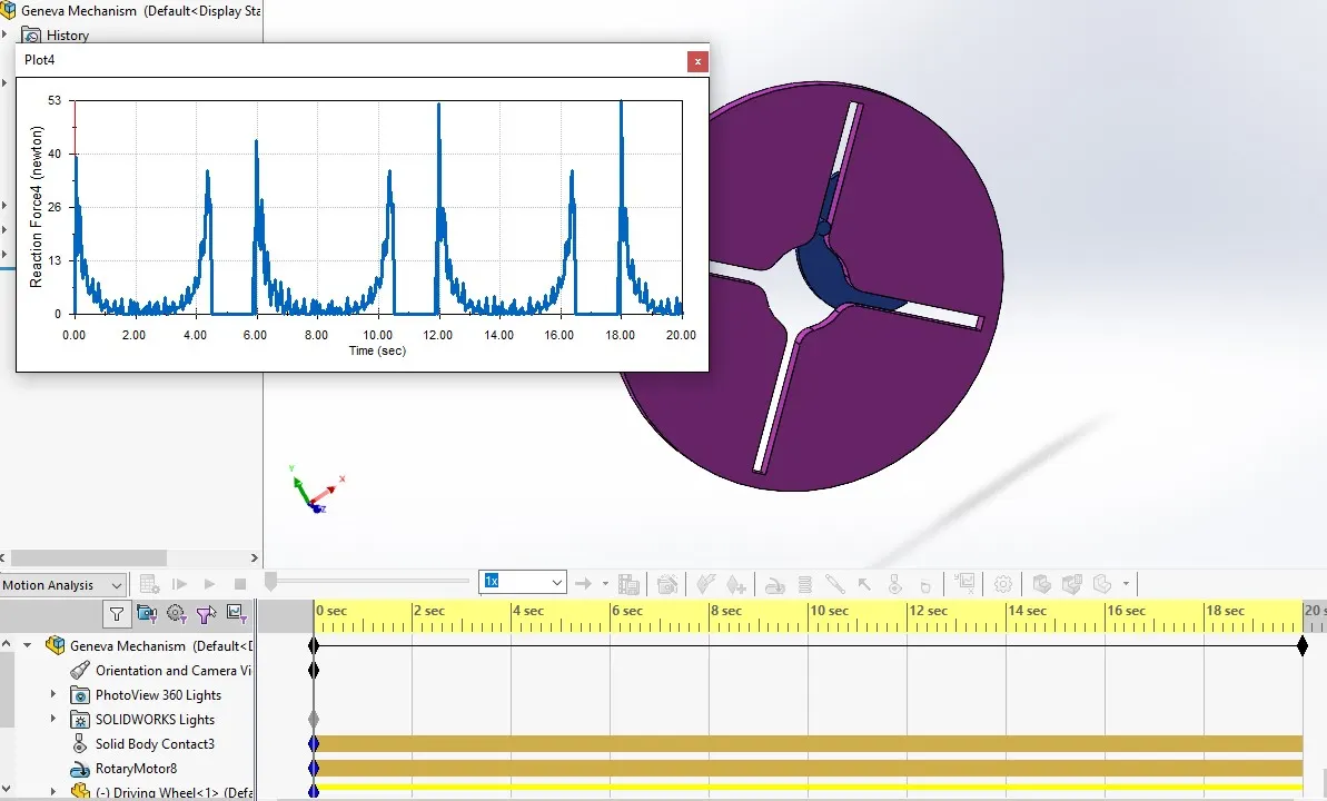
10) Also, select the angular displacement option for driven wheel and angular velocity for driver wheel respectively.
11) From the given conditions set the frame as 60fps for 10rpm motor initially and then 120fps for 20rpm motor with and without precision contact.
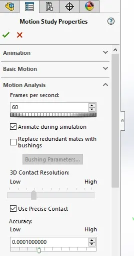
12) Click the calculate option to start the study to get all the plots and results as we need and export those result of plots as the Excel files and compare the results.
Results :
1) Initial condition :
For the starting after assemble the parts add the motor at 10rpm and contact relation. Take the plots fot contact force while running the mechanism and results as shown in next image.
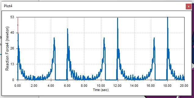
From the above plots we can see that contact force changed with respect to time. And we can see there is no smoth flow in the graph. For that we need to change some starting setting in our motion study.
2) With precise contact : (60FPS and 10rpm)
In this study we change some setting for get the accurate and study flow in the plot. So, here motion study is done in the 60FPS and with Precise Contact on. From that setting we can get more accurate results as shown in image.
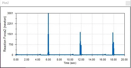
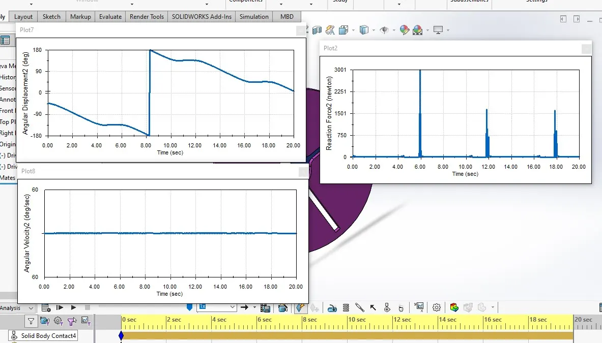
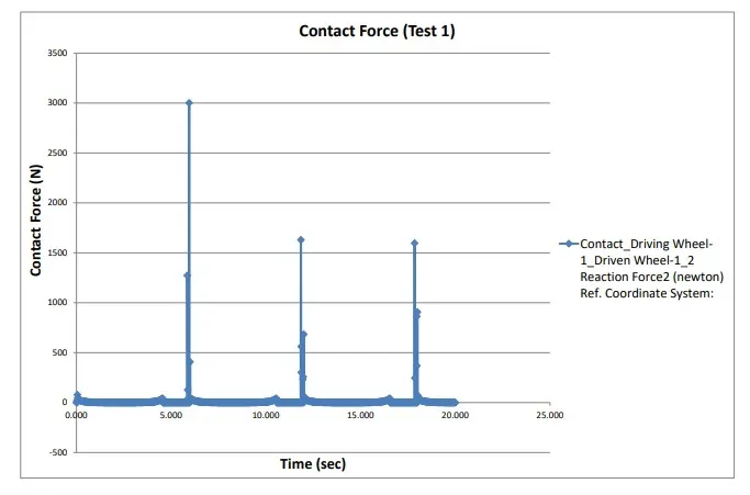
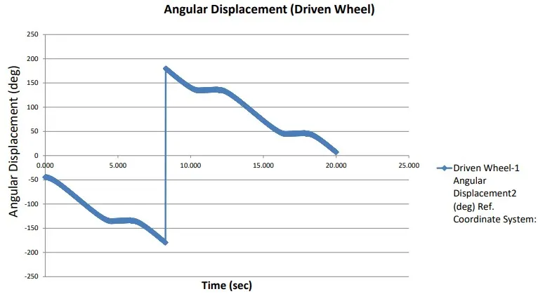
From this plot we can get the study flow in the contact force and it go upto 3000N and it contact the part three times in the 20sec. Similarly we need to find the angular displacement of the driven wheel and angular velocity of the driver wheel. And next step is to export the data to excel sheet as follows.
Export files :
Contact Force :
Angular Displacement of Driven wheel :
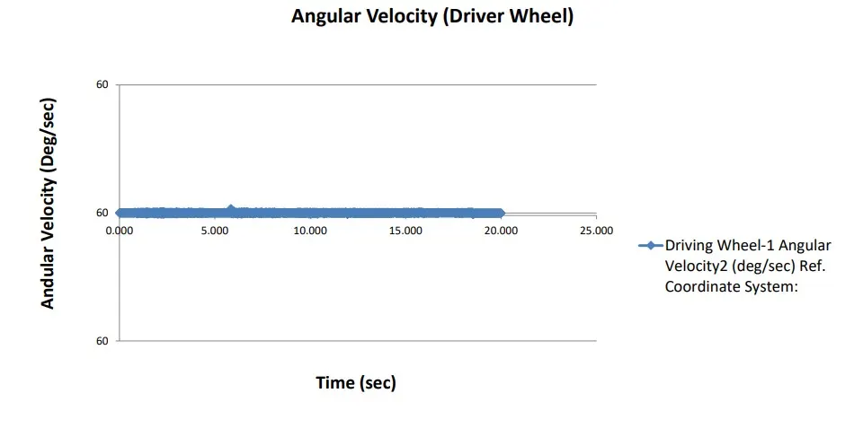
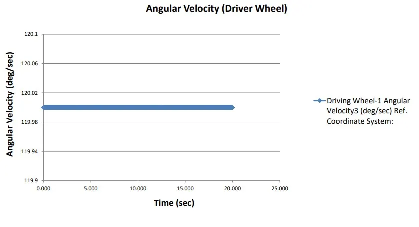
Angular velocity of Driver Wheel :
3) With precise contact : (120FPS and 20rpm)
In this study we change some setting for get the accurate and study flow in the plot. In this study we need to change the motor rpm as 20rpm to get more contact force reults. So, here motion study is done in the 120FPS and with Precise Contact on. From that setting we can get more accurate results as shown in image.
b 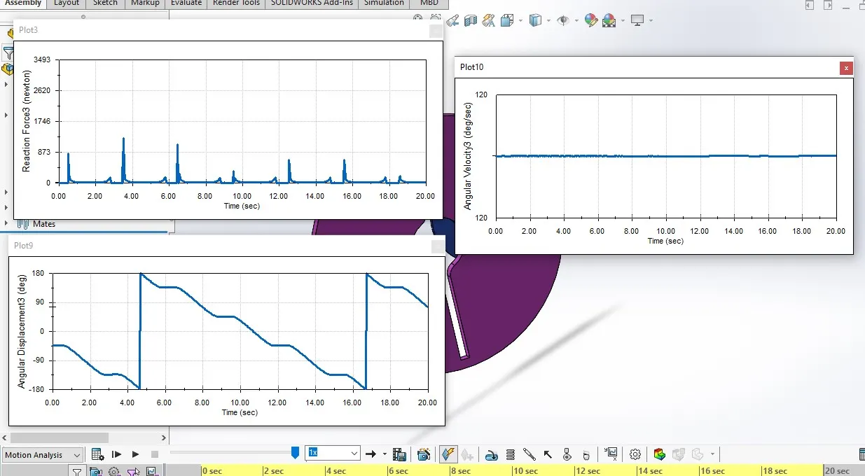
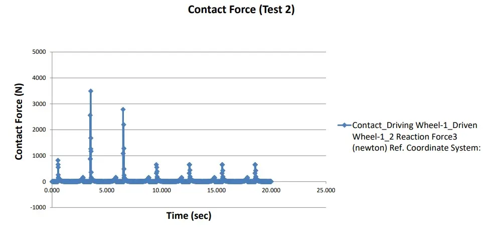
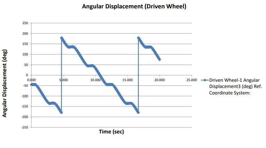
From this plot we can get the study flow in the contact force and it go upto 1500N from the beginning as the next contact it down and make smooth contacts. It contact the part six times in the 20sec. Similarly in the angular displacement of the driven wheel it make more smooth curve flow when compared to the previos plots. Angular velocity of the driver wheel is not change much in the hole time as we can see in the plot.
Export files :
Contact Force :
Angular Displacement of Driven wheel :
Angular velocity of Driver Wheel :
Conclusion :
From the above results and plots first without precison we get lot of variation in the graph flow. in the next precison contact and 60fps we get more reliable results. And next step we increse the speed of the motor as 120rpm in this time for more accurare results and the contact force also get very smooth curve.
So, in this analysis the driven wheel is rotates at some intervel regularly. we can understand for the smooth flow the motor rpm and the distance between the wheels is the critical parameter for the smooth transition.
From the plots we can understand the sync error even it is very small also, and which is help to make perfect sync and force details also as per time.