Planetary Gear
Planetary Gear Assembly
Aim :
To Create Planetary gears assembly using part modeling and import gears from design library. After assembling gears analysis the input and output gear speeds by using the motion study in solidworks software.
Objective :
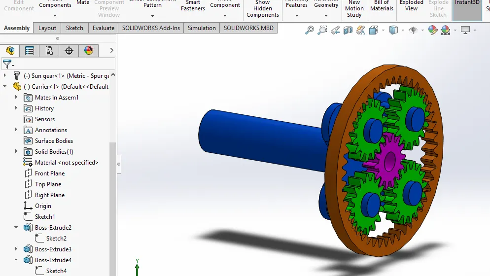
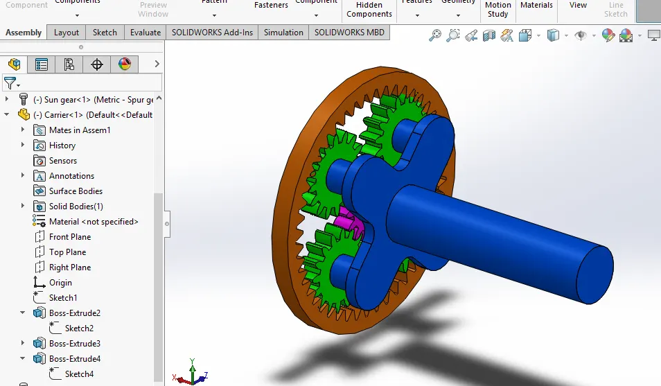
1) To import/design and assemble planetary gears, ring gear, sun gear and carrier by giving required constraints.(using ANSI metric unit)
2) To run the simulation and study the motion analysis of the whole assembly.
3) To plot angular velocity graph from the motion analysis (for different cases) and conclude results.
Theory :
Planetary gears normally consist of three parts. A single sun gear at the centre , an internal gear around the outside, And some number of planets that go inbetween. Generally the planets are the same size, at a common center distance from the centre of the planetary gear, and held by a planetary carrier.

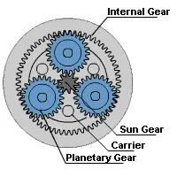
In your basic setup, your ring gear will have teeth equal to the number of the teeth in the sun gear, plus two planets (though there may be advantages to modifying this slightly), simply because a line straight across the centre from one end of the ring gear to the other will span the sun gear at the centre, and room for a planet on either end. The planets will typically be spaced at regular intervals around the sun. to accoumplish this, the total number of teeth in the ring gear and sun gear combined divided by the number of planets has to equal a whole number. Of course,the planets have to be spaced for enough from each other that they do not interfere.
This arrangement affords several advantages over other possible arrangements, including compactness, the possibility for the sun, ring gear, and planetary carrier to use a common cenetral shaft, high 'torque density' due to the load being shared by multiple planets, and tangential forces between the gears being cancelled out at the center of the gears due to equal and opposite forces distributed among the meshes between the planets and other gears.
Given informations :
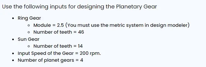
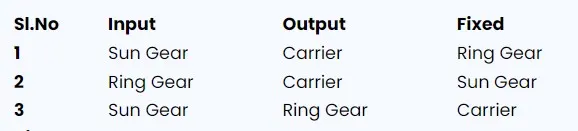
Calculations :
So, here we need to calculate PCD of all gears and number of teech in planetary gear.
Formulas :
Module (M) = PCD / No of teeth
PCD (Planetary gear) = [PCD (Ring) - PCD (Sun)] / 2
For Ring Gear,
M = 2.5 (given)
M = PCD / 46
PCD (Ring) = 46 * 2.5
PCD (Ring) = 115 mm
For Sun Gear,
M = 2.5 (given)
M = PCD / 14
PCD (Sun) = 14 * 2.5
PCD (Sun) = 35 mm
For Planetary Gear,
PCD (Planetary gear) = [PCD (Ring) - PCD (Sun)] / 2
PCD = (115-35)/2
PCD = 80/2
PCD(Planetary) = 40mm
M = 2.5 (given)
2.5 = 40 / N
N = 40 / 2.5
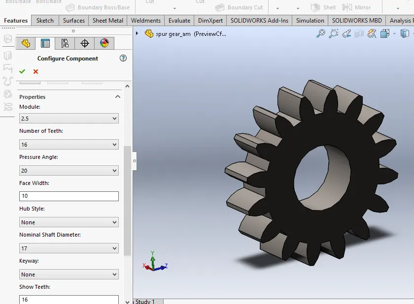
No of teeth (Planetary) = 16
Carrier Design :
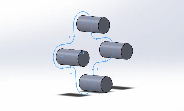
For carrier from the given information there are 4 gear arrangements and we need to find the PDC for carrier by using the solidworks sketch environment as shown in figure.
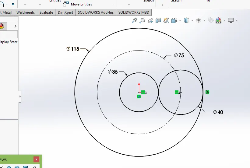
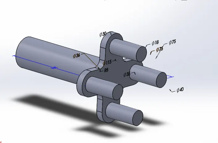
PCD of Carrier = 75 mm
Now ,we ready to create the carrier part in part workbench using solidworks software as shown in following images.
Import Gears from Design Library :
- For creating gear from toolbox - go to design library - Toolbox - ANSI metrc - power transmission - gears
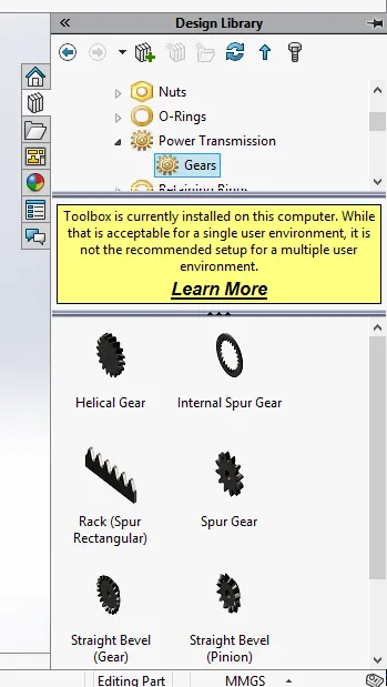
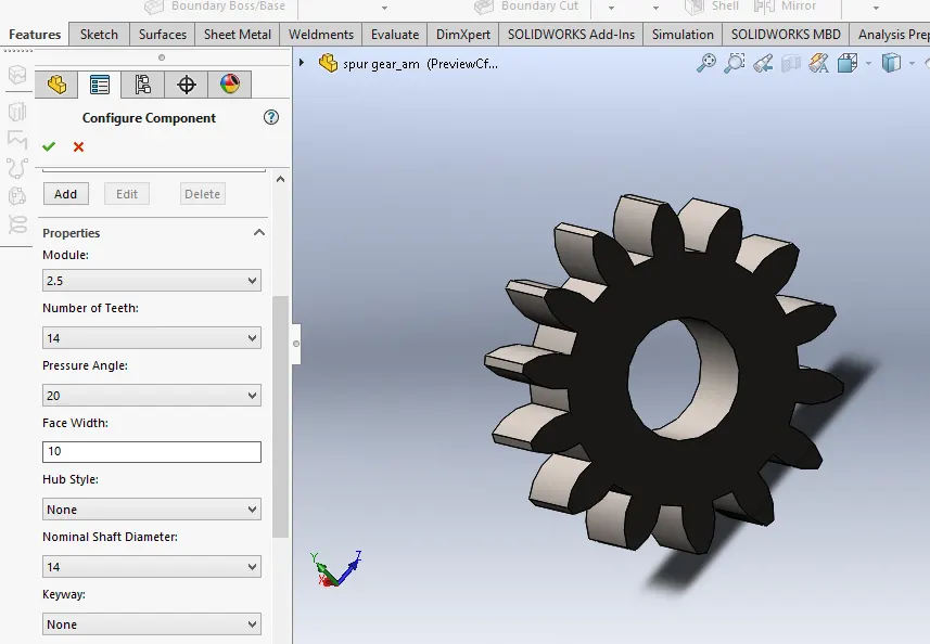
- For sun and planetary gears choose spur gear
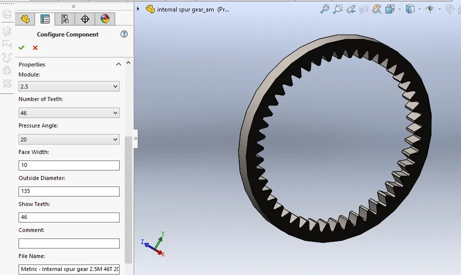
- For ring gear need to choose internal spur gear
- Pressure angle = 20
- Face width = 10mm
Ring Gear :
Sun Gear :
Planetary gear :
Final Assembly :
Motion Analysis :
In the motion study make contacts between the followings.
- Carrier and Planet gears
- Sun gear and the planet gears
- Ring gear and the planet gear
The material for each contact is steel(Dry)
The input speed to the motor in each case is 200 rpm.
And, Those 3 cases are,
And for the output we need to create the plot in motion study to find angular velocity as shown in image,
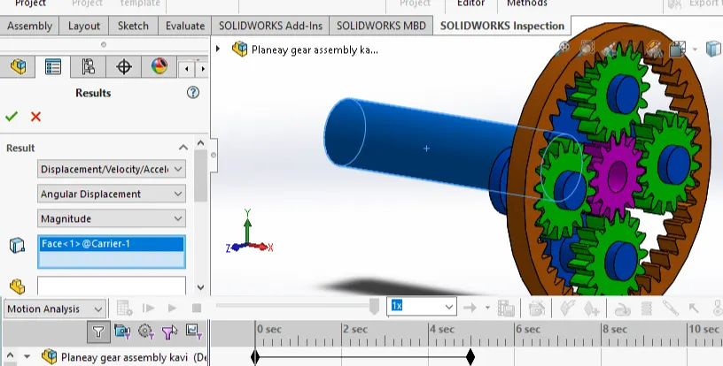
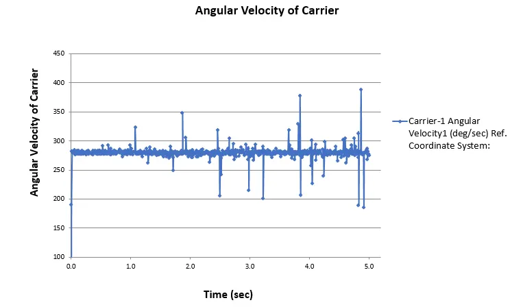
Case 1:
- When the Ring gear is fixed.
- Input is given to sun gear.
- Output is taken through Carrier (Angular velocity).
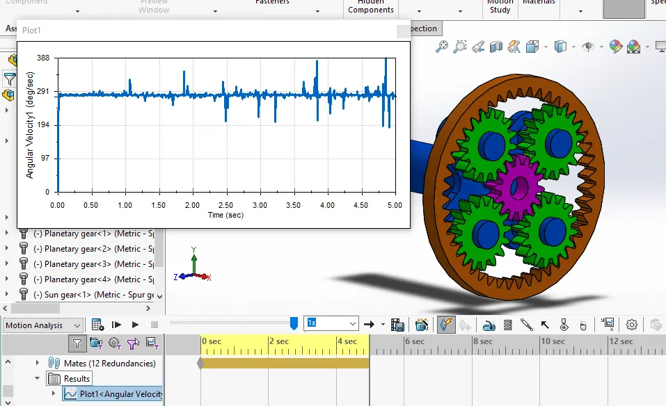
This plot is for the Carrier Angular velocity with respect to the time has plotted. The input speed is constant 200rpm. By this plot we can say the output speed is incresed as the range of 280rpm to 290rpm.
Case 2:
- When the Sun gear is fixed.
- Input is given to Ring gear.
- Output is taken through Carrier (Angular velocity).
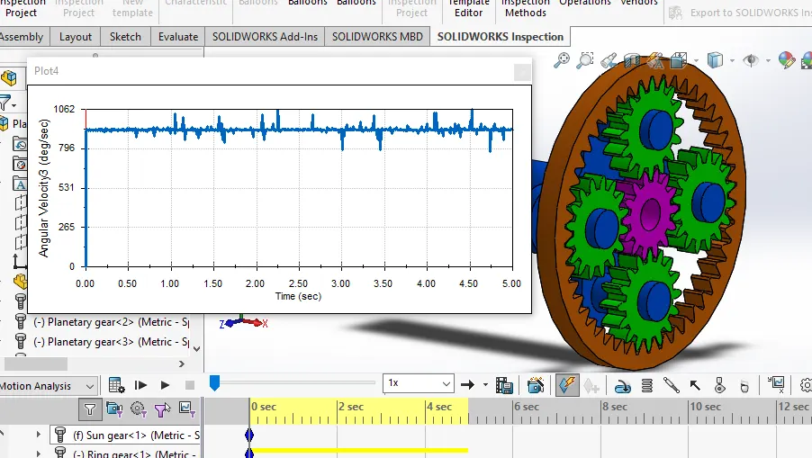
This plot is for the Carrier Angular velocity with respect to the time has plotted. The input speed is constant 200rpm. By this plot we can say the output speed is incresed as the range of 900rpm to 920rpm.
Case 3:
- When the carrier is fixed.
- Input is given to sun gear.
- Output is taken through Ring gear (Angular velocity).
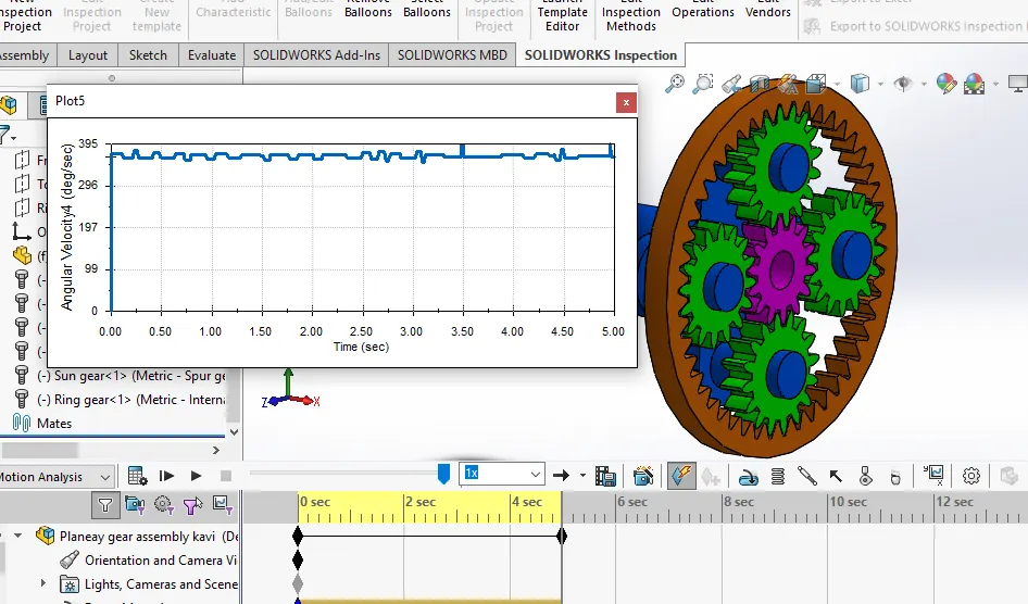
This plot is for the Ring Angular velocity with respect to the time has plotted. The input speed is constant 200rpm. By this plot we can say the output speed is incresed as the range of 360rpm to 370rpm.
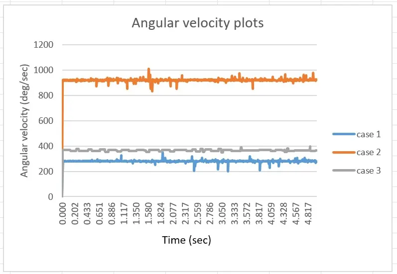
Finally this plots are exports to excel sheet for the comparision among them.
And the plot this all three case into single plot using the excel sheel tool as shown in figure.
Observation :
From the study we can understand that when the fixed gear and input is changed the output speed is varing for these different cases. From the case 1 the output speed is almost 290 rpm. In the next case 2 is 910rpm and for case 3 is 370rpm.
So, we can get the required speed by change the fixed and input gear in the planetary gear setup.
Conclusion :
From this study in the planetary gear arrangement by give the same input speed but we can get the three various output speed. This is why this planetary gear setup is used in the automatic gear change cars. By modify the no of teeth of a gear we can get required speed ration in the cars and other applications.
Files attached :
1) part and Assemble file
2) Animation Video