Wiring harness design in CATIA V5 - 3D modeling Week 2 Challenge
Define the 3D model as Electrical Connector
Aim :
To download the connectors and clips CAD file and define that 3D model as the electrical connector by using the Electrical part design workbench in the CATIA V5 software.
Objective :
- Download the below listed 3D cad model of the connector and clip from the te.com.
- Define that 3D model as the electrical connector by using the electrical part design workbench.
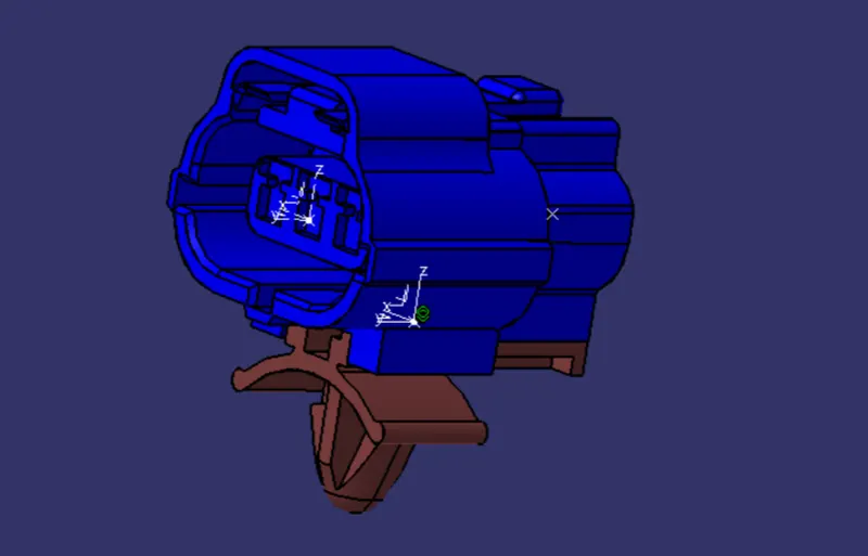
- Assemble the connector and clip in the Electrical Assembly Design.
3D CAD models :
- Deutsch DT06-08SA [Male connector]
- Tyco 174357-2 [Male connector]
- Tyco 85229-1 [clip]
Theory :
For make the 3D model as electrical connector we need some geometrical parameter to represent in the electrical part design so we create some point and the axis system in the part workbench itself. After the we follow some other steps as given in the following importent steps.
Connector Definition :
- Create or download connector 3D model.
- Create required Geometrical parameter in the part design workbench.
- Define part as connector in the electrical design workbench.
- Define Bundle connection point by using ponit and axis.
- Define connector connection point by using point and axis.
- Define cavity connection point by using point and axis.
Deutsh DT06-08SA :
Create required Geometrical parameter in the part design workbench as shown in figure.
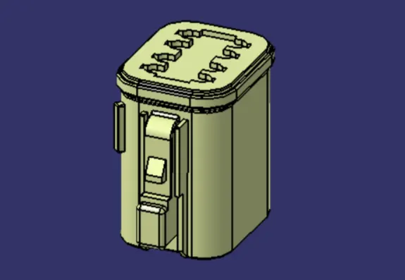
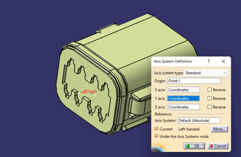
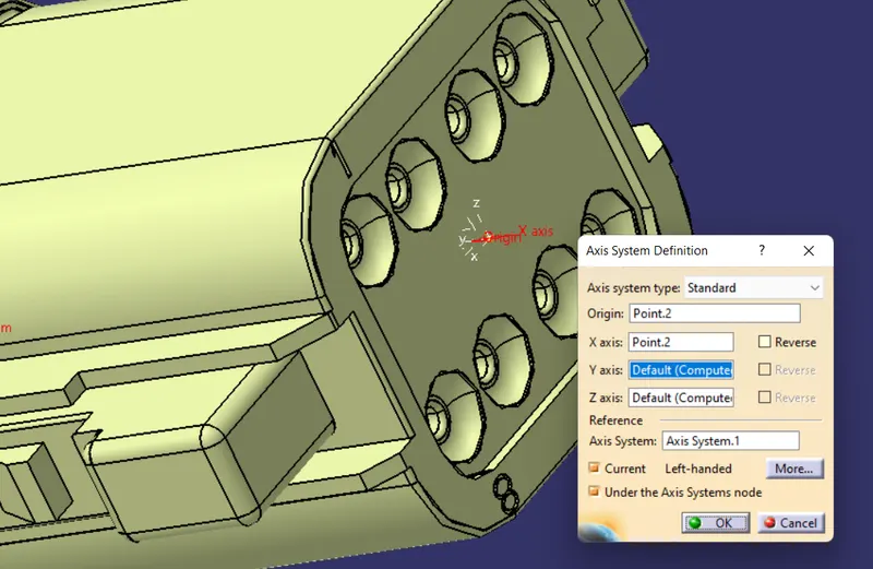
Define part as connector in the electrical design workbench as shown in figure.

Define Bundle connection point by using ponit and axis as shown in figure.
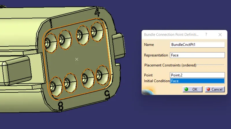
Define connector connection point by using point and axis as shown in figure.
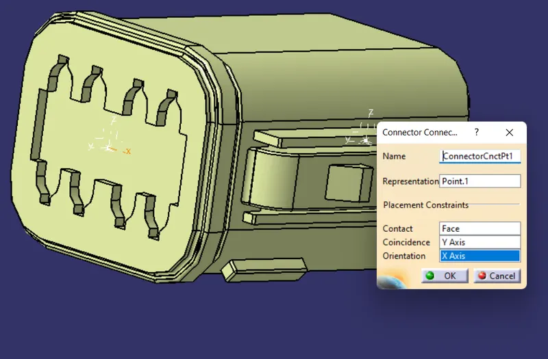
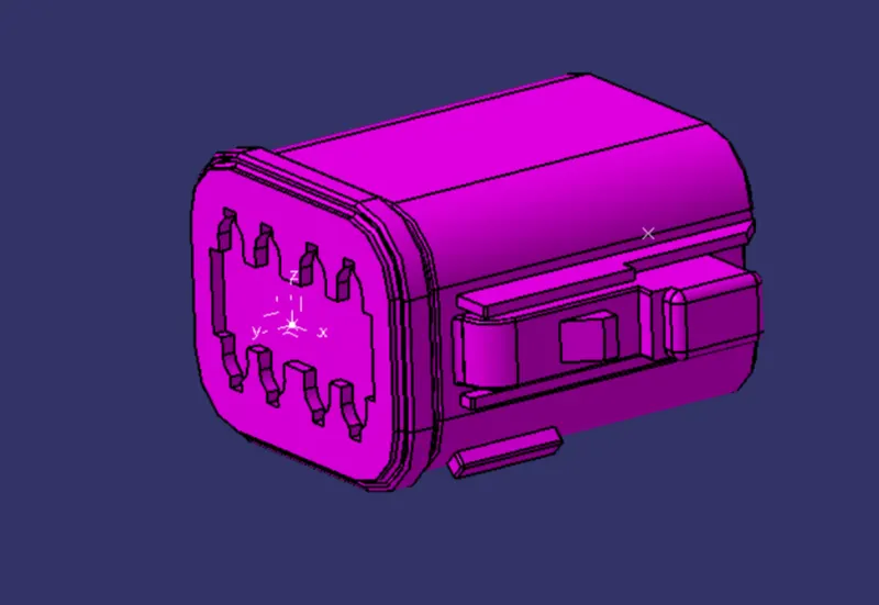
Tyco 174357-2 :
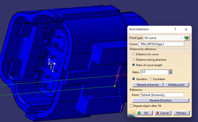
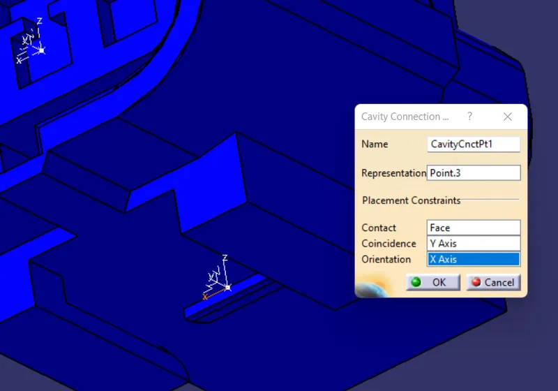
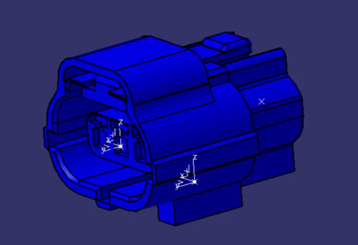
Similarly we define this 3D part as the electrical connector in the electrical design workbench as shown in figure.
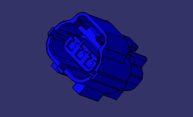
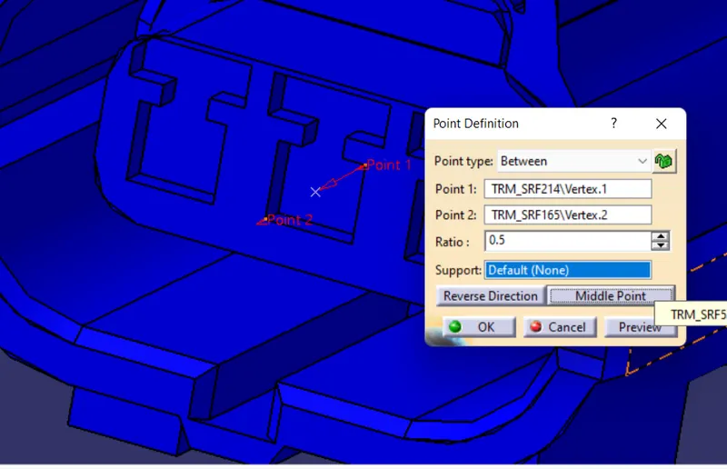
Tyco 85229-1 [clip] :
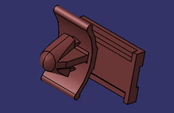
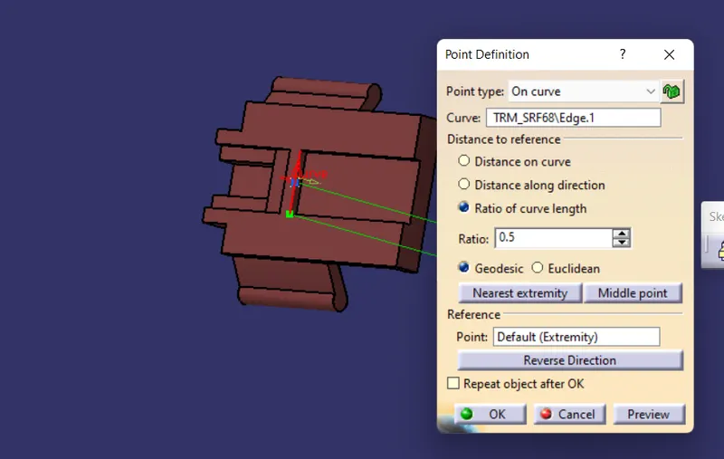
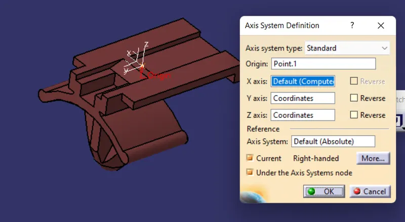
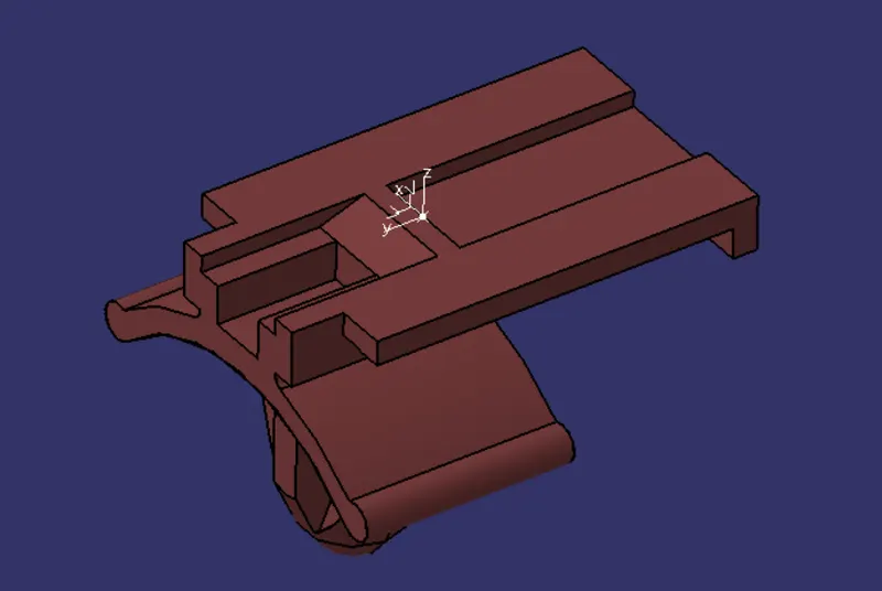
Similarly we define this 3D part as the electrical connector in the electrical design workbench as shown in figure.
Electrical Assembly design :
Conclusion :
Hence the connectors and clips CAD file and define that 3D model as the electrical connector is defined by using the Electrical part design workbench is successfully done in the CATIA V5 software.