Week -2
Aim :
1) To make simulink model for a doorbell using solenoid block.
2) To use thermistor to sense temperature of a heater and turn on/off the fan.
1) Door Bell :
Theory - Solenoid :
Basic definition, A solenoid is a device comparised of a coil of wire, the housing and moveable plunger. When an electrical current is introduced, a megnetic field forms around the coil which draws the plunger in, more simply, a solenoid converts Electrical energy into Mechanical work.
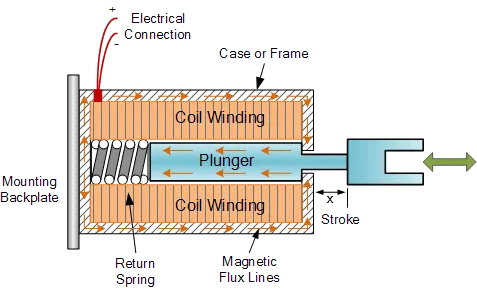
Build components inside a Solenoid :
- The coil is made of many turns of tightly wound copper wire. When an electrical current flows through this wire, a strong megnetic field/flux is created.
- The housing, usually made of iron or steel, surrounds the coil concentrating the magnetic field generated by the coil.
- The plunger is attracted to the stop through the concentration of the magnetic field providing the mechanical force to do work.
A solenoid is a type of eletromagnet, the purpose of which is to generate a controlled magnetic field through a coil wound into a tightly packed helix. The coil can be arranged to produce a uniform magnetic field in a volume of space when an electric current is passed through it. The term solenoid was coined in 1823 by Andre Marie Ampere to designate a helical coil.
In engineering, the term may also refer to a variety of transducer devices that convert energy into linear motion. The term is also often used to refer to a solenoid valve, an intergrated devices that containing an eletromechanical solenoid which actuates either a pnematic or hydraulic valve, or a solenoid switch, which is a specific type of relay that internally uses an electromechanical solenoid to operate an electrical switch.
There are various applications of a solenoid, one of those is an actuated door lock mechanism.
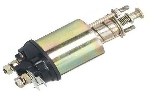
fig: Soleniod Switch
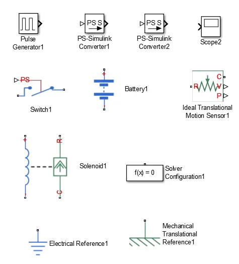
Blocks used for create Door Bell model :
Simulink model - Door Bell :
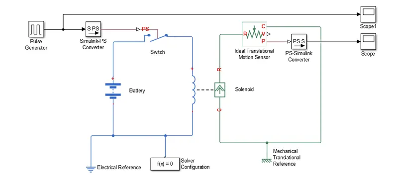
Explanation :
1) As per the given condition switch is closed for 2 seconds and then released. The pulse generator is used to create square wave pulses at regular intervals. The block waveform parameters, amplitude, pulse width, period and phase delay. For our signals we need to give the following as the input which is shown in figure
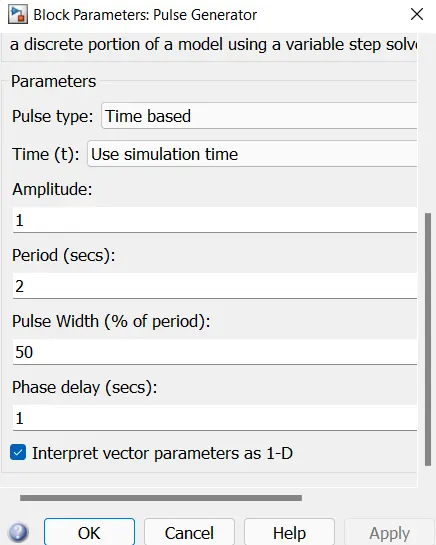
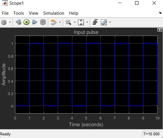
by give this pulse width as 50 % we get the even pulse for the period of 2 sec upto 10 sec.
2) Then simulink-ps converter is used to convert the simulink signal to physical signal. This is connected to a switch controlled by external physical signal with all of its setting left in defult, the switch is closed when it receives the signal, otherwise it is open
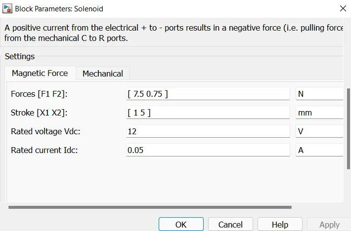
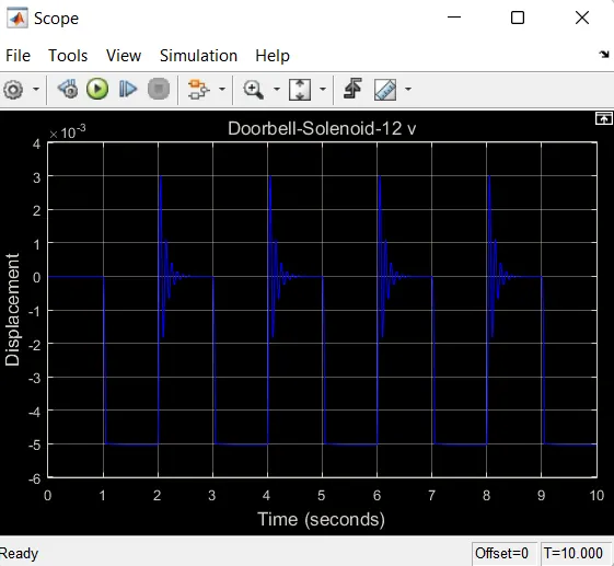
3) This is connected to a battary and then the whole circuit is grounded by an electrical reference. Then the battary and switch were connected to the positive and negative terminals of the left side of the solenoid block, then the case terminal was connected to a mechanical translational reference, all the setting of the solenoid were left in default. in the solenoid block the default voltage is 50v and we get the output as 1 sec to 1 sec ring. so, i change the voltage in the solenoid as 12 volt as shown in figure
4) Then in order to detect the movement of the solenoid, an ideal motion translational sensor was used, its reference is connected to the reference of the solenoid and its case was connected to the mechanical translational reference, all of its settings were left in default.
5) Then a signal is taken from the plot which measure the displacement and connected to the solver configuration block which is required as each and every simscape circuit needs to be attached with the solver configuration block as it specifies the solver parameters that the model needs beginning the simulation.
6) Then the signal is converted to simulink signal via ps-simulink converter, and then it is connected to a scope to display it.
Output :
scope : input pluse
output : scope-solenoid at 50v
In the scope plots we can change or modify for our requirements. by clicking the setting option. we can give title to plot and axis name, color of the curve, bg color axis color, line width etc..
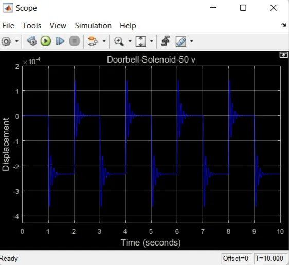
output : scope-solenoid at 50v
2) Thermistor - ON/OFF the fan
Theory :
Thermistor :
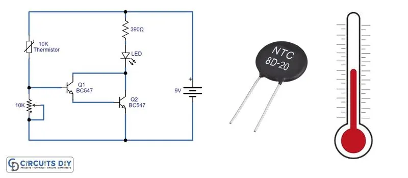
A thermistor is a resistance thermometer, or a resistor whose resistance is dependent on temperature. the term is a combination of 'thermal' and 'resistor'. Thermally sensitive resistor which exhibits a precise and predictable change in resistance proportional to small changes in the surrounding temperature.
The word "Thermistor" is derived from "Thermally sensitive resistor", whose resistance change with the change in temperature. Thermistor are very sensitive to the change in temperature therefore they are perfact to detect the changes in the tamperature while recording the temperature or operate electrical applications such as AC, fan, oven, automotive and areospace applications. There are a vast range of applications where thermistors can be used, and different size and shapes of thermistors are available in the market depending upon the applications.
There are mainly two types of thermistors, NTC and PTC.
NTC : Negative Temperature Coefficient thermistor.
PTC : Positive Temperature Coefficient thermistor.
With an NTC thermistor, when the temperature increases, resistance decreases. Conversely, when temperature decreases, resistance increases. This type of thermistor is used the most.
A PTC thermistor works a little differently. When temperature increases, the resistance increases, and when temperature decreases, resistance decreases. This type of thermistor is generally used as a fuse.
In this study NTC type thermistor is used.
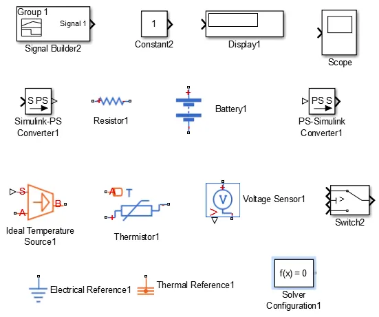
Blocks used for Thermistor-ON/OFF a fan model :
Simulink model - Thermistor-ON/OFF a fan model :
Explanation :
1) In the given conditions,
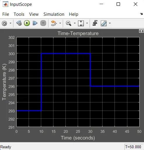
Temperature source - 20 degree C from 0 to 10 sec, 27 degree C from 10 to 30 seconds and 23 degree C from 30 to 50 seconds.
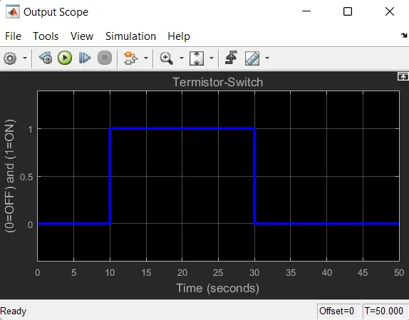
Fan conditions - ON if temperature above 25 degree C, OFF otherwise.
so, for our understanding,
0-10 sec => 20 degree C =>293 K => fan OFF
10-30 sec => 27 degree C =>300 K => fan ON
30-50 sec => 23 degree C =>296 K => fan OFF
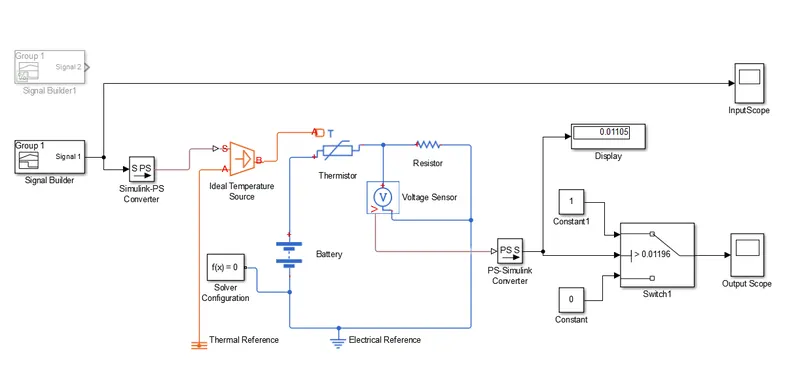
Signal builder is connected instead of the constant where a signal of time values of [0 10,10 30,30 50] and a temperature values of [293,300,296] were used to generate a signal.
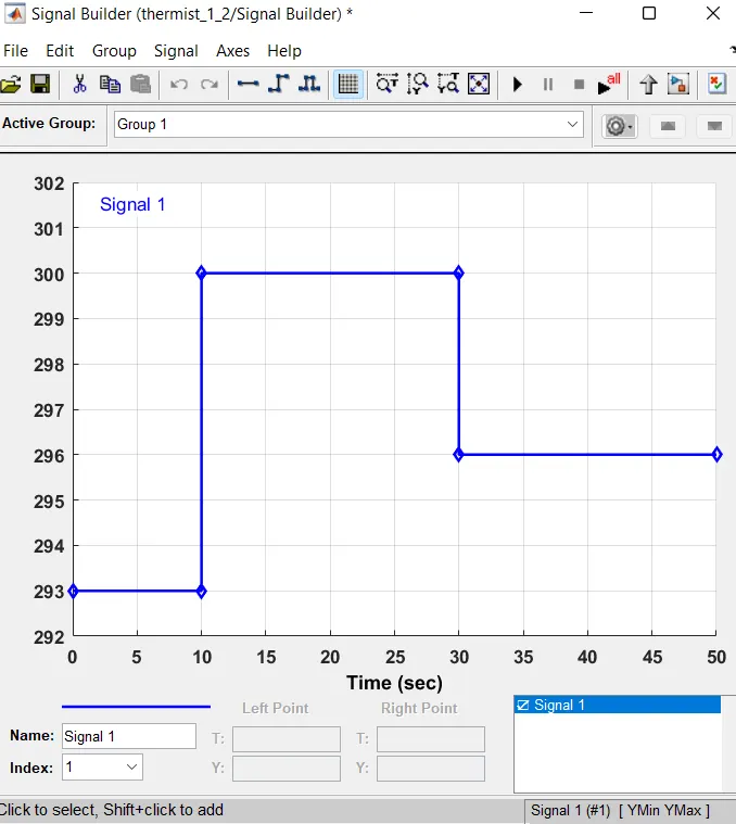
2) The simulink ps converter was configured differently to take the first derivatives in order to provide enough inputs and to provide the derivatives required. and this ps converter is connected to ideal temperature source. As we discussed above the themistor is conneted with temperature source and to voltage sensor to find out the voltage accross the resistor and thermistor.
3) And then this output of voltage difference is connected to input of switch before that we need to conver the signal by using the ps-simulink converter as shown in figure. Then this output is connected to scope which shows that tha fan ON orOFF condition.
4) In that circuit we use two references are namely thermal reference and another one is electrical reference. This switch has two constant are 0 and 1. so the out put of switch is 0 or 1. And 0 for OFF condition and 1 for ON. in between the switch and voltage output there is one display is connected for show the out put of voltage difference.
5) In the given codition for above 25 deree (298 K) only the fan need to ON codition. so, we generate the signal for 298 K and pass it through thermister and get the voltage difference value. For that i generate one signal for 298 K and 10 sec as shown in figure.
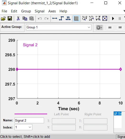
And then i get the result from the display which is conneted to the voltage sensor and value for 298 K is 0.01196 as shown in figure.
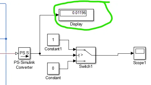
so we the value for 25 degree C. we need to feed it to the switch for when to ON/OFF.
6)In the switch it have two constant as 0 and 1 and one input from the voltage sensor. In that switch parameter box we need to give the threshold as we known from the display value of 0.01196. so the value above only this switch is ON codition othervise in OFF condition.
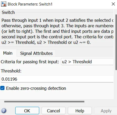
7) Finally plot graphs from the scope and give proper title and axis name. And the ouput graph shows that 0 to 10 sec as OFF condition and 10 to 30 sec as ON conditon and 30 to 50 sec as OFF condition.
Outputs :
Input Scope :
Output Scope :
Conclusion :
It can be concluded that both the studies were a success where outputs observed were,
1. When a doorbell rang, a deflection was observed in the scope plot.
2. The temperature differences noticed by the thermistor and switch ON/OFF the fan was observed and plot by the scope.