Project 2
Car Back Door wiring Harness
Aim :
To route the wiring harness on the car Back door assembly by concidering the all packaging rules, industry best practies and apply the production covering to the required wiring. And finaly prepare the flatten Drawing for wiring.
Objective :
- To create required geometrical parameters and Define all connectors and clips as Electrically defined by using the Electrical design workbench.
- To create the production include engine and all connectors in that.
- To route the wiring harness as per the all packaging rules by using the Electrical Harness assembly workbench.
- To create the flatten Harness and create the Drawing file from it.
Introduction :
The automotive wiring harness is referred to as the central nervous system in the vehicle. It mainly consists of an electrical harness and the mechanical harness in the design. The current project is focused on the mechanical harness in the design. The current project is focused on the mechanical wiring harness and its rules and procedure to be followed while routing in the virtual condition. CATIA V5 electrical workbench is used as the CAD tool for routing the wires in the engine and tailgate components.
Wiring harness terms :
Wiring harness is the assembly of different system, sub-system in the vehicle. It won't have any function. It depends on its system and sub-system. It used to pass the signals between components.
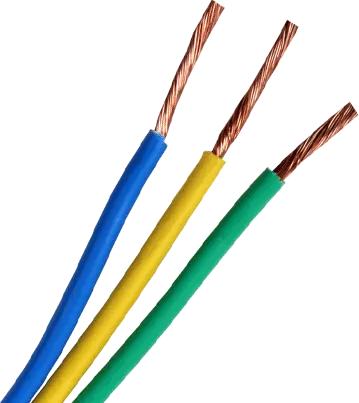
1.Wires : Wiring harness consists of various wires bundled together, with each individual wire responsible for carring electric signals and energy used in starting the engine, lights, meters, navigation system, power windows and Doors and other devices in the vehicle. Wires are Cu conductors insulated with PVC insulation.
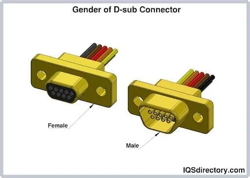
2.Connector : An electrical connector, is an electro-mechanical devices used to join Electrical termination and create an electric circuit. Electrical connectors consist of housing, Terminal, wedge locks, Seals, Cavity mounting Cam etc.., Connectors are plastic moulded housing with locking and retention features.
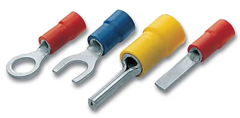
3.Terminals : Terminals are defined as A device designed to terminate a connector that is to be affixed to a post, stud, chassis,another tongue, etc, to establish an electrical connection. Terminal are metal (brass) conductor with plating (tin,silver,gold) constructed in specific shape to ensure the joins from the environmental condition and with minimum electrical resistance.
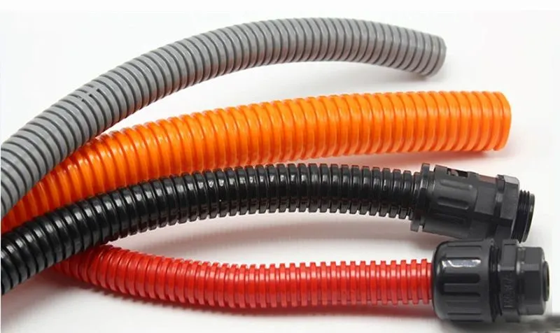
4.Protection device : Corrugated flexible tubes also known as cot tubes/convoluted conduits have a wide range of application in automotive industries. Corrugated tubes are made from plastic material and they are flexible. Production covering are flexible, temperature, wear and tear resistant moulded plastic/polymer parts.
Harness Packaging:
Harness packaging involves the decisions of harness mountings (Clip&clamp) and Routing management (Use pf Brackets, Channels, Guiding Devices)
It also deals with
- Thermal management
- Manufacturability
- Clearance managements
- Aesthetic requirements etc...
Packaging rules and Assumptions :
- Provide enough clearence to the wiring harness with respect to the surrounding.
- Aviod harness routing and clipping in blind zone.
- Provide additional slack to the harness according to the surrounding. 5-10% of slack.
- Branch length should maintain with 50mm.
- Minimum distance between clip and nearest branching point should be 25mm.
- Routing through small structural holes and openings shall be avoided, to minimize chaffing and handling of the wiring harness during installation.
- Avoid routing over the bolts, near to the joints.
- Keep the harness away from the panel mounting bolts and screws.
- Harness should be kept away from Engine Lifting hooks.
Procedure :
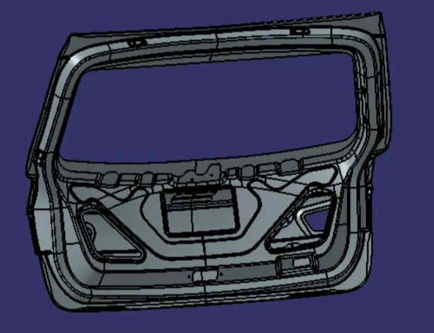
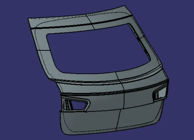
In this project we going to routing the wiring harness for the car Bach door assembly part by using the CATIA V5 software. Which is provide various Electrical platform such as Electrical Design, Electrical harness assembly, Electrical Harness Installation, Electrical Flattening Harness. By using this workbench route the wiring harness for the car back door assembly. So, the given back door assembly part is the step file as shown in figure.
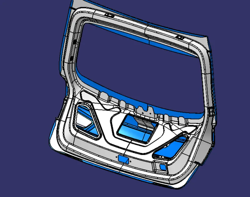
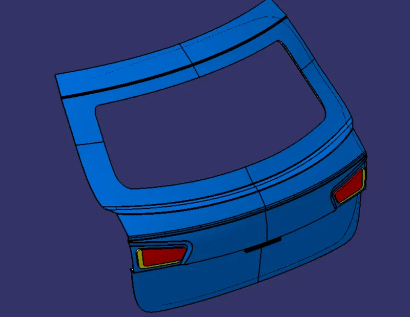
The next step is to make the door assembly as the seperate panels and give some colors for better idenification. so we join the surfaces of the inner panel and give color as white. and for the outer panel as the blue color. Also create the tail lamps and the number plate lights as shown in figure.
To define all connector as the Electrical Component :
An Electrical Connector is an Electro mechanical devices used to join Electrical termination and create an electric circuits. Electrical connectors consist of housing, Terminals, wedge.
Connector Definition in CATIA V5 :
- Download connector 3D
- Create Required geometrical parameters
- Define part as connector
- Define Bundle connection (or) Entry point
- Define Connector connection point
- Define cavity connection point (optional)
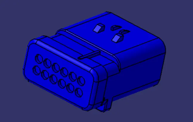
Main connector :
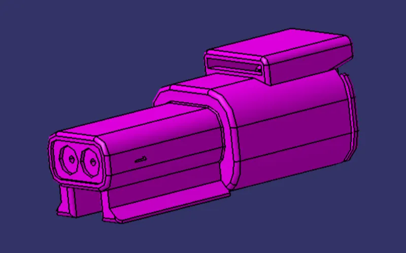
Tail lamp and indicator lights connector :
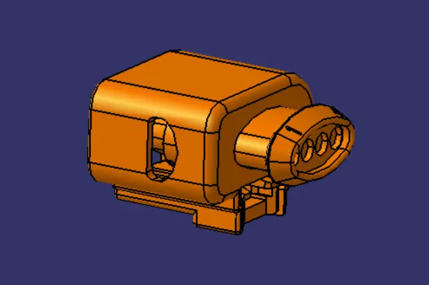
Wiper motor connector :
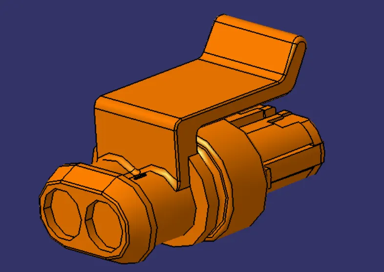
Number plate light connector :
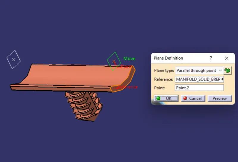
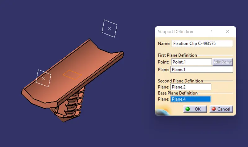
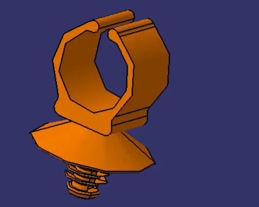
Define Clips in CATIA V5 :
- Download connector 3D
- Create required geometrical parameters
- Define as support
- Define first point, first plane,second plane and base plane.
- Do again for the opposite side.
Catalogue creation :
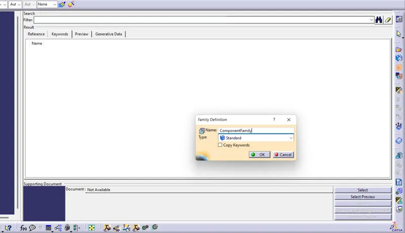
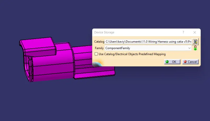
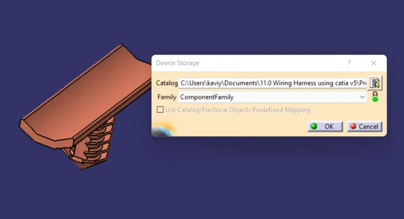
Next step is to create the two catalogue for the connectors and support system and for the cot tube. After create the catalogue for standard family add the all connectors and clips to it as shown in the figure.
Wiring Harness creation :
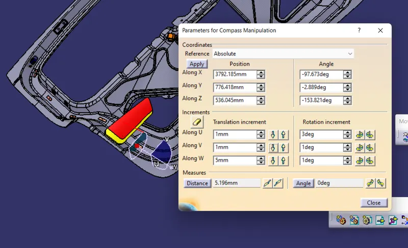
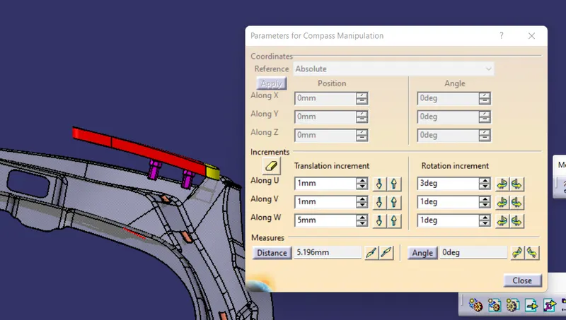
First step is to create the new product file and save it some location. and add the car back door assembly in that product and create another product file in that and name is as the geometrical bundle and save in the same location. And add the all required connector and the clips from the catalogue flie we crated. And move the connectors for the required places in the door panel as show in figure.
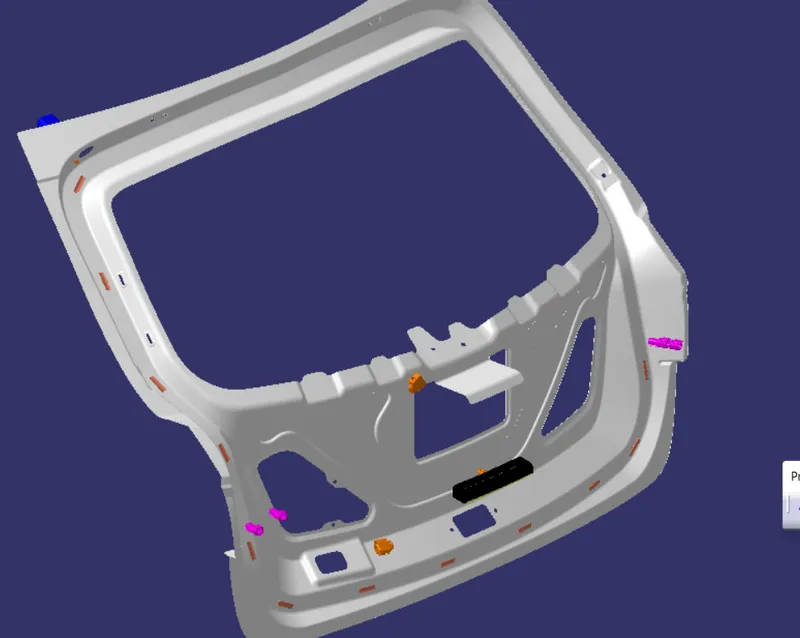
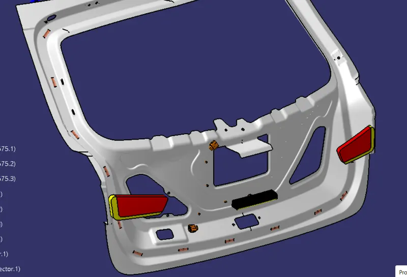
Geometrical Bundle creation :
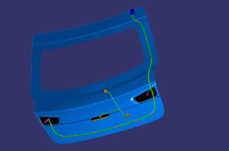
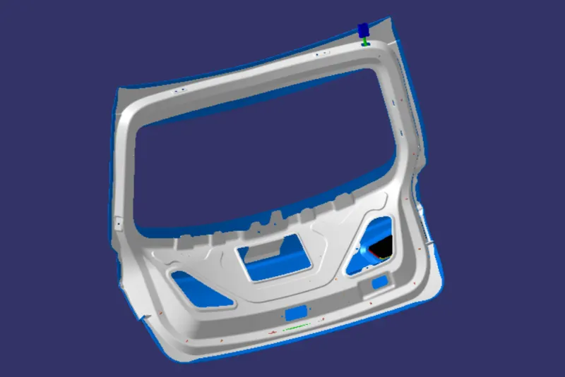
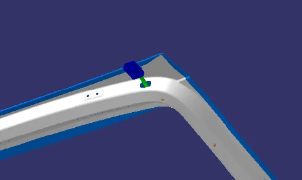
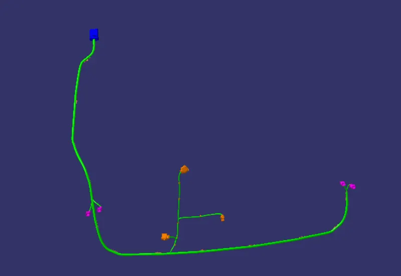
After assemble and move the connectors to the desired location next move to the electrical harness assembly workbench and create the routing the main connector to all other connectors as per the packaging rules we have study in the course. And by using the fixation clip for the 10mm wire and fir tree clip for the 5mm bundles. and routing through the fixation clip we provided in the inner panel as shown in figure.
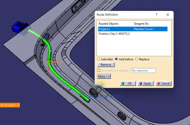
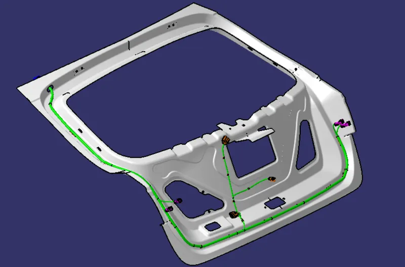
With and without Inner panel :
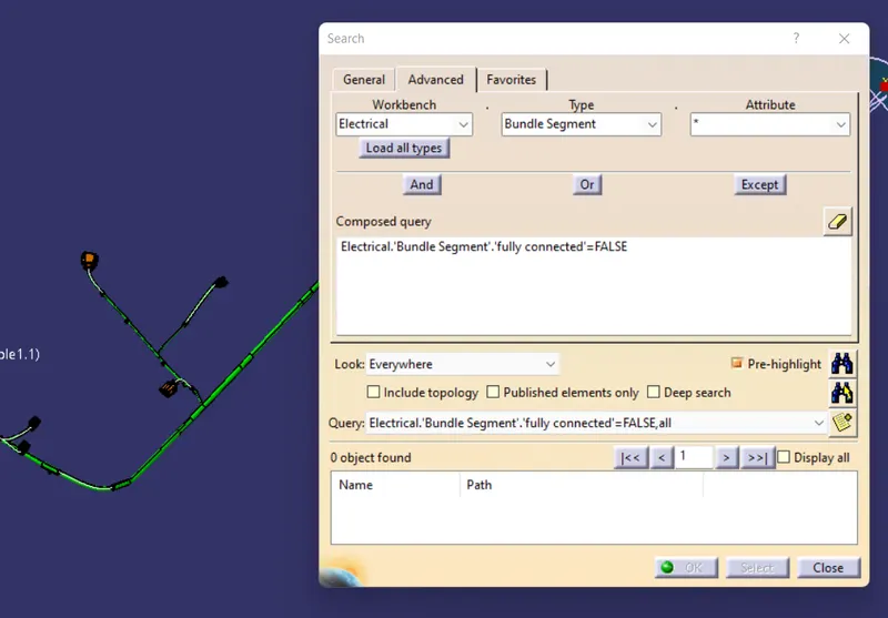
Check for Bundle connectivity :
Create Flatten Harness :
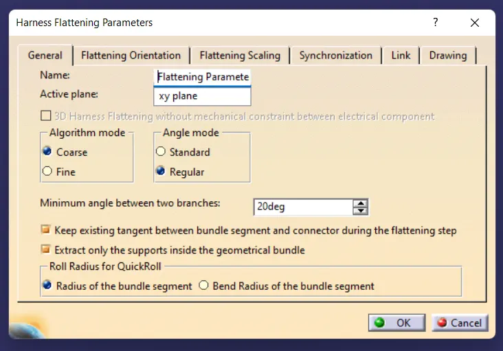
After create the bundle routing next step is to create the flatten for the manufacturing and assembly process. first open the new product and save the file and define the parameters box first as per the requirement as shown in figure. And add the required geometrical bundle using the extract tool in the Flatten Harness workbench as shown in the figure.
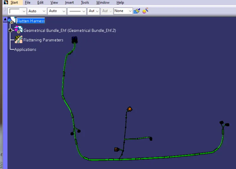
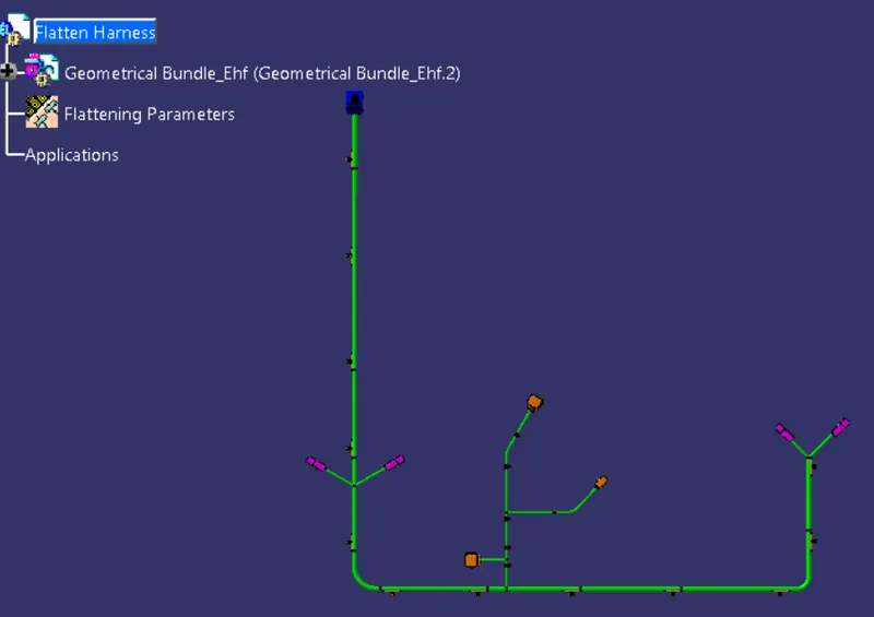
Next step is the flat the bundle by using the flatten tool in the Flatten harness workbench as shown in the figure. And rotate the connectos and the fir tree clips for the corrent position by using the assembly workbench tools. And then rotate the bundle by using the rotate and roll tool in the flatten workbench as shown in figure. and save the files in the proper location.
Drawing file creation :
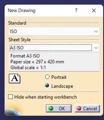
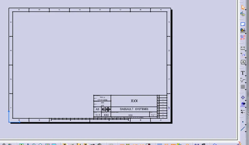
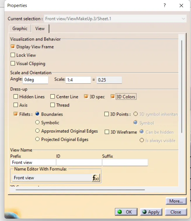
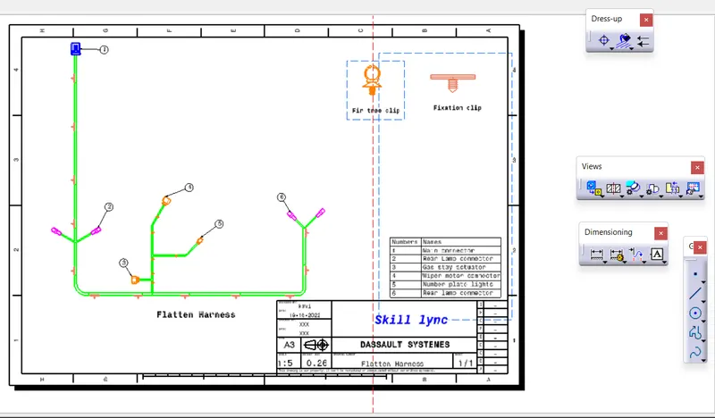
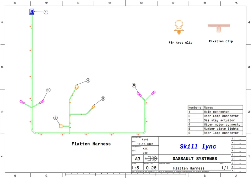
The next step is to create the drawing file from the flatten harness file. For the we need to open the drawing file and select the proper paper size and add the front view for the drawing file from the flatten harness file. and modify some properties for the drawing file and add the title block and the components name list on it. And save the file as the drawing file and also as the PDF file as shown in the figure.
PDF file :
Conclusion :
Hence the wiring harness on the car Back Door Assembly is successfully done by concidering the all packaging rules, industry best practies and apply the production covering to the required wiring. And also the flatten Drawing for wiring is also created successfully done.