Project 1
Engine wiring Harness
Aim :
To route the wiring harness on the 16V type engine by concidering the all packaging rules, industry best practices and apply the production covering to the required wiring. And finaly prepare the Flatten Drawing for wiring.
Objective :
- To create required geometrical parameters and Define all connectors and clips as Electricaly defined by using the Electrical design workbench.
- To create the product include engine and all connectors in that.
- To Route the wiring wiring harness as per the all packaging rules by using the Electrical Harness assembly workbench.
- To create the Flatten Harness and create the Drawing file from it.
Introduction :
The automotive wiring harness is referred to as the central nervous system in the vehicle. It mainly consists of an electrical harness and the mechanical harness in the design. The current project is focused on the mechanical harness in the design. The current project is focused on the mechanical wiring harness and its rules and procedure to be followed while routing in the virtual condition. CATIA V5 electrical workbench is used as the CAD tool for routing the wires in the engine and tailgate components.
Wiring harness terms :
Wiring harness is the assembly of different systems, sub-systems in the vehicle. It won't have any function. It depends on its system and sub-system. It used to pass the signals between components.
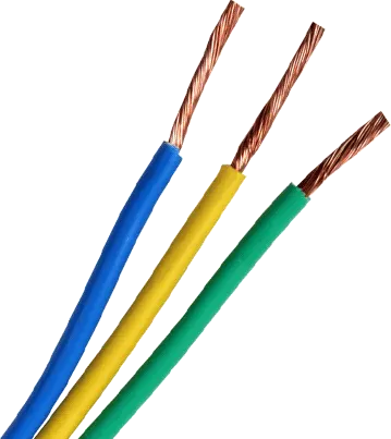
1.Wires : Wiring harness consists of various wires bundled together, with each individual wire responsible for carring electric signals and energy used in starting the engine, lights, meters, navigation system, power windows and Doors and other devices in the vehicle. Wires are Cu conductors insulated with PVC insulation.
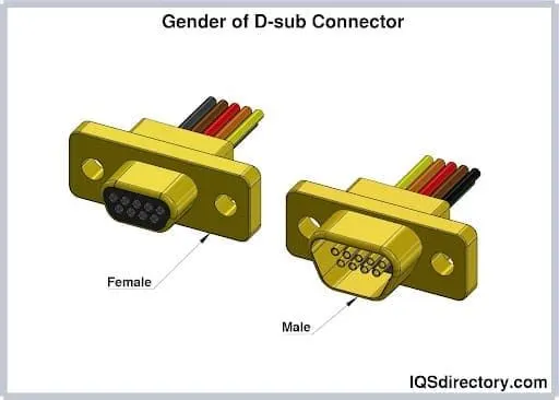
2.Connector : An electrical connector, is an electro-mechanical devices used to join Electrical termination and create an electric circuit. Electrical connectors consist of housing, Terminal, Wedge Locks, Seals, Cavity Mounting Cam etc., Connectors are plastic moulded housing with locking and retention features.
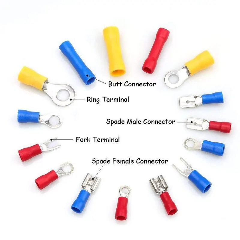
3.Terminals : Terminals are defined as A device designed to terminate a conductor that is to be affixed to a post, stud, chassis, another tongue, etc, to establish an electrical connection. Terminals are metal (brass) conductor with plating (tin, silver, gold) constructed in specific shape to secure the joins from the environmental conditions and with minimum electrical resistance.
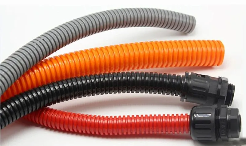
4.Protection device : Corrugated flexible tubes also known as Cot tubes/convoluted conduits have a wide range of application in automotive industries. Corrugated tubes are made from plastic material and they are flexible. Production covering are flexible, temperature, wear and tear resistant moulded plastic/polymer parts.
Some other productive devices : Gromments, insulation tapes, cotton tapes
Engine Wiring Harness :
Procedure :
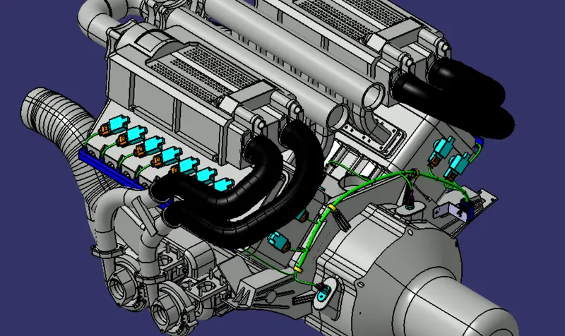
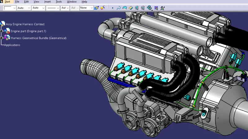
In this project we going the route the wiring harness for the 16v type engine by concidering the all packaging rules and the industry best practices. the eigine 3D model is shown in figure.
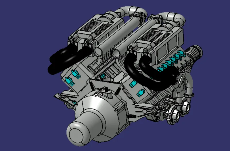
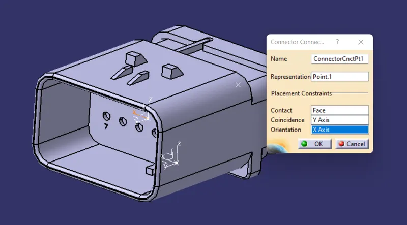
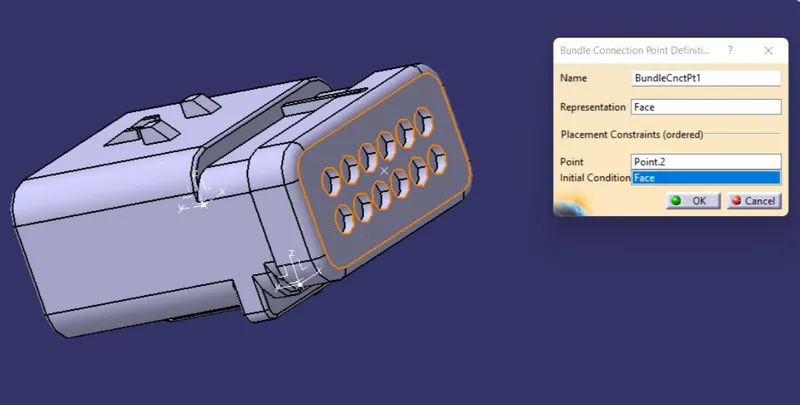
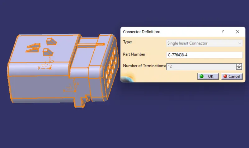
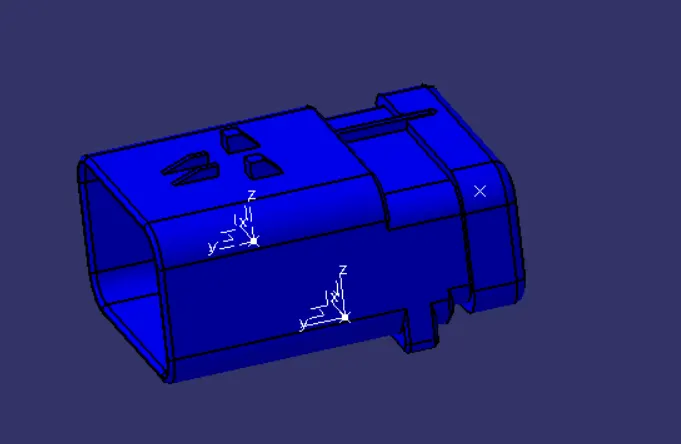
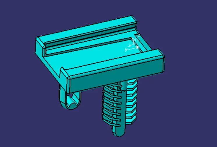
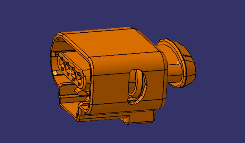
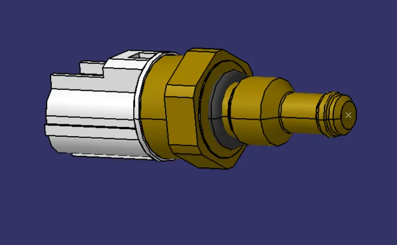
This engine model has 8 injectors in one side and another 8 injectors in another side so totally 16 injector connectors we need to connect and has 4 cam connectors. And then one coolent temperature sensor and one nutral position sensor and one engine speed sensor is pressent. And we need to connect all connectors by routing the wires for that we need the proper connectors for the proper sensors. And those sensors are need te define electrically by using the electrical design workbench as shown in the following figures.
Main connector :
Fir tree for support main connector :
Injector, cam connector :
Coolant temperature sensor connector :
Nutral position sensor connector :
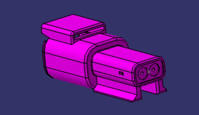
Engine speed sensor :
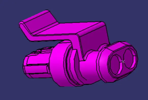
P Clamp :
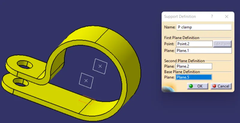
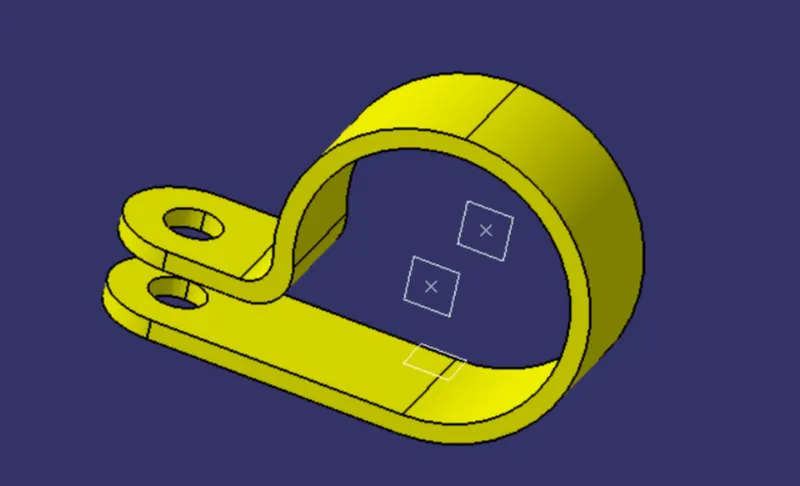
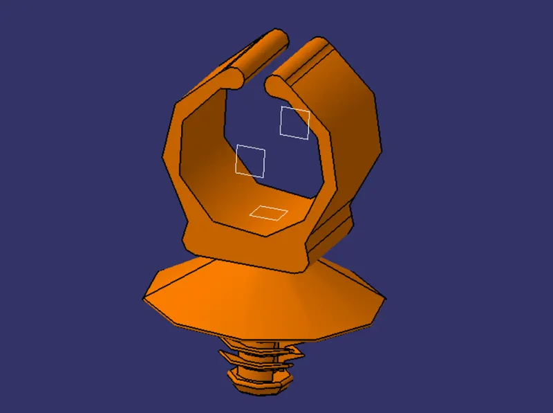
Clips :
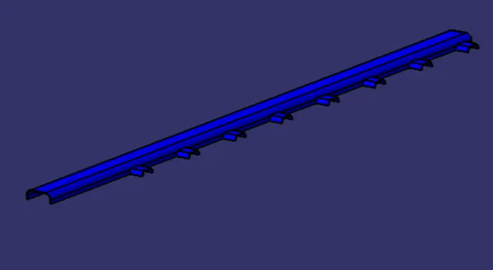
Channel Top :
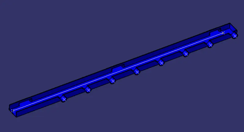
Channel Bottom :
Creation of Catlogue :
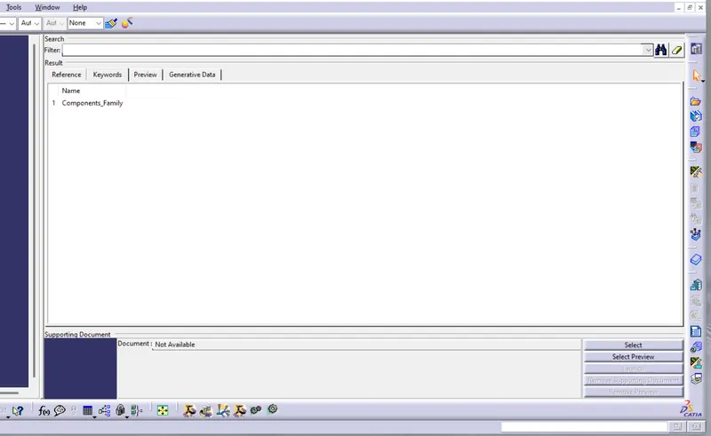
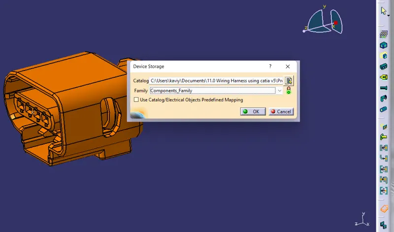
Then next step is to create the catalogue for add the all component in it so create new file for catalogue document include the standard family name as components family and save that file. And open the each component which is need in the harness add to this family as shown in the figure.
Create New Product : Assy Harness
First create the new product in the product assembly workbench and add the engine lite file into this assembly. and after that create anothe product file inside this assy harness file and add the required connectors and the channel equipments by using the compass and manipulation tool and smart move tool in the part assembly workbench as shown in the figures.
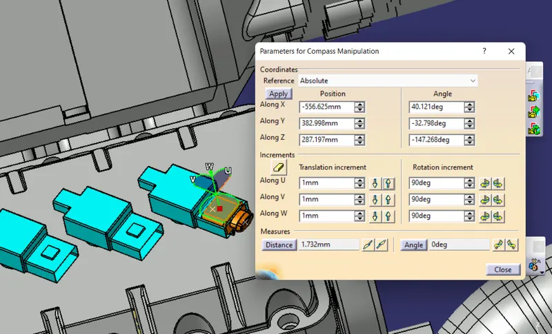
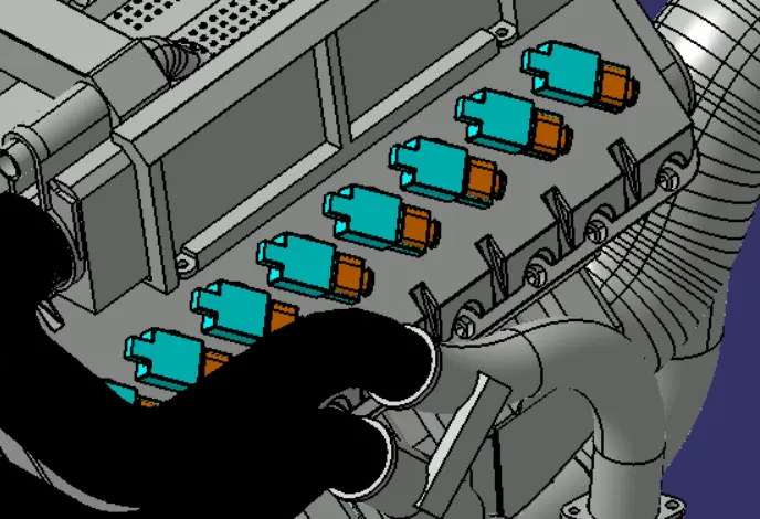
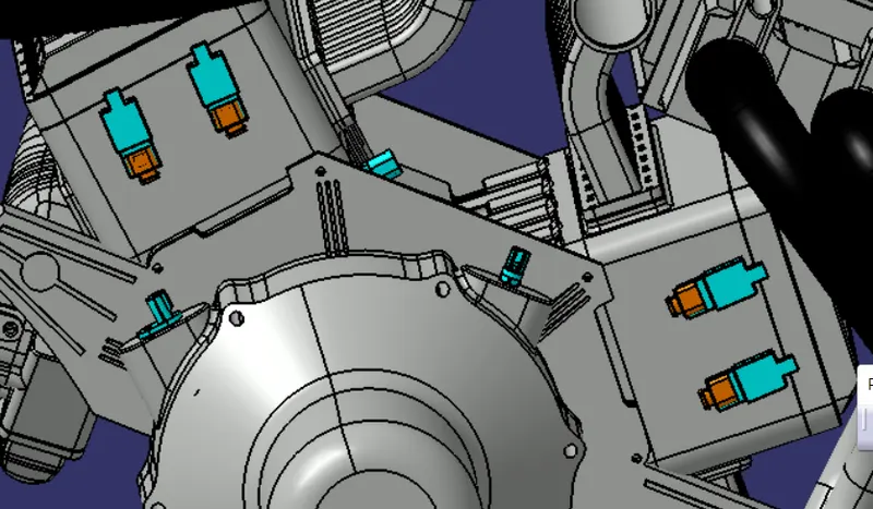
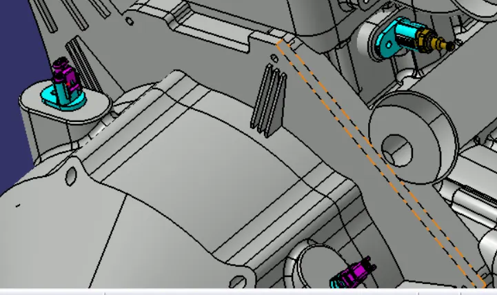
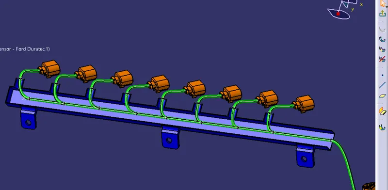
After place all connectors in the required position next step is to place the main connector in place and routing the all connectors using the p-clamps and the clips routing to the main connector. And for the injectors connectors it have some small area to route the wire and that place is more heat is produced so we going to add the channel for routing the injector connectors as shown in the figures.
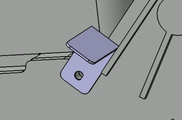
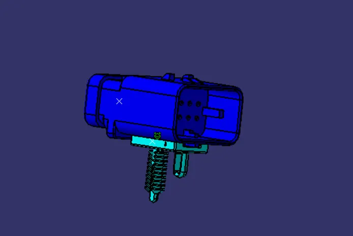
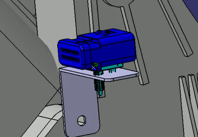
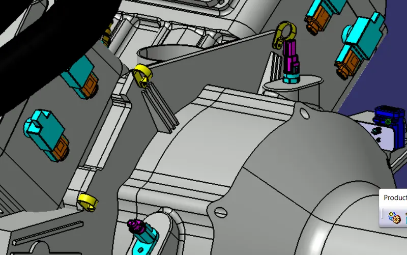
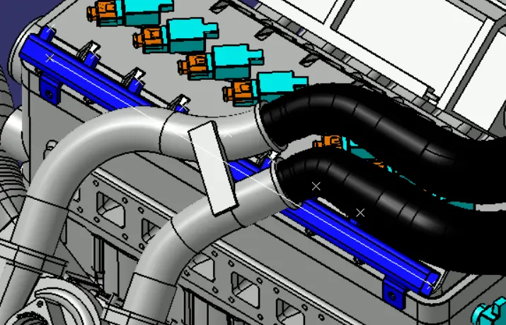
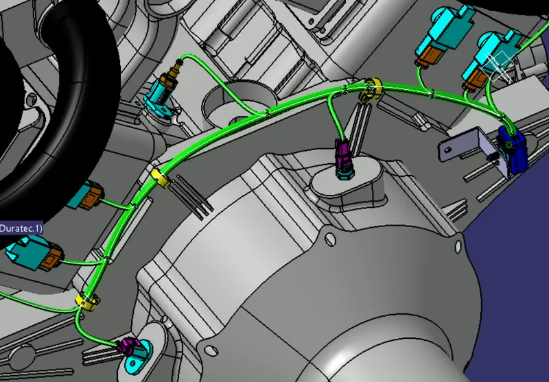
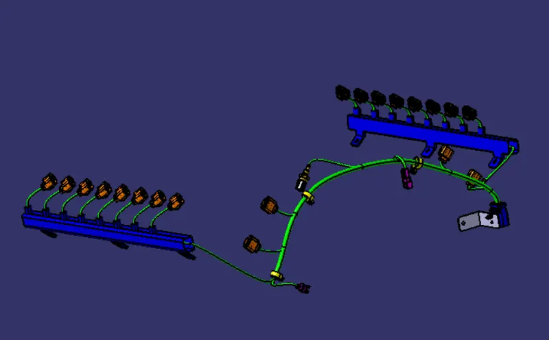
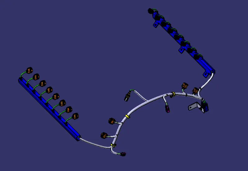
Next step is to routing the bundle harness through the connectors and p-clamps and the channel we added into the product assembly by using the Electrical Haress Assembly workbnech and also we add the productive corrgated tube as 15mm and 10 mm and distance from the connectors is 20mm taken as shown in figure.
Creation of Flatten Harness :
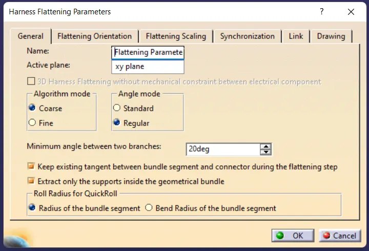
After creation of the product for the electrical harness we need the create the Flatten file for move the prodection and assembly section. So for create the flatten patten first open the product file in the Electrical Harness Flattening workbench and first step is to set the parameters first as shown in figure. And add the Geometrical bundle of the required harness to be flatten file by using the extract tool in the Flatten Harness workbench as shown in figure.
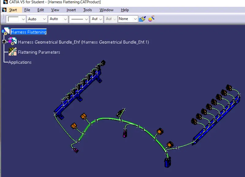
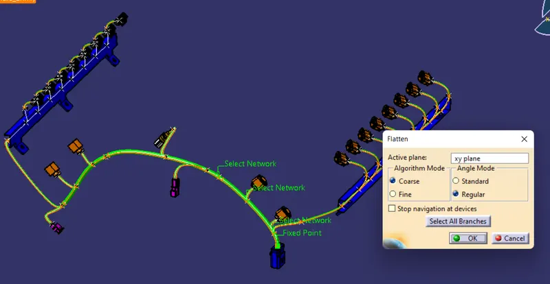
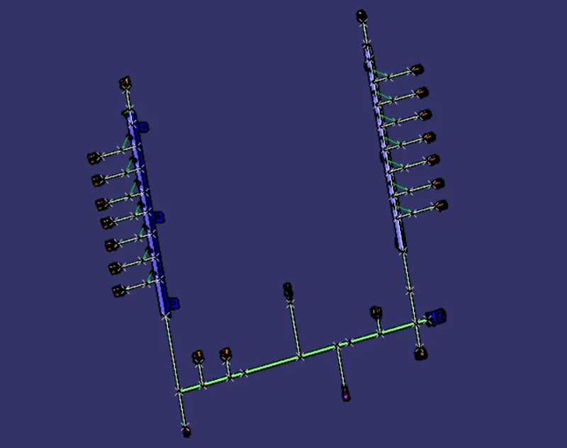
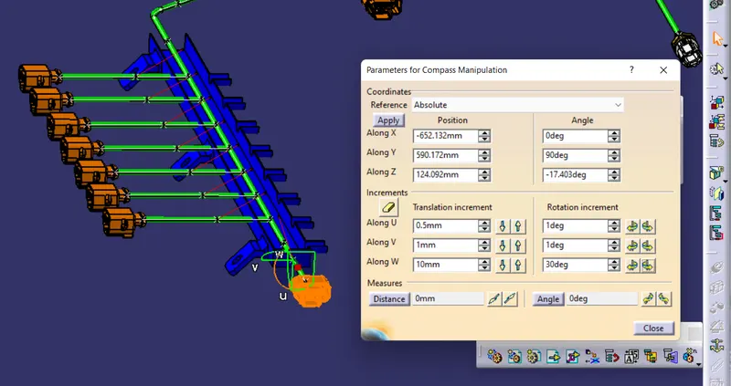
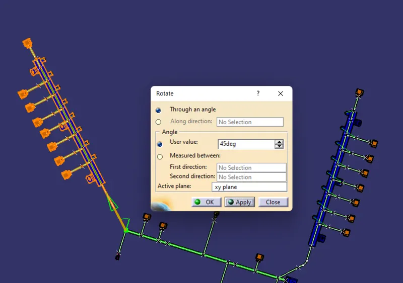
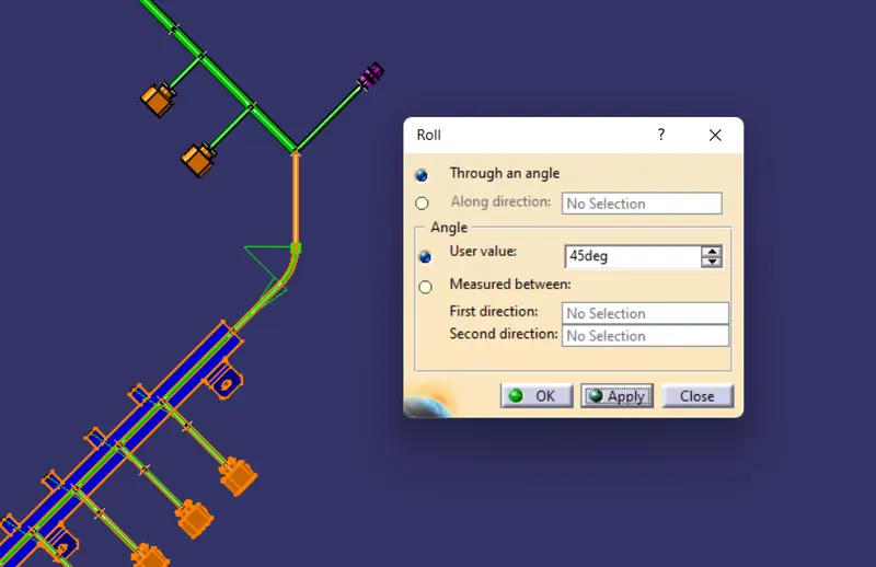
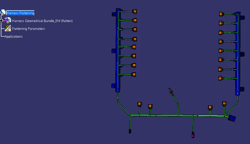
Next step is flatten the bundle by using the flatten tool in the Harness Flatten workbench as shown in figure and rotate the connectors for the correct position by using the Assembly workbench and the compass tool properly. And by using the Rotate and roll option align the bundles properly as shown in figure.
Creation of Drawing :
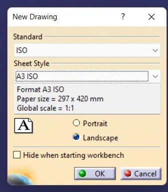
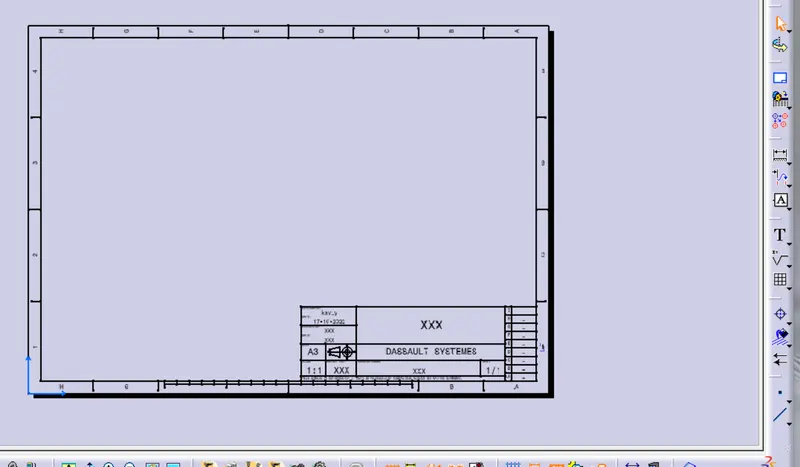
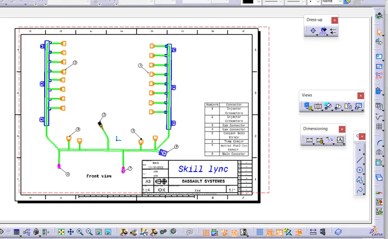
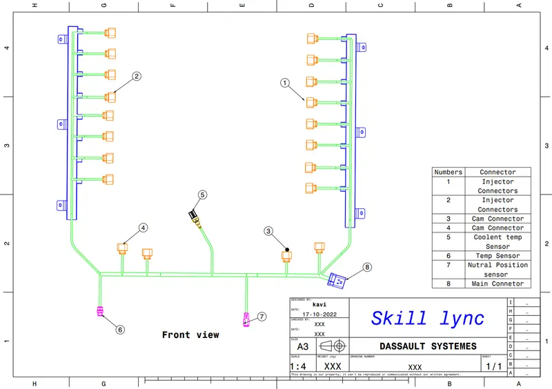
After create the Flatten file next step is to create the Drawing file for wiring harness file. open the new Drawing file as shown in the figure as the A3 size and iso Standard file. add the title box for it and change some changes in the parameter box as shown in figure. by using the front view tool in the Drawing file add the Flatten file.
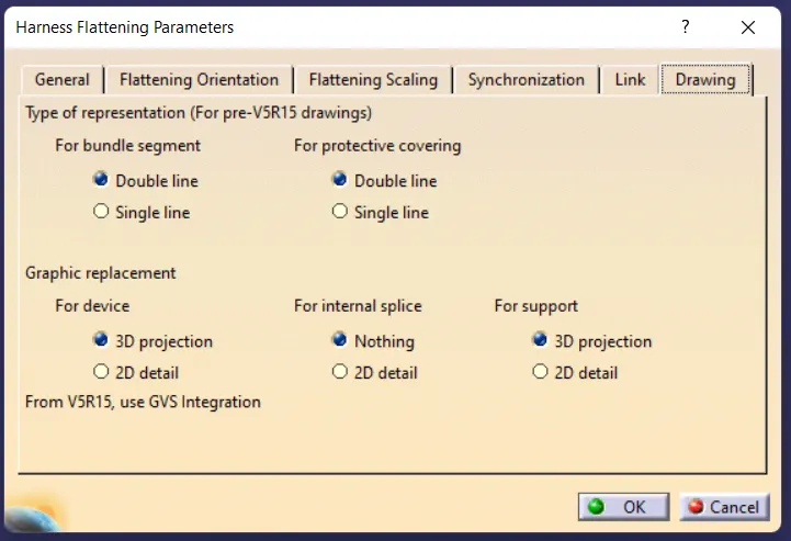

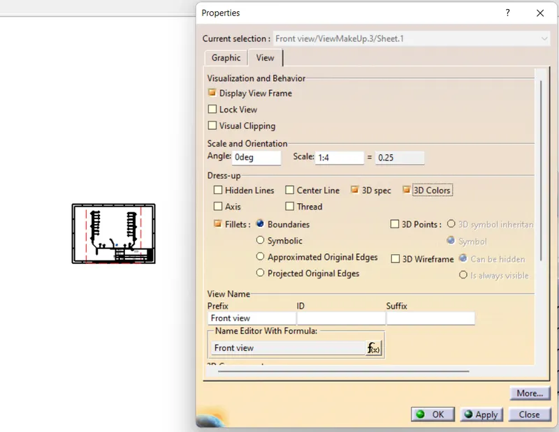
After add the flatten view in the Drawing file edit some properties in the Drawing properties box as shown in figure and add the connector details as shown in figure.
Save As PDF file :
Conclusion :
Hence the wiring harness on the 16V type engine by concidering the all packaging rules, industry best practices and apply the production covering to the required wiring is done successfully by using the various workbench in the CATIA V5. And preparing the Flatten Drawing for wiring is also done successfully and save it as the PDF file.