Wiring harness design in CATIA V5 - 3D modeling Week 5 & 6 Challenge
Route the Harness layout in Electrical workbench
Aim :
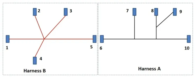
To route the given harness layout by using the required connecters and for the given maping in the electrical workbench in catia v5.
Objective :
- To define the 3D models as electrically defined in the electrical design.
- To create the routeing as per the Harness A and Harness B in the electrical workbench.
- To connect the two harness in one product file.
- And finally check for the Bundel connectivity, annotations, bundle warning and export as the .igs file.
Procedure :
For electrically define :
- Create some geometry parameter using part workbench.
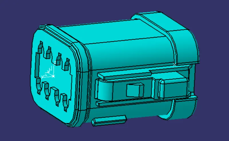
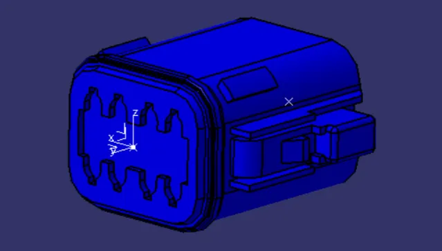
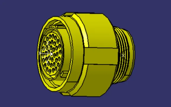
- Define as the connector in the electrical design workbench.
- Define connector connection point.
- Define Bundle connection point.
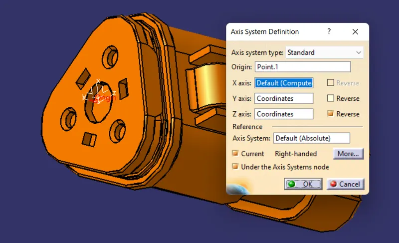
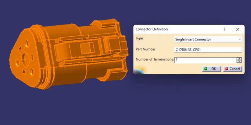
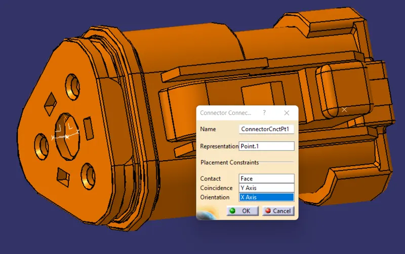
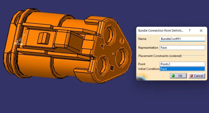
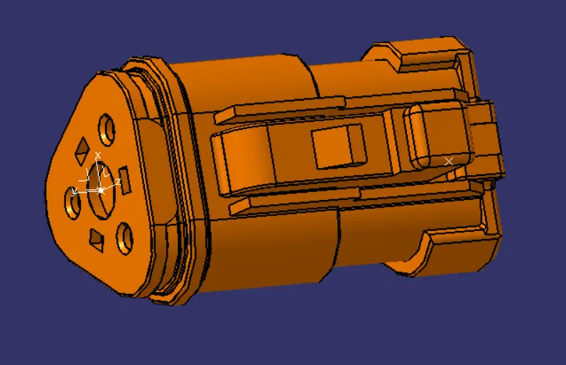
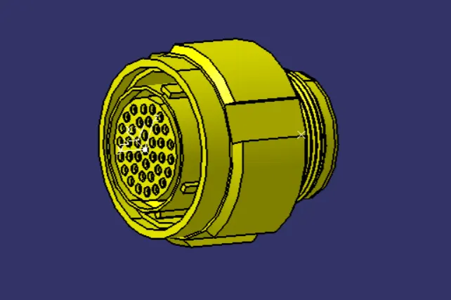
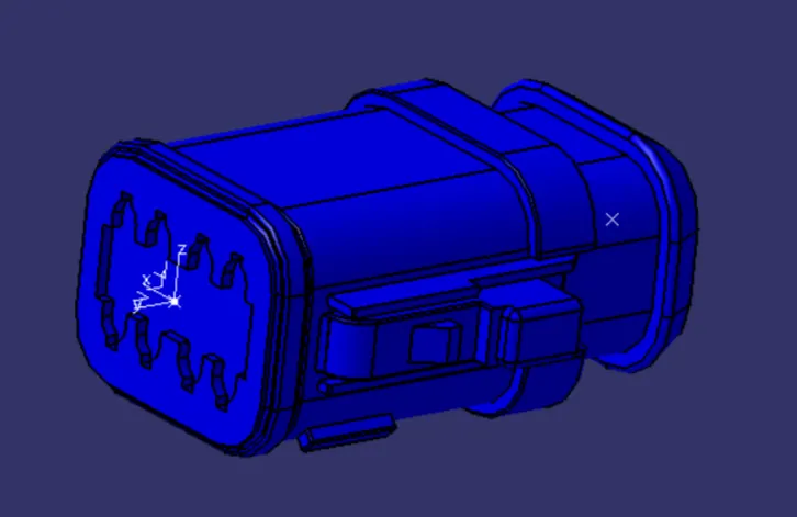
All Connectors Electrically defined :
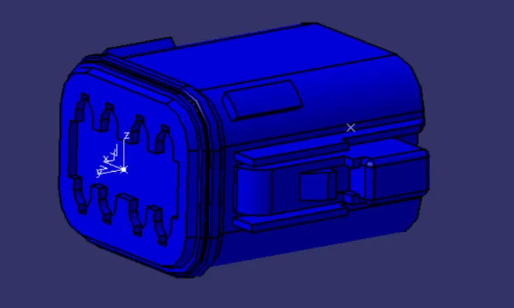
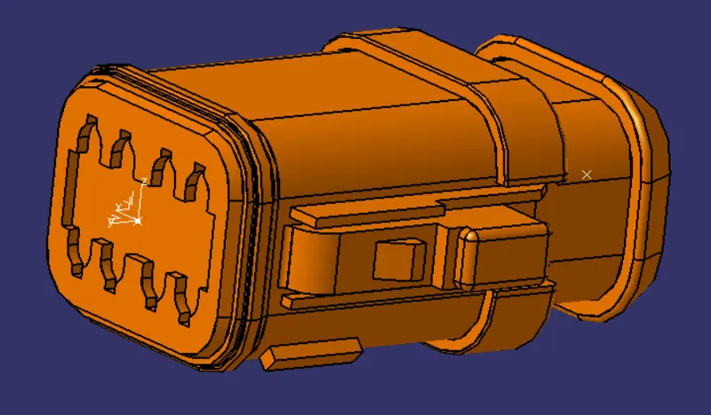
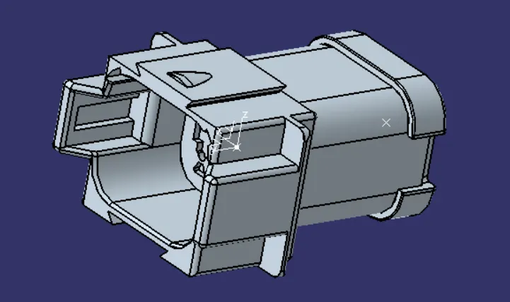
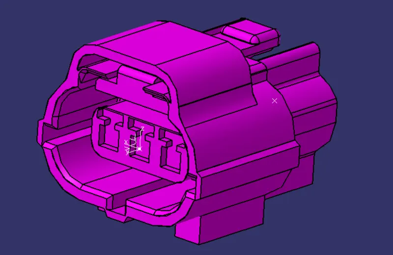
Create catalogue and add the connectors :
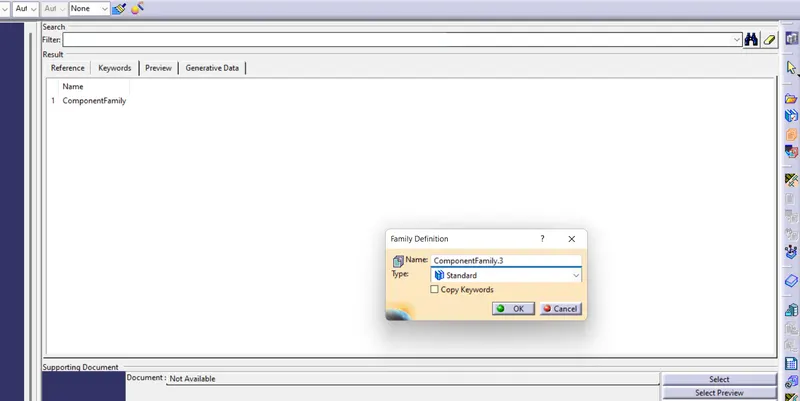
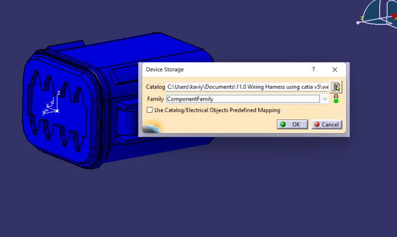
For create the catalogue click new > catalogue document and add the one family. And add the all connectors in that file as shown in figure.
Create Harness B :
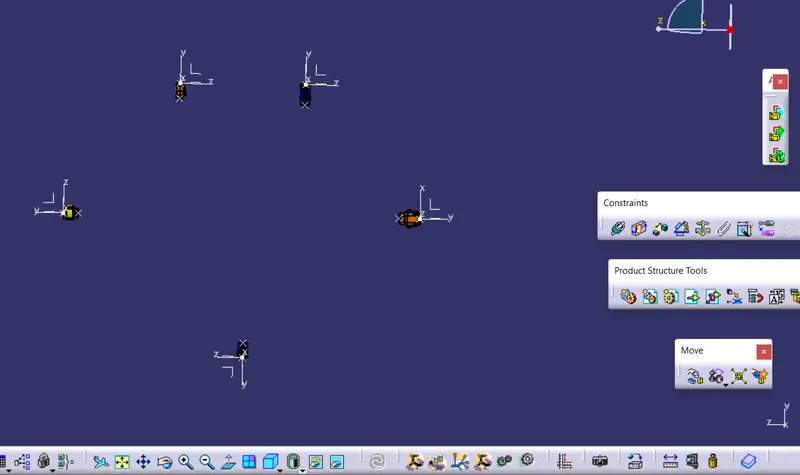
Now for create the harness B first create the product flie and add all the required connector from the catalogue we created. Next step is to move the connectors for the required location as followed by the Hasness B mapping as shown in figure.
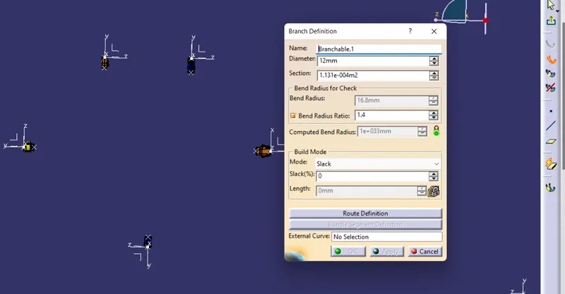
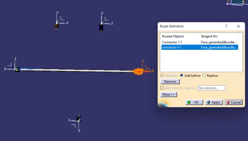
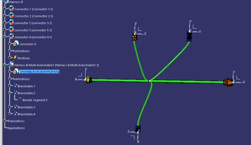
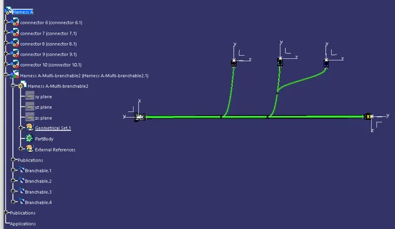
Next move the electrical harness assembly workbench and make the product file as the electrical defined by add the multi-bundle geometry option. And then using the branch definition option create the route for the Harness B as shown in figure.
Harness B :
Harness A :
Create the annotation :
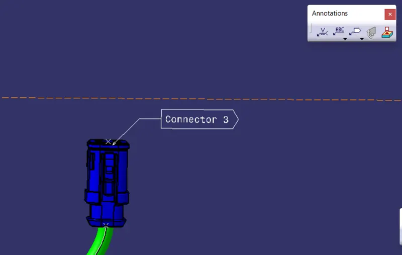
Next step is to create the annotations for the connectors as we can easily identify the connector names as shown in figure.
Make the final assembly file :
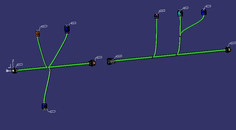
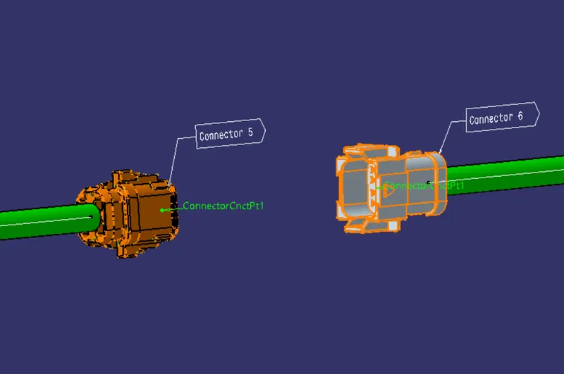
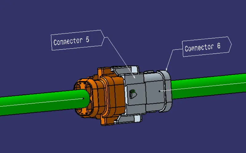
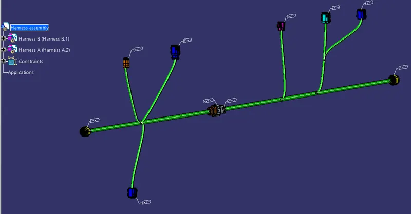
Now create the another product file and add those two harness files in that file and by using the electrical assembly workbench conect the two different Harness model by using the Connect electrical device option as shown in figure.
Check for Bundle conectivity :
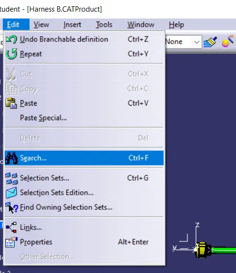
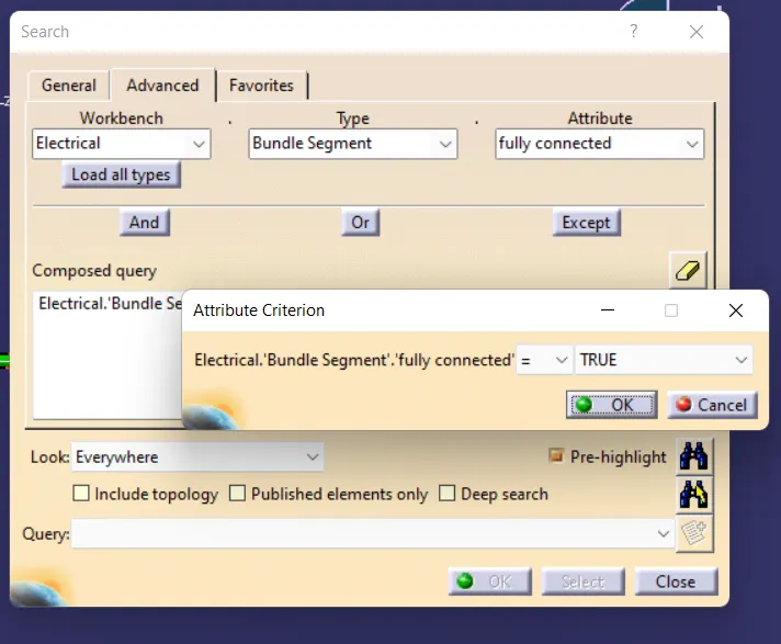
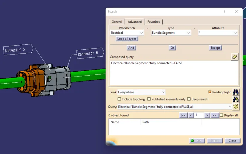
For check the bundle is electrically connected or not by using the edit > search option in that click for electrical, and bundle segment and fully connected as shown in figure.
Generate CAT.part and save as .igs format :
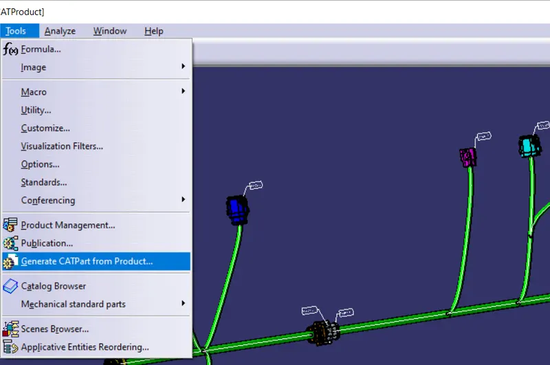
After create the product file and finish the routing for the bundle we need to generate CAT.part by using the tools > Generate CATpart and save the file as the .igs file.
Conclusion :
Hence the given harness layout by using the required connecters and for the given maping in the electrical workbench in catia v5 is done successfully done. And after create harness assembly check the bundle conectivity is also done successfully. And also given all required annotation for all connectors.
Attachments :
1) CADPart file zip.
2) .igs file zip.