Advanced Sheet Metal Design Using NX Cad Challenge_7_ Metal bracket-II
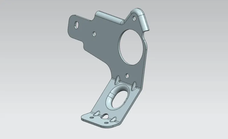
Metal Bracket 2 Design
Aim :
To design the sheet metal component of metal bracket by using the various features in the NX cad platform.
Objective :
- Design the base and flange for the metal cracket by using sheet metal features.
- Add the extra features such as advanced falnge, holes, normal cutout, gussets in the part.
- Create Drafting file unsing flat pattern.
Design Approach :
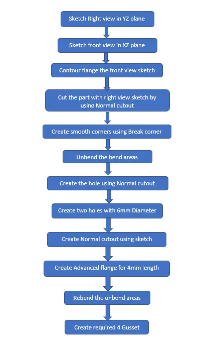
Design Procedure :
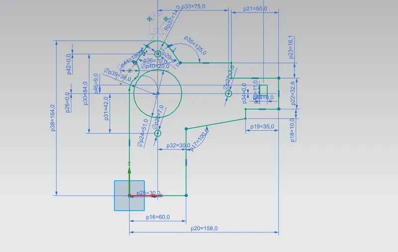
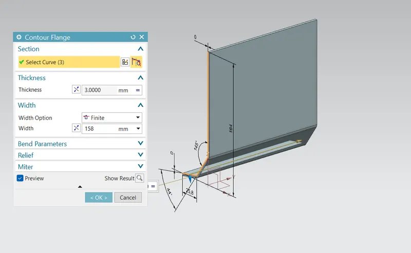
First step is to draw the 2D Drawing from the given Drafting pdf from that right view sketch in the YZ plane. And the sketch the front view in the XZ plane and contour flange the front view sketch as shown in figure.
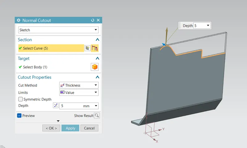
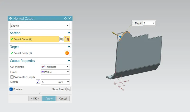
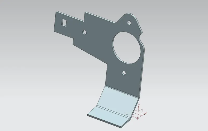
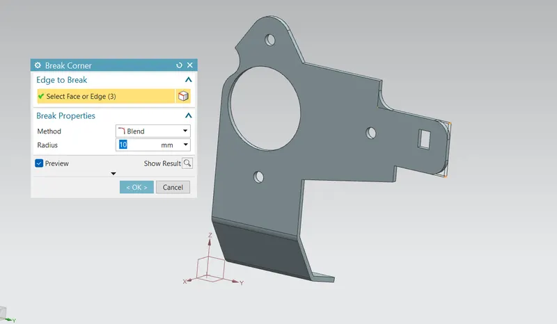
After create the contour flange then next step is to cut the not required parts fron the flange we created by using the Normal cutout feature as shown in figure. And smoothen the corner by using the Break corner feature with the proper radius value as given in the 2D drafting as shown in figure.
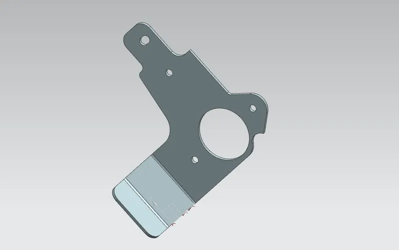
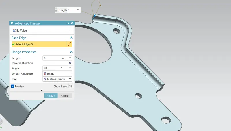
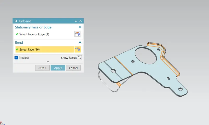
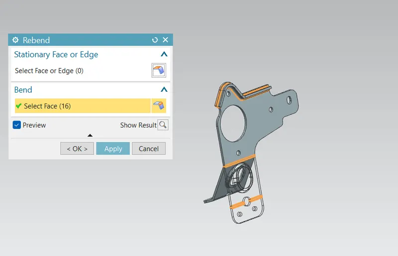
Next step is to unbend the bend areas unsing unbend tool and in the flat part creat the required sketch and cut the part using Normal cutout tool as shown in figure. After create the normal cutout then again bend the part by using the rebend tool and create the Advanced flanges as shown in figure.
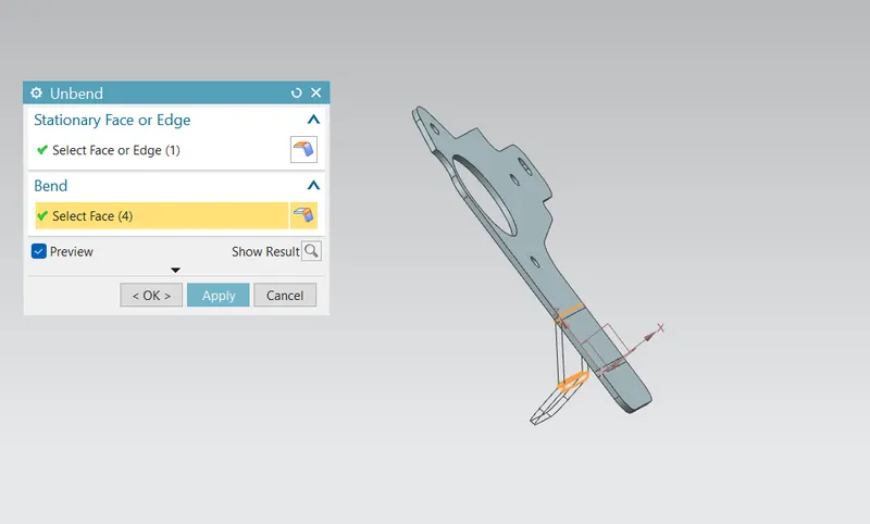
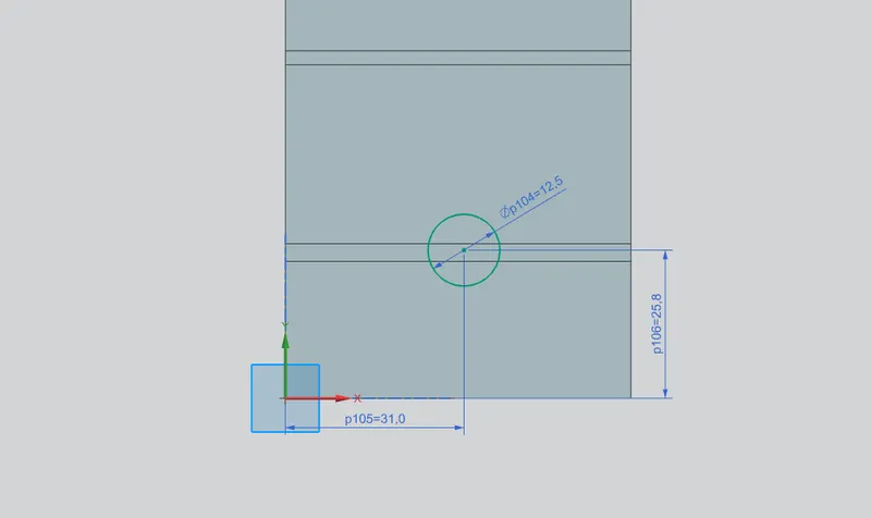
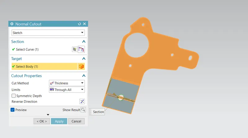
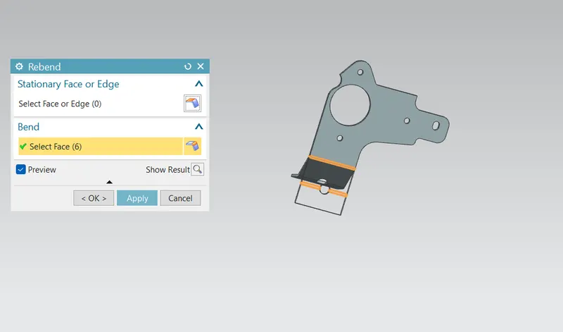
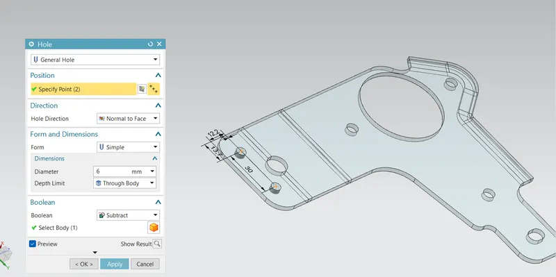
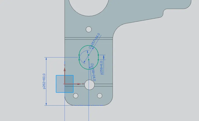
Then unbend the part and create the required two holes as shown in figure. And create the normal cutout using the required sketch as shown in figure.
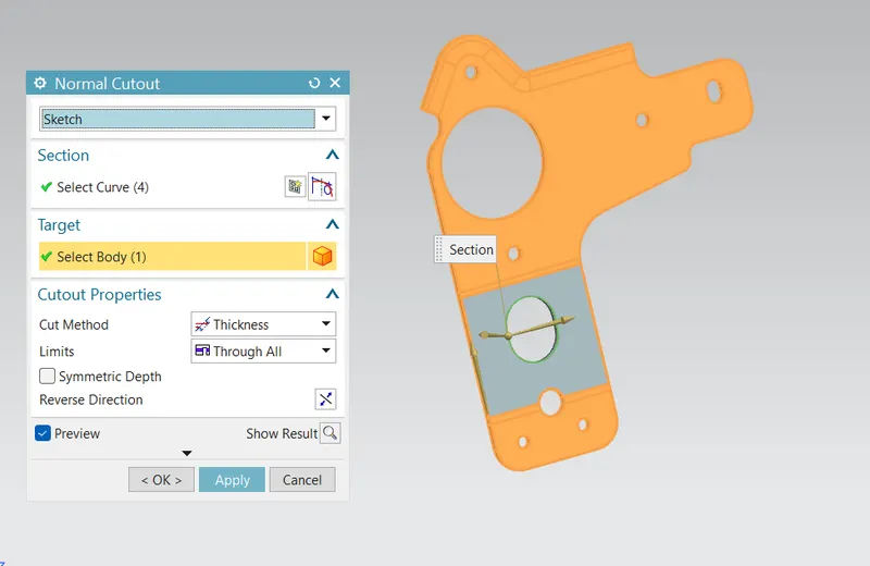
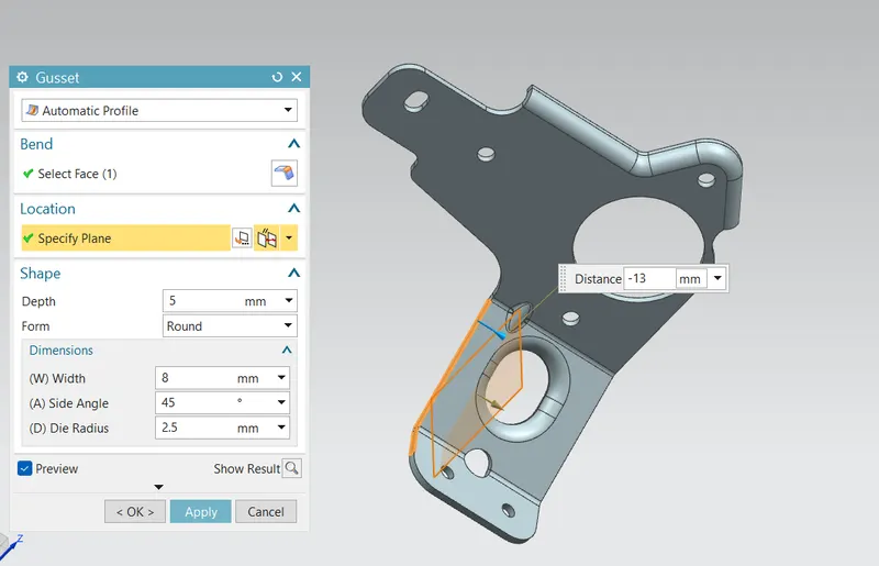
And create the Advanced flange for the length of 4mm as shown in figure. And rebend the flat part for create the next feature called gusset as shown in figure.

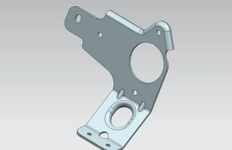
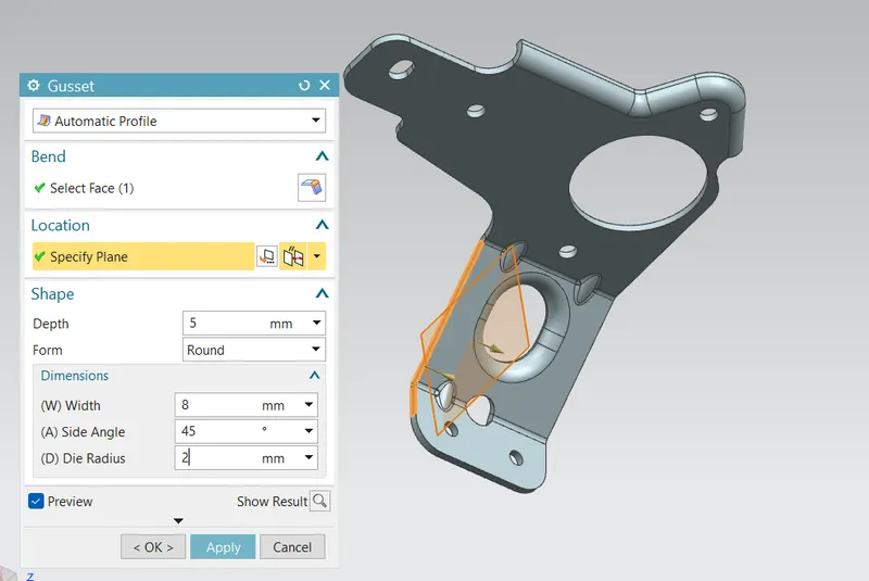
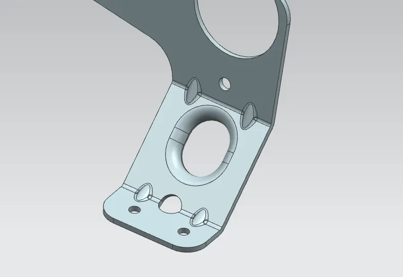
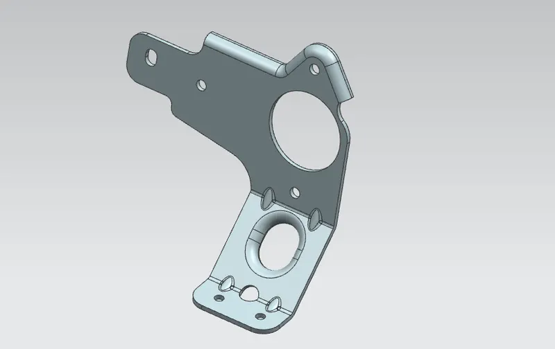
The final step is to create the four gusset in the required bends as shown in figure.
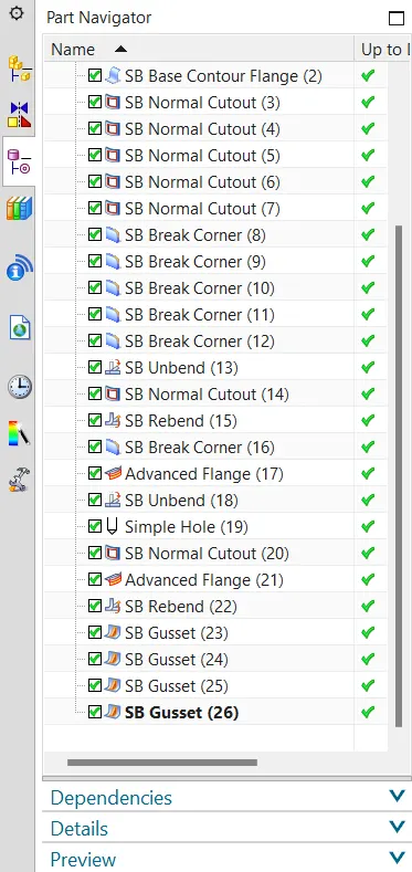
Model Feature Tree :
Create Drawing file :
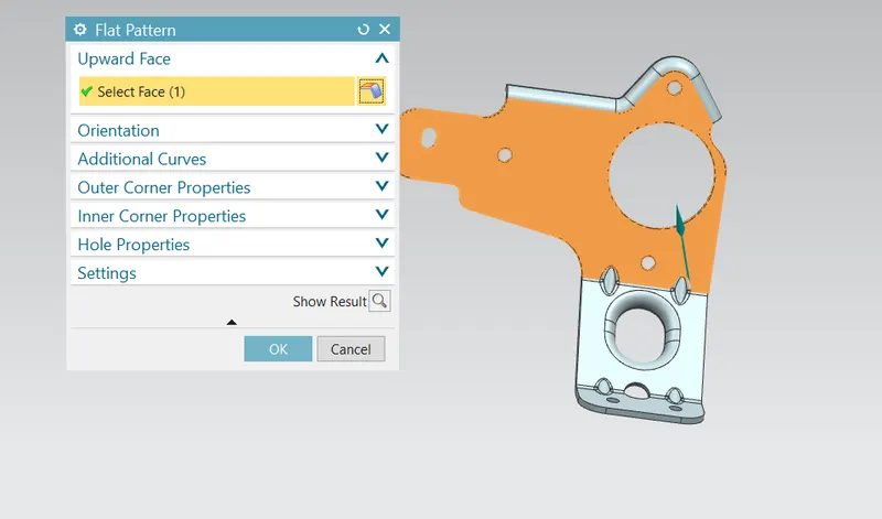
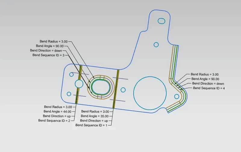
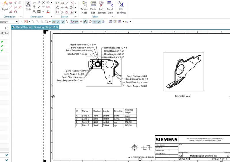
For create the drawing file for this sheet metal part first we need to create the flat solid part fot the bend part. By using the flat pattern create the 2D drawing and also added the bend table as shown in figure.
Different views :
Front view :
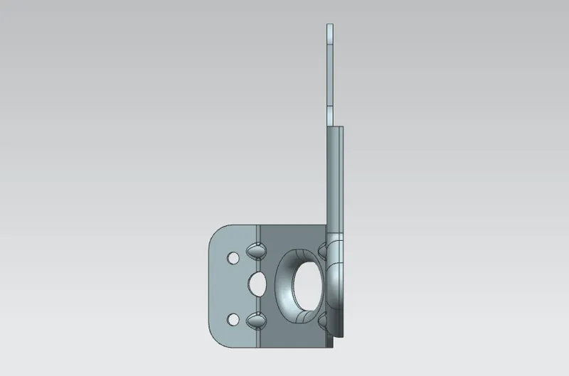
Side view :
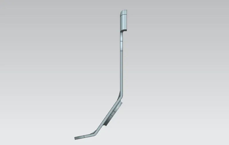
Top view :
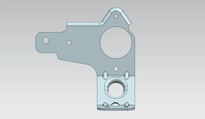
Bottom view :
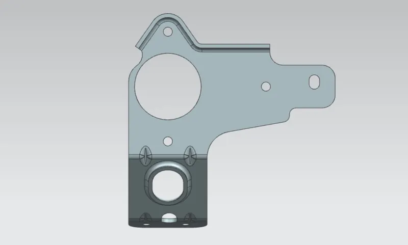
Iso-metric view :
Conclusion :
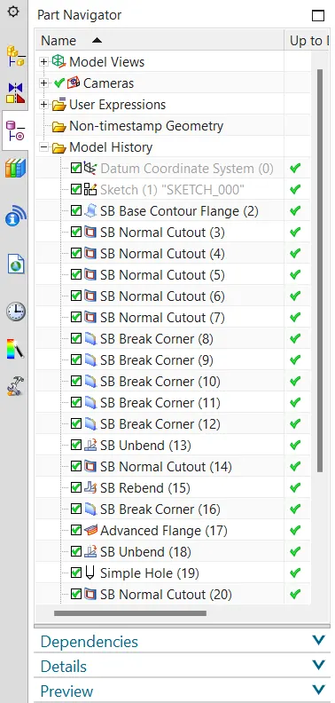
Hence the sheet metal component of metal bracket is created by using the various features such as Advanced flange, Normal cutout, Hole, unbend, Rebend, Gusset is successfully done in the NX cad platform.