FINAL INDEPENDENT PROJECT
Windshield wiper simulation
Aim:
To create model and assemble the windshield wiper assembly and analysis the wiper movement.
Objective:
- To create the 3D part of the windshield parts using part workbench.
- Then assemble the parts of wiper assembly using assembly workbench.
- Simulate the wiper movement to the required angle value using motion analysis workbench.
- solve for the maximum angle of wiper movement as required.
Theory:
Windshield wiper blades are used in the cars for clean the windshield glass while raining. This wiper blades are responsible for keeping your windshield clean. They work like a squeegee in back-and-forth motion they wipe water, snow, wiper fluid and other liquids or debris off the windshield. Windshield wipers are operated by an electric motor. The electric motor is attached to a worm gear, which transmits the necessary force to a long rod that sets the wiper arms in motion.
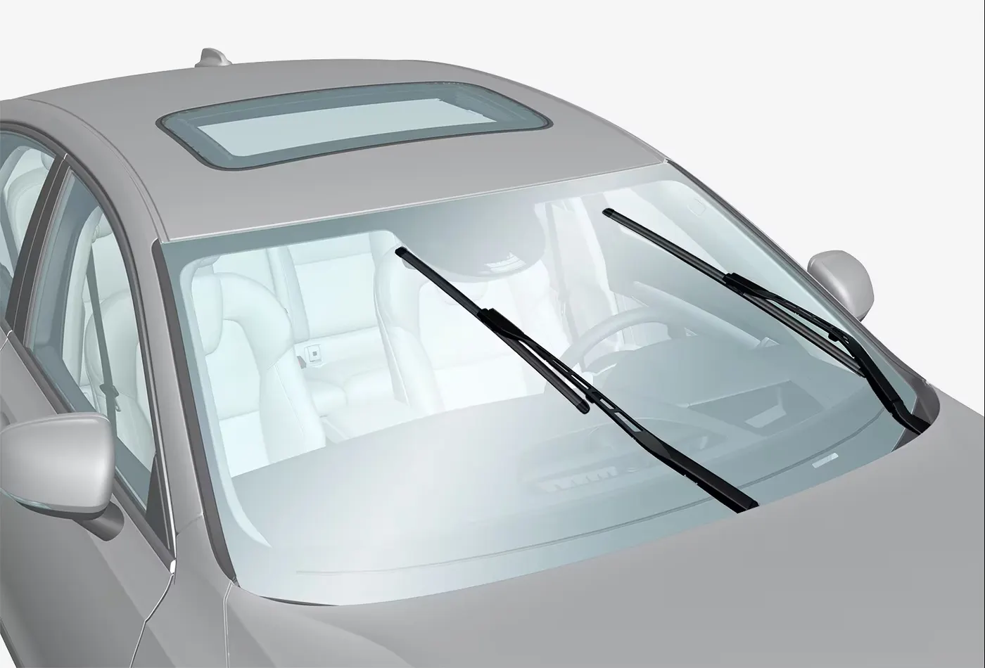
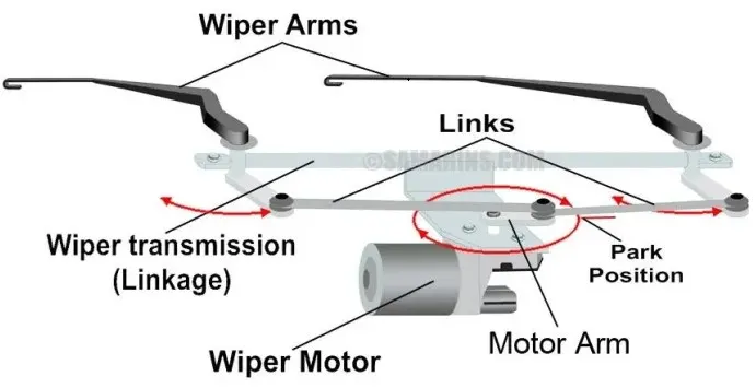
The worm gear is able to generate the force required to move the wipers as fast as they need to move. The arms move the actual windshield wiper blades. The blades are made of rubber and must apply enough pressure to the windshield in order to remove all moisture without any streaks. The arms attach to the middle of each wiper blade, and each wiper blades have several arms that distribute the pressure onto the windshield evenly.
Windshield wipers are basically the same on every car. They have two pivot points that work together to remove moisture. This is called the tandem system, and it provides the most coverage to clean the area of the windshield through which the driver looks out. There are other systems that that are used. These include the single arm system in which a single arm-controlled system extends and retracts as it moves, and the opposed system that has pivot point on opposite ends of the windshield, and the wipers move in the opposite direction. Windshield wipers operate at several different speeds. There is usually a slow and a fast setting, along with several intermittent settings.
The wipers combine two mechanical technologies to perform their task:
- A combination electric motor and worm gear reduction provides power to the wipers.
- A neat linkage converts the rotational output of the motor into the back-and-forth motion of the wipers.
Parts of wiper:
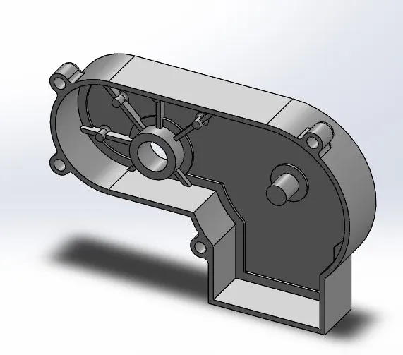
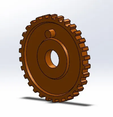
The required parts are created with the proper dimensions using part modelling workbench in solidworks software.
Main case:
Motorized Gear:
Crank:
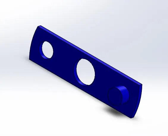
connecting rod:
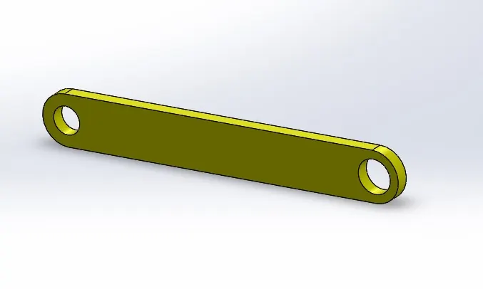
wiper crank:
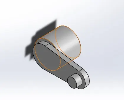
Wiper blade:
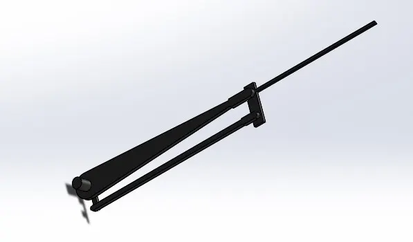
Assembled parts:
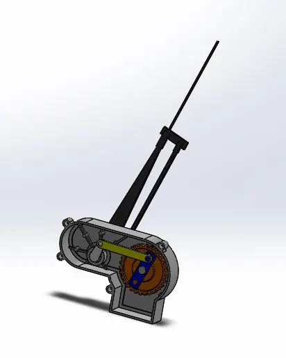
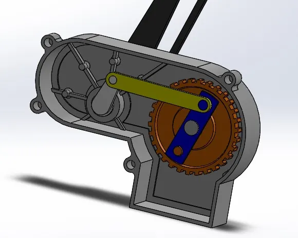
These parts are assembled in the assembly workbench using the proper mates and constrains in solidworks Sofware as shown in image.
Motion analysis:
The next step is to analysis the wiper motor assembly using the motion analysis workbench in solidworks. To analysis the wiper angle to the maximum wider as possible in what crank rod distance.
Starting setup for motion analysis:
- Motion setup frame rate set as 120fps for this setup.
- Attach the motor to the motorized gear.
- The motor speed set as 30rpm.
- Make contact between all parts in the assembly.
- Total time of analysis in 8 second.
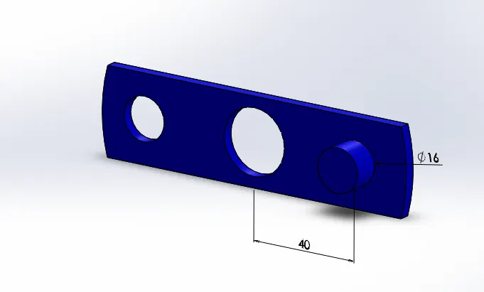
Case 1: (40 mm)
For this case 1 the crank rod pin distance is maintained as 40mm and then run the simulation by using the above motion study stating setup.
Result plot:
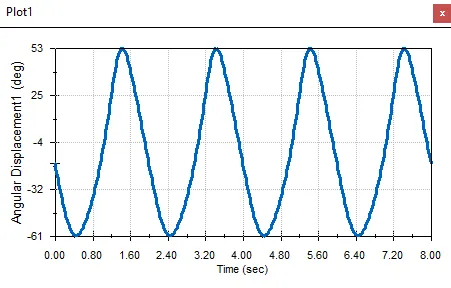
In this plot is drawn for the angular displacement of the wiper blade to the time in sec in x direction. By this plot the maximum angel moved by the wiper is 61 deg in left side and 53 deg in right side. So, the total angle cover by the wiper blade is 114 deg.
Case 2: (42 mm)
Previous case 1 the angle value is not satisfied so here we increase the distance furthermore. For this case 1 the crank rod pin distance is maintained as 42mm and then run the simulation by using the above motion study stating setup.
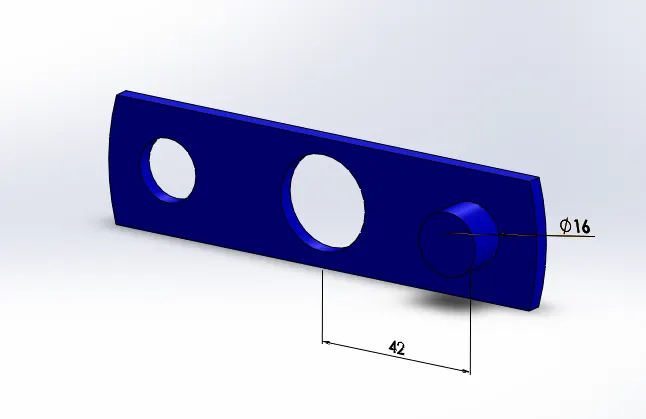
Result plot:
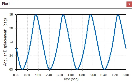
In this plot is drawn for the angular displacement of the wiper blade to the time in sec in x direction. By this plot the maximum angel moved by the wiper is 65 deg in left side and 58 deg in right side. So, the total angle cover by the wiper blade is 123 deg.
Case 3: (44 mm)
Previous case 1 the angle value is not satisfied so here we increase the distance furthermore. For this case 1 the crank rod pin distance is maintained as 44mm and then run the simulation by using the above motion study stating setup.
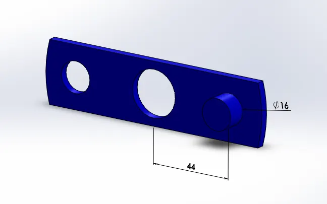
Result plot:
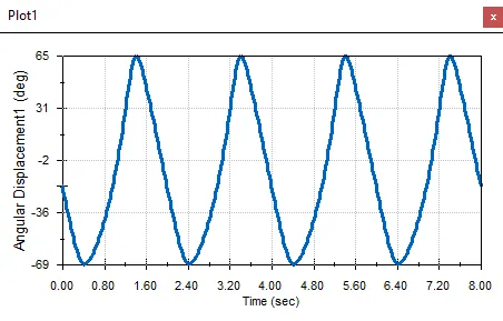
In this plot is drawn for the angular displacement of the wiper blade to the time in sec in x direction. By this plot the maximum angel moved by the wiper is 69 deg in left side and 65 deg in right side. So, the total angle cover by the wiper blade is 134 deg.
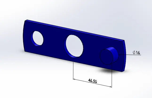
Case 4: (46.50 mm)
Previous case 1 the angle value is not satisfied so here we increase the distance furthermore. For this case 1 the crank rod pin distance is maintained as 46.50mm and then run the simulation by using the above motion study stating setup.
Result plot:
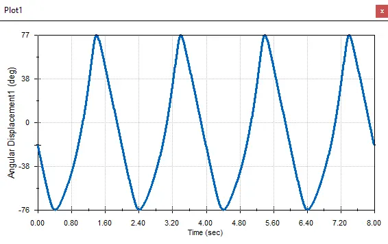
In this plot is drawn for the angular displacement of the wiper blade to the time in sec in x direction. By this plot the maximum angel moved by the wiper is 76 deg in left side and 77 deg in right side. So, the total angle cover by the wiper blade is 153 deg.
Observation and result:
From this wiper motor motion study, we can understand that the crank pin distance is related to the wiper blade angle. When the pin distance is increased the wiper blade angle is also increased. And finally increased the wiper angle up to 154 degrees this is fine for this wiper motor.
Attached files:
1) part and assembly file.
2) Motion study video.