Roof challenge
Roof Design
Aim :
To design the roof and its reinforcements from the given styling surface received. After the design is done calculate the heat distortion criteria and snow load calculations.
Objective :
- To develop the essential flanges and reinforcements using roof styling as the input.
- After design the required bow roofs to determine the Heat Distortion Criteria of the car roof.
- To determine the snow load criteria for a car roof.
Theory :
Roof :
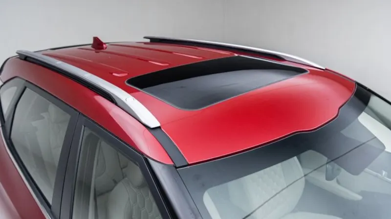
An automobile roof is the portion of an automobile that sits above the passenger compartment, protecting the vehicle occupantsn from sun, wind, rain and other external elements. Though it just looks like a styling surface that protects from sun, wind and other elements and various environmental conditions are taken into account for designing of the same. Roof should be provided with proper reinforcements for strengthening. To make the roof withstand these conditions various calculations are done. This ensures the safety of the passengers in the vehicle.
Main components of Roof :
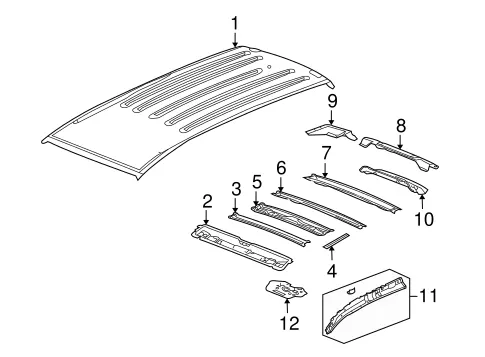
Front Roof Rail :
Front roof rails are used in the assembly of a roof in which it provides mounting provisions to windshield glasses and the changes in the front roof rail influences the frontal visibility of the passenger. The major design factor considered is the headroom clearance. The roof rail also provides provisions for mountings the inside rearview mirror.
Bow Roof :
Bow Roof is an additional stiffening member used in the roof assembly for the localised strength improvement and it is join directly to roof itself with several sport welding or even with the mastic sealent.
Center Roof :
The reinforcement center is used as a cross member between bodyside LH & RH respectively. In some cases the reinforcement center is not joined with the roof and in some other cases, it is made to join in both roof and bodyside. The reinforcement center and Bow roof are joined either spot weld or by mastic sealants and provisions for the same are given.
Rear Roof Rail :
The rear roof rail is the one of the importent component of the roof assembly which is used for the back door mountings. similar to the front roof rail it is also importent design consideration include rear passanger head clearance rear visibility of the vehicle.
Design procedure :
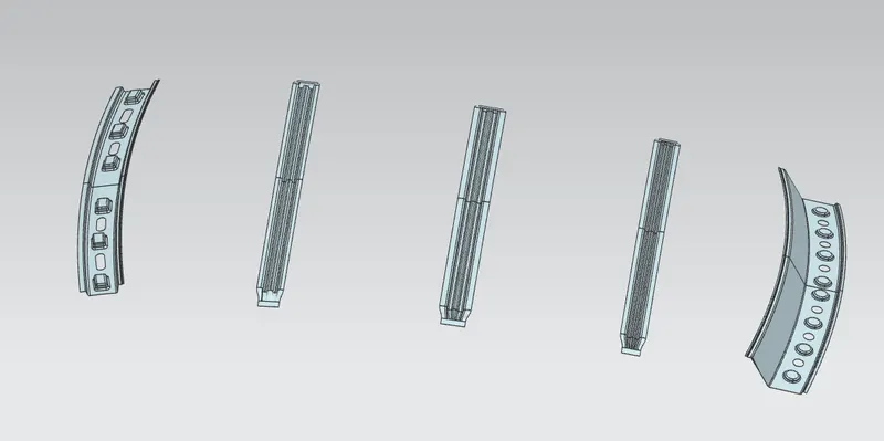
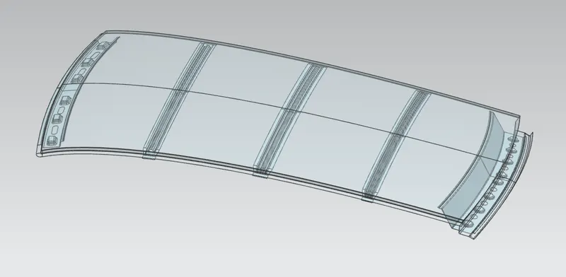
For this design process the styling part is given already so we are going to design the required reaming parts. so for this roof going to design the Front Roof rail, two Bow roof, Center Rail and Rear Roof rail.
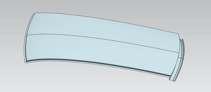
First we download the styling part model and open it in the NX cad software. and from that we take it as the reference and create the other parts such as front roof rail and bow roof. That styling part is looks like as shown in figure.
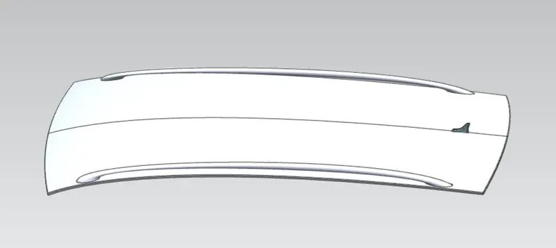
From this styling part we going to first create the bow roof 2. so for that we need the offset of the styling part so we export the required surface as shown in fgure.
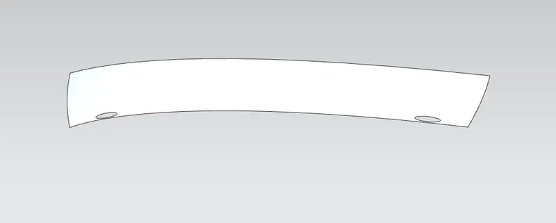
After that untrim the surface for cover the hole created before in the styling part. And for the secound bow roof place this at the distance of 1500mm. so there need to create the plane as shown in figure.
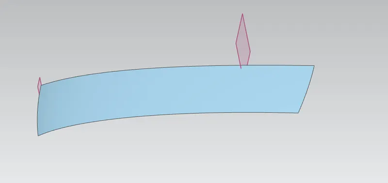
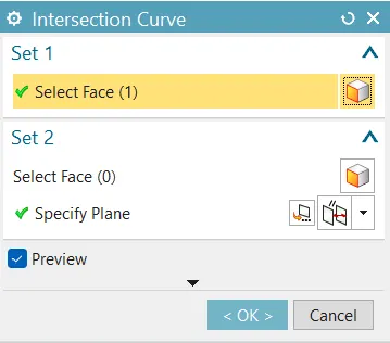
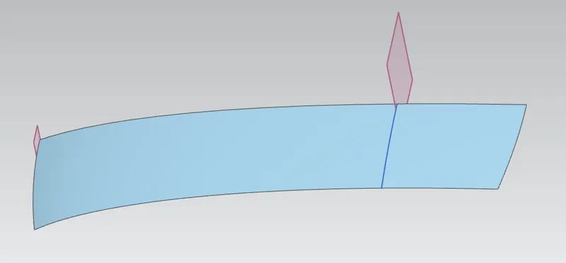
There the bow roof is stright line in the wide direction. so next step is to create the intersection curve in that surface by using the Intersection curve tool as shown in figure.
Then next step is to make the line with the needfull distance for that the given master section we need to create the minimum angle of 7 degree and the overall distance is around 65-75 as given in the bow roof master section as shown in figure.
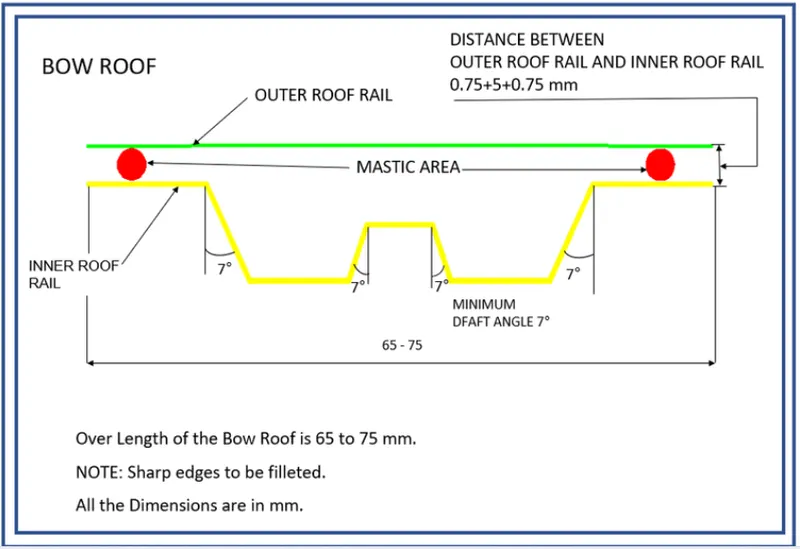
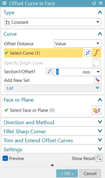
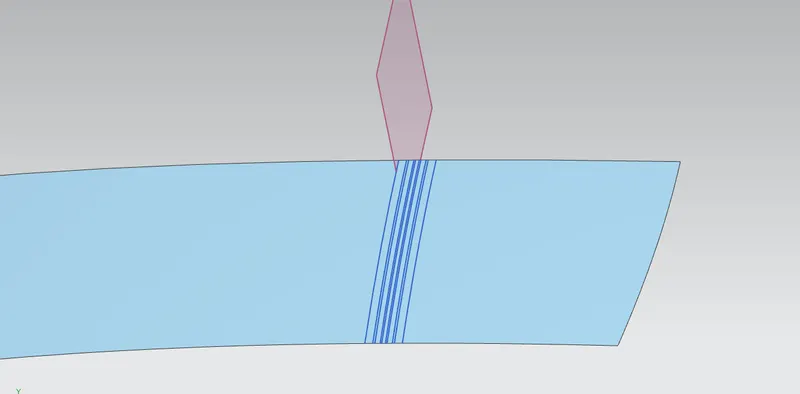
so from the mater section we create the offset the intersection curve for the required distance using the offset curve in face tool as shown in figure.
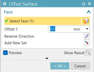
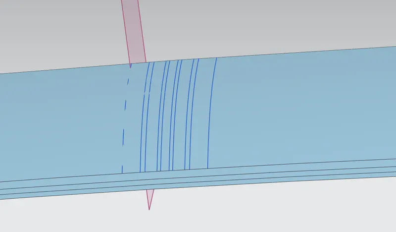
And also create the required offset surfaces from the references of the master section for the distance of first offset is 6.5mm and the secound is 11mm and the thired offset surface is 15mm as shown in figure.
So for create the required shape from the master section project the curve for the required plane as shown in figure.
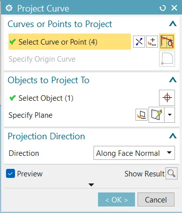
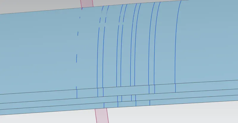
After project the curve for the required surfaces as shown in figure next step is to cut the sheet by using the tool called trimsheet as shown in figure.
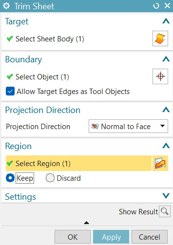
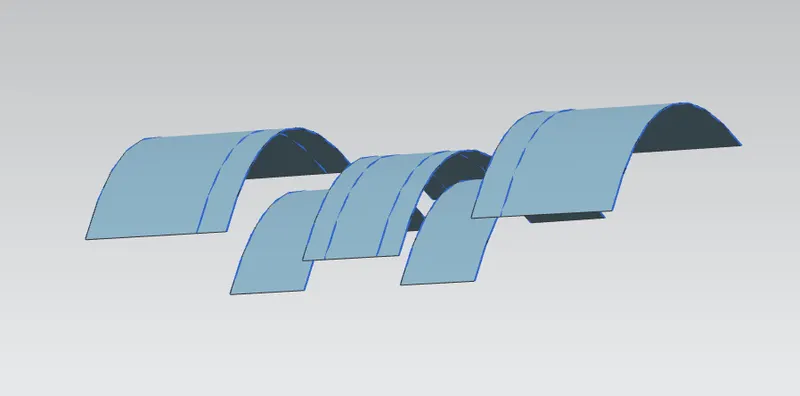
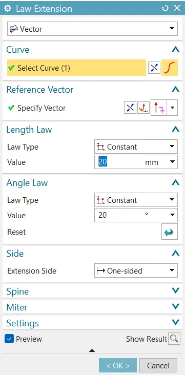
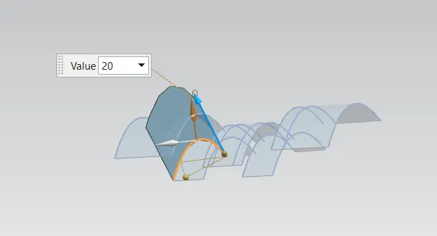
Then need to create the surface in between the two surfaces as given in the mater section it need to be minimum 7degree so for that we use the law extension tool for extend the surface for the required surface at the some angle as shown in figure.
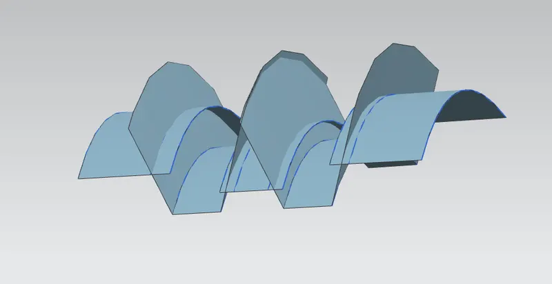
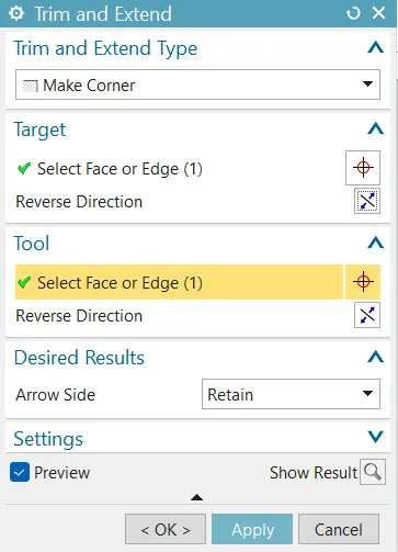
After create the required extension surface need to cut the extra sheet make the corner at the ends by using the trim and extend tool as shown in figure.
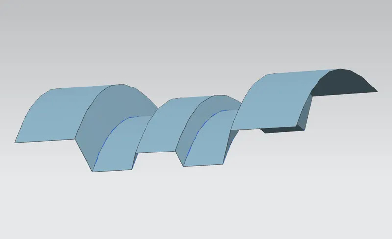
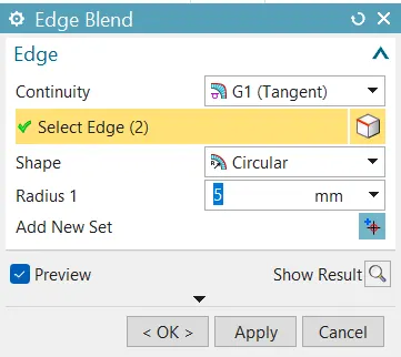
Next step is to create the smooth corners using the edge blend tool as shown in figure.
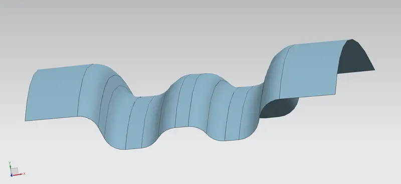
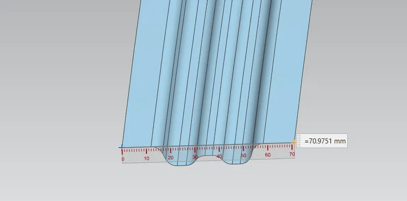
After create this surface we check the overall distance for the given master section 65mm to 75mm. so using the mesuring tool we check the overall distace is 70.97mm is ok as shown in figure.
After this we need the outer edge for join the outer roof with this Bow roof. so offset the outer edge at 6.5mm distance as shown in figure.
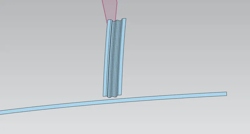
And next is to trim the sheet for the short length when compare to the bow roof as shown in figure.
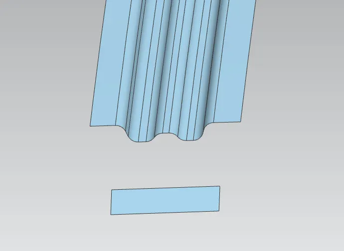
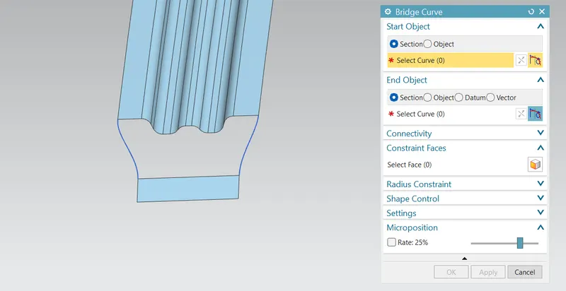
Next step is to join that surface with the bow roof by the smooth transition surface for the we create the smooth curve by using the Bridge curve as shown in figure.
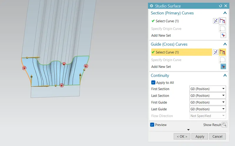
Then to create the smooth surface use the studio surface tool and select the guide curves in that box as shown in figure.
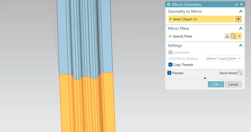
Then next step is to create the other side for the bow roof so for that using the mirror tool create the full bow roof as shown in figure.
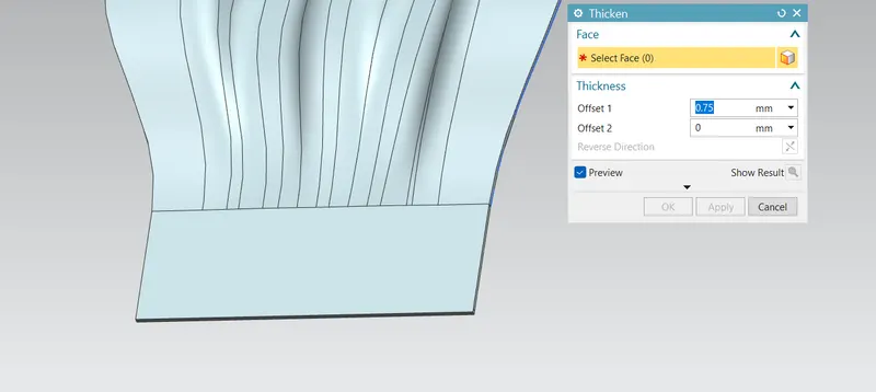
After create this full bow roof we need to give the required thickness using the thicken tool and create the thicken for the above surface as shown in figure.
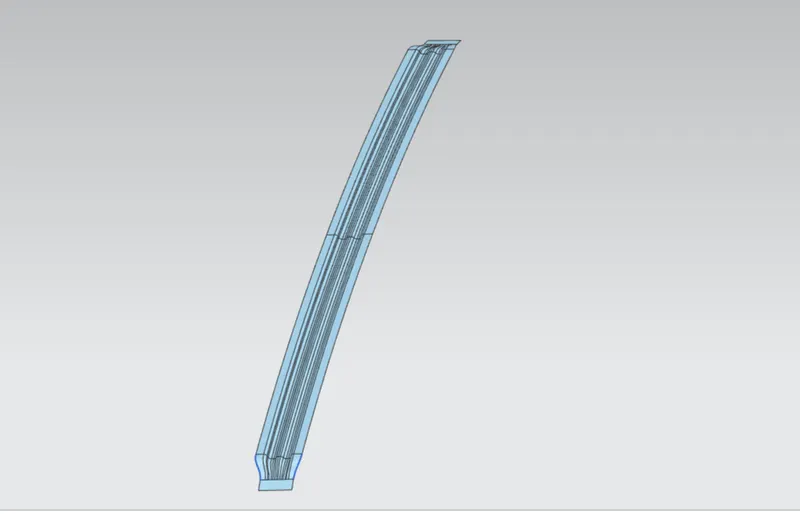
By using the similar procedure for create the other parts like the Bow Roof 1 and Front Roof rail.
Fron Roof Rail :
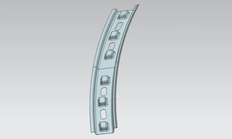
Bow Roof 1 :
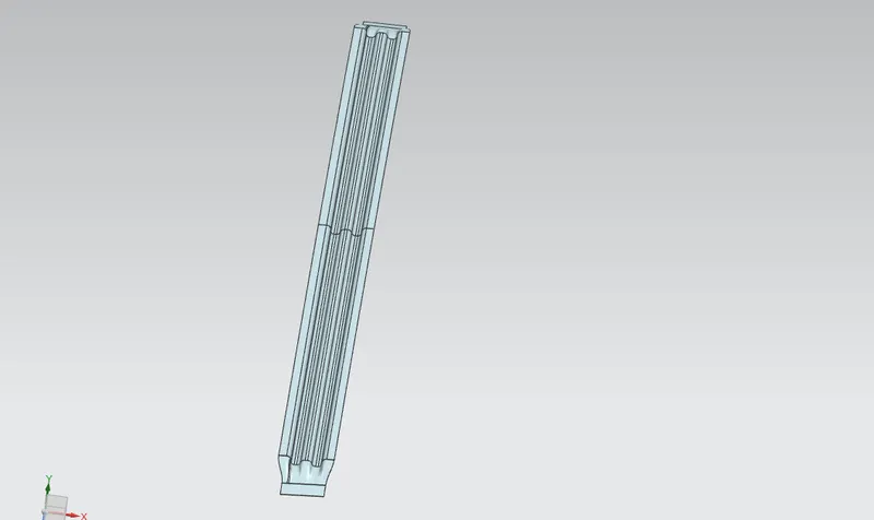
Center Roof :
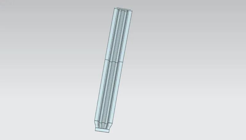
Bow Roof 2 :
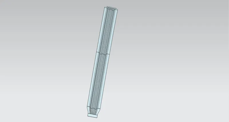
Rear Roof Rail :
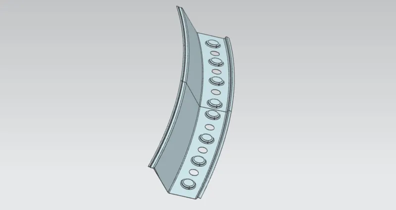
Outer roof :
Assembly view :
Heat Distortion Criteria :
Next we are going to analysis about this heat distorsion criteria for the roof assembly. For that the following is the formula to find the Heat Distortion (W)
Formula - Heat Distortion :
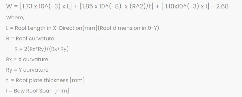
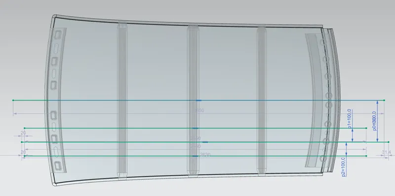
For this we need the Rx and Ry values. for this we draw the line in the Y=0 axis in the roof assembly. and from that line draw another line parallel to this line with the distance of 300mm for the standards and from that line draw another two line parallel to that line in both direction for 100mm each as shown in figure.
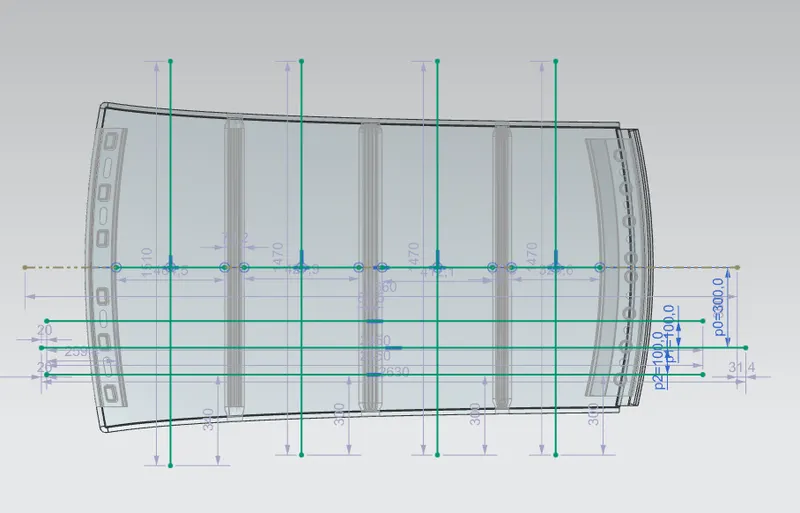
Next step is to draw the line in the X axis for the mid of the each bows as the four line inbetween the bows. And from that line need to draw the parallel of 100mm distance in the two sides as shown in figure.
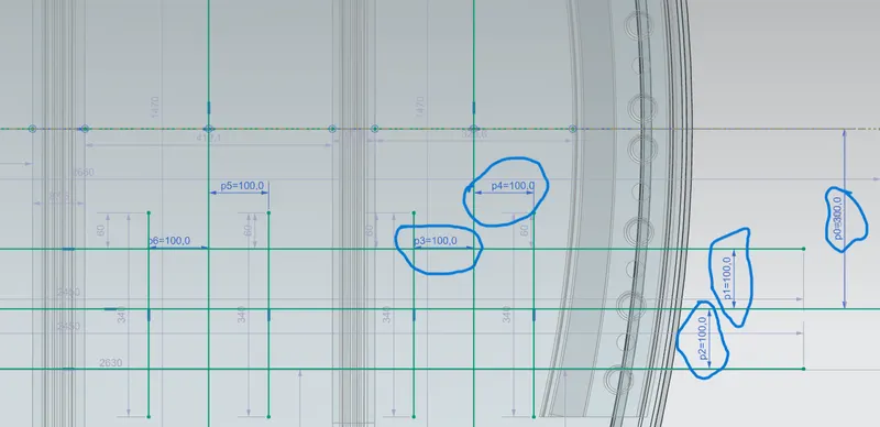
From that line the 100mm lines inter section points of the X axis line and the Yaxis line is the points we need. so draw the points in that intersection places as shown in figure. and delete the other reference lines.
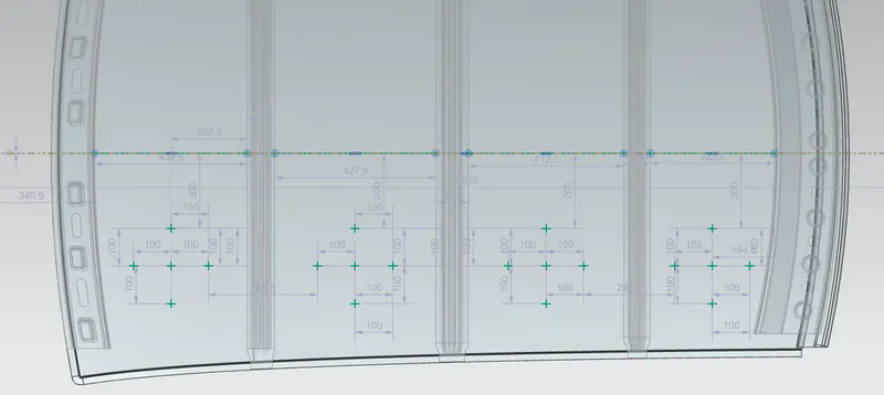
And next step is to project the points in the outer roof. for Rx value we use the three points in the X axis make the circle(Three point circle) with reference of that points and find out the radius of that section is the Rx value. For Ry is the similar procedure but in the Y axix points. After findout the required Rx and Ry points and required parameters tabulate the value for find the heat distortion value. And by using the above for formula we tabulate the results as shown in table given below.
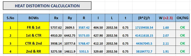
From the results the W value is less than the 2.3. And the value we obtain is also with less than the limit value so the condition is satisfy this roof. Heat distortion is OK for this Roof design.
Snow Load Calculation :
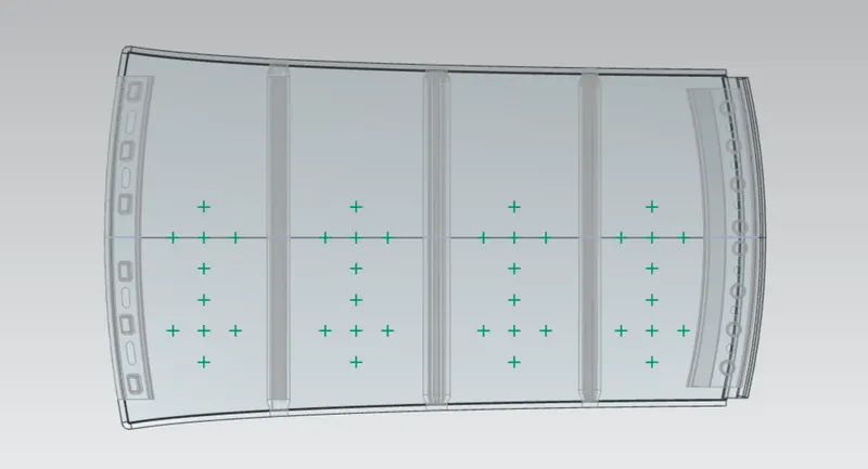
This snow load calculation is also the similar thing this calculation is for load capacity of the roof. For this also we need the Rx and Ry values for this curvature we did the same procedure as done for the Heat distortion but in the Y=O axis it self as shown in figure.
Formula :
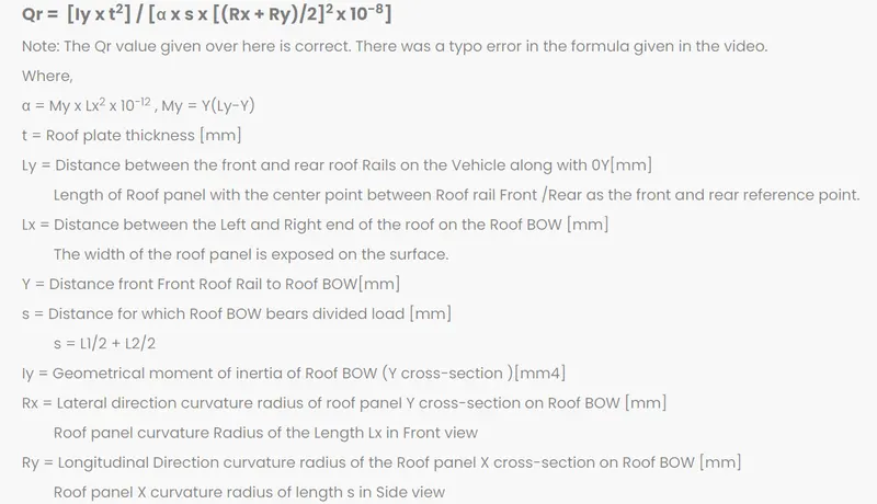
The valuse for the Rx and Ry are the curvature of the point on the roof. and the required Lx and Ly values are tabulated. And the calculations are done using the xl-sheet itself as shown in table given below.
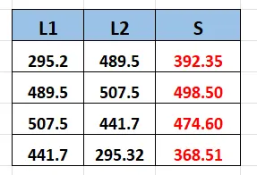
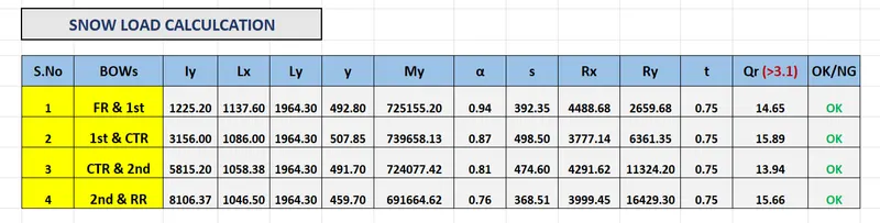
From the table the results the Qr is need to above the 3.1. Here this Qr value is satisfy the condition. So the roof design is pass in this calculation for snow load.
Conclusion :
Hence the design the roof and its reinforcements from the given styling surface received and the design calculation for the heat distortion criteria and snow load calculations are done sucessfully. And this design is pass the two conditions.