MBD Simulation on a Piston Assembly
MBD of Piston Assembly
Aim :
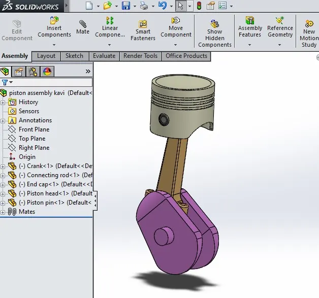
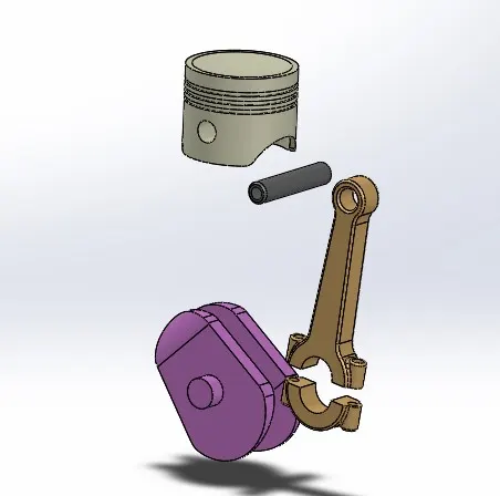
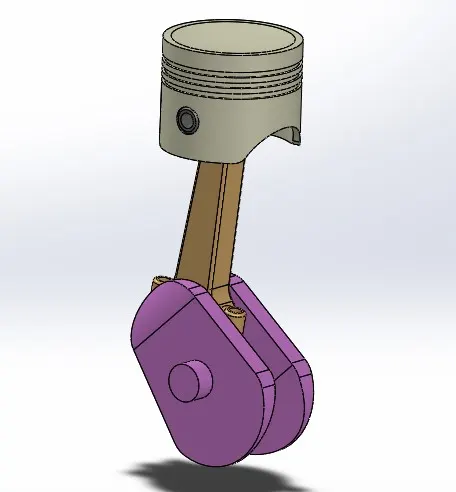
To create all the parts of piston assembly and assemble them in assembly workbench and run the motion analysis using solidworks motion study.
Objective :
- To create all parts of piston assembly and assemble.
- To run motion study analysis for the following cases.
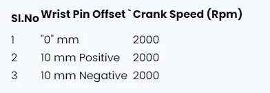
- To plot the linear displacement of the piston head in all three cases and then superimposing graphs by exporting them to microsoft excel.
Theory :
A piston is a component of reciprocating & engines, reciprocating pumps, gas compressors, hydraulic & pneumatic cyliders among other similar mechanism. It is a moving component that is contained by a cylinder and is made gas tight by piston rings. In an engine, its purpose is to transfer force from expanding gas in the cylinder to the crankshaft via the piston rod or connecting rod.
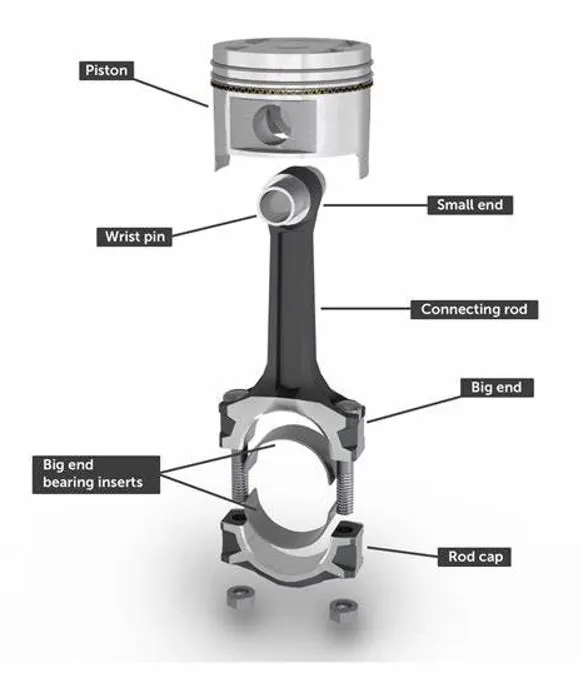
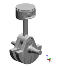
In some engines, the piston act as a valve by covering and uncovering ports in the cylinder. Various application is used piston assembly such as hydraulic cylinder. Various application is used piston assembly such as hydraulic cylinder, shock absorber, fire piston & syringe.
Procedure :
Create all parts :
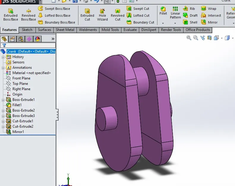
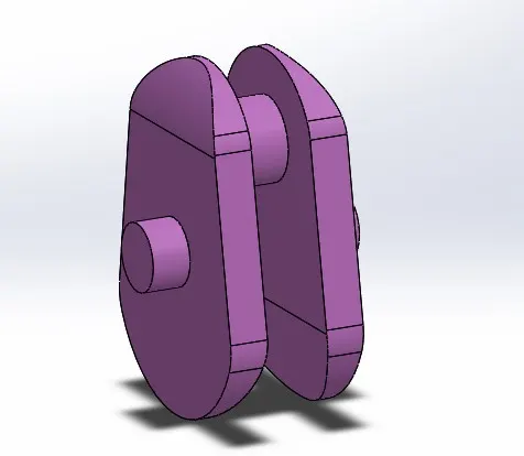
Crank :
A crank is an arm attached at a right angle to a rotating shaft by which circular motion is imparted from the shaft. In a reciprocating engine, it translates reciprocating motion into rotational motion.
Crank is a rotating part of the piston assembly.
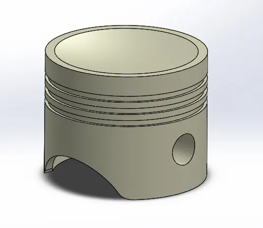
Piston head :
The piston is a moving disk enclosed in a cylinder that is made gas-tight by piston rings. A piston aids in the transformation of heat energy into mechanical eork and vice versa. Piston are a key component of heat engines. Piston are worked by transforming force output by expanding gas cylinder to a crankshaft which provides rotational momentum to flywheel such system is known as "reciprocating engine".
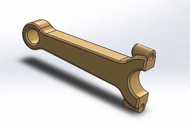
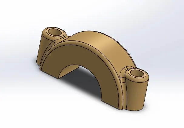
Connecting rod & End cap :
A connecting rod is the part of a piston that end connects the piston to the crankshaft together with the crank. The connecting rod convert the reciprocating motion of the piston into the crankshaft. The connecting rod is required to transmit the compressive and tensile force from the piston. In an internal combustion engine. It allows pivoting on the piston end and rotation on the shaft end. Its most common usage allows internal combustion engine and steam engine.
An end cap is the removable section of a two-piece connecting rod that provides a bearing surface for a crankpin journal.
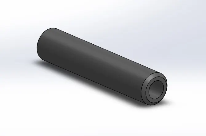
Gudgeon Pin (Wrist Pin)
In an IC engine, the gudgeon pin connects the piston to the connecting rod. Provides bearing for the connecting rod to pivot upon as the piston moves.
Assemble All Parts :
Motion Study Analysis :
The motion syudy : In the motion study the following steps are performed.
- Motor is given to crank with the speed 2000rpm in clockwise direction.
- Frames per second are given as 7200 with precise contact.
- Contact is given between all parts.
- The matrial selected for each case is steel (Dry).
- Gravity in the Y direction (Downward).
For the following conditons
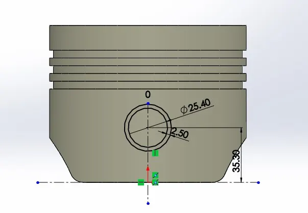
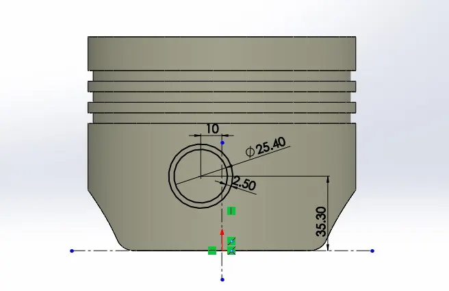
0 mm Offset 10 mm Positive Offset
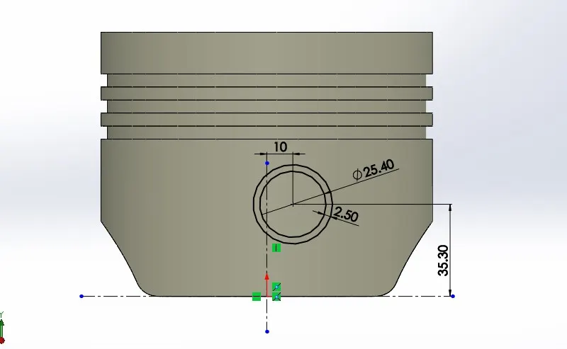
10 mm Negative Offset
Linear Displacement setting :
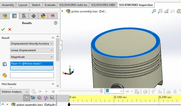
Case 1: Linear Displacement at "0 mm" Offset
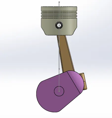
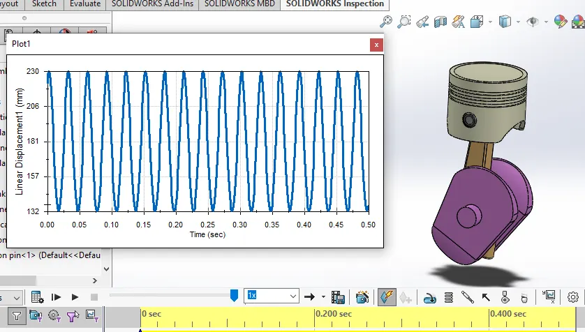
Linear Displacement "0" offset
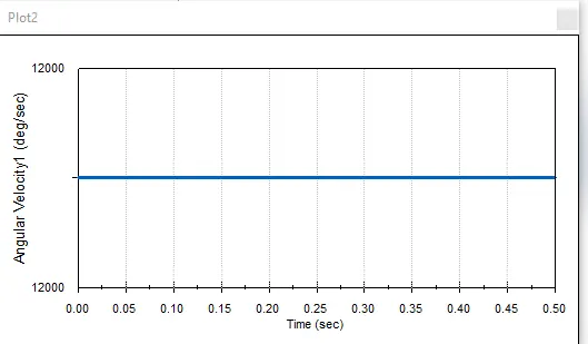
Angular velocity plot
In this plot x axis is Time in seconds and y axis is Linear displacement of the piston head which is move from TDC to BDC. In this plot BDC at around 132mm to TDC 230mm. So the range is 98mm. So the piston is move 98mm linearly. This is happen in the regularly and create same wave patterns.
Case 2: Linear Displacement at "10 mm" Positive Offset
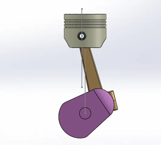
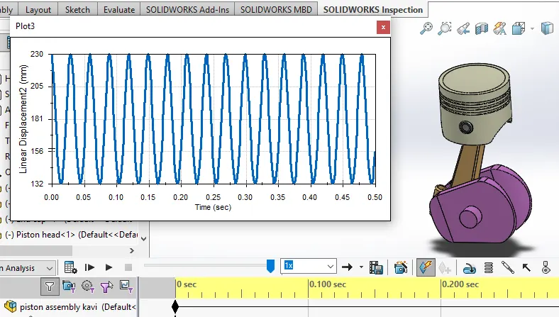
In this plot x axis is Time in seconds and y axis is Linear displacement of the piston head which is move from TDC to BDC. In this plot BDC at around 132mm to TDC 230mm. So the range is 98mm. So the piston is move 98mm linearly. This is happen in the regularly and create same wave patterns.
Case 3: Linear Displacement at "10 mm" Negative Offset
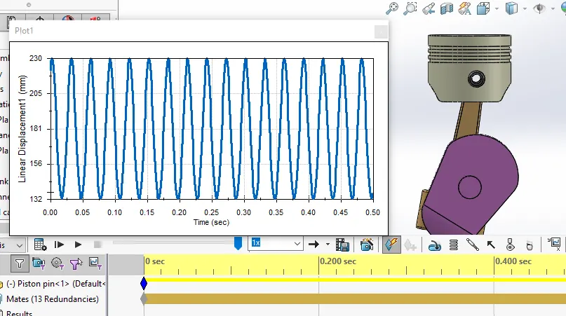
In this plot x axis is Time in seconds and y axis is Linear displacement of the piston head which is move from TDC to BDC. In this plot BDC at around 132mm to TDC 230mm. So the range is 98mm. So the piston is move 98mm linearly. This is happen in the regularly and create same wave patterns.
Export all results to Excel sheet:
After plot all three plots next step is to export this data to excel sheet. And then compare all the results.
Observation :
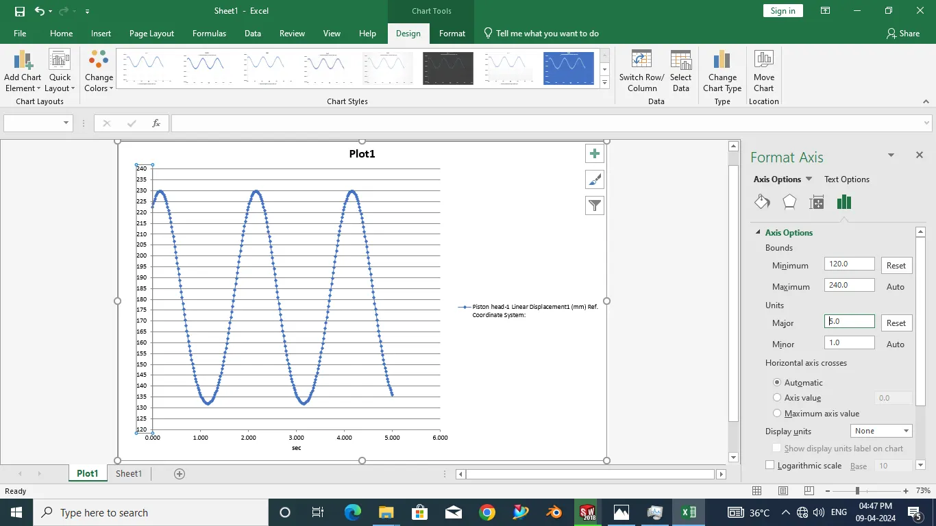
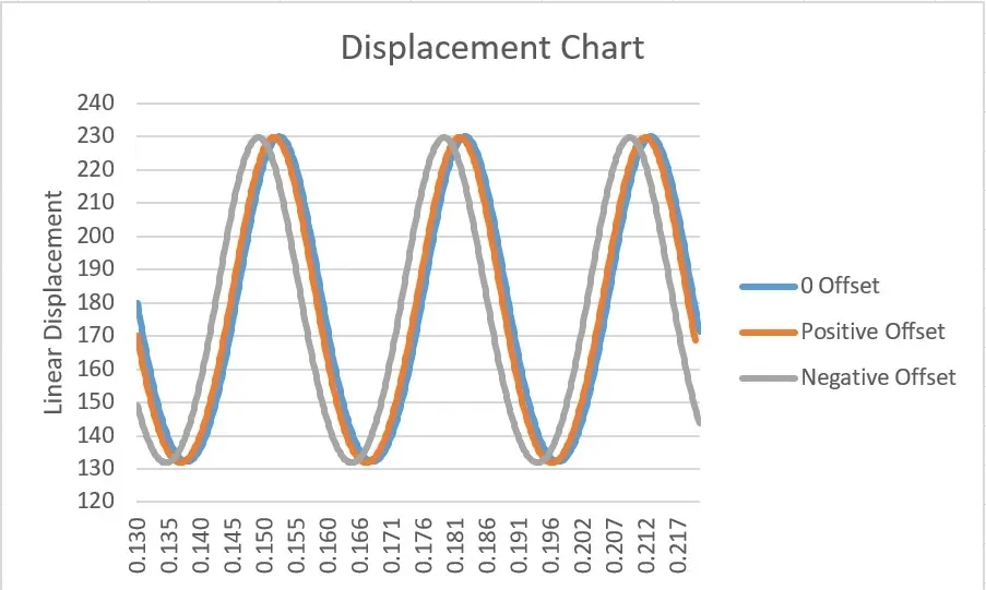
After exporting the requred datas then we need to create the area chart using the MS Excel sheet feature. By this chart we can see clearly the results as shown in figure. In the plot three waves are present according the the three different cases we plot. With this we can see the BDC and the TDC are at 132mm and 230mm respectively at the same pattern. In the plot the third case Negative offset wave is touch the TDC at some time Earlierly.
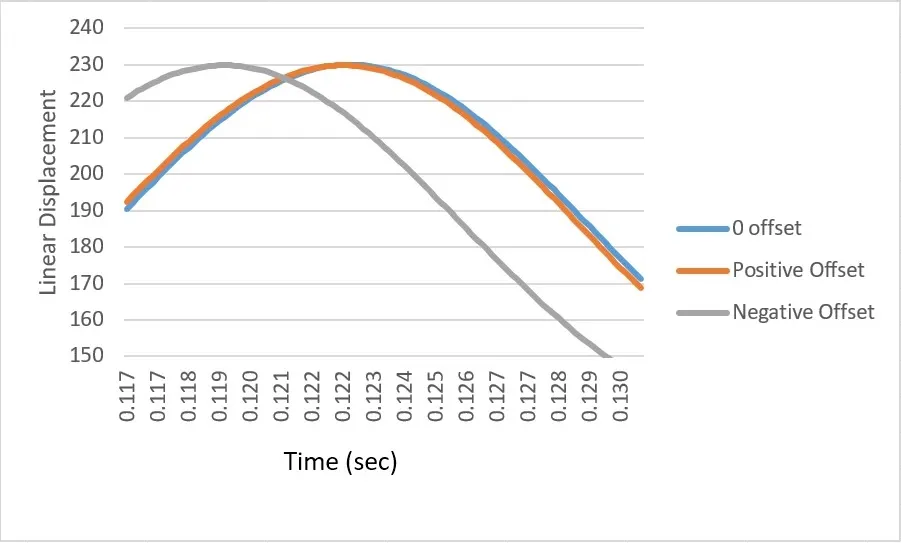
And further zoom into it we can see in this plot the case 3 Negative offset the piston head is touch the TDC earlierly when compared to other two cases. Otherwise the piston moving distance is same in all three cases.
About Sliding Resistance :
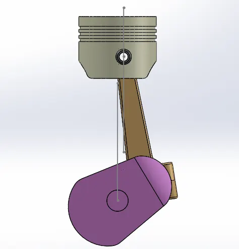
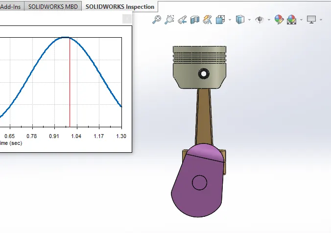
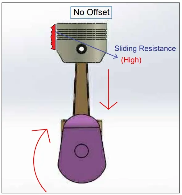
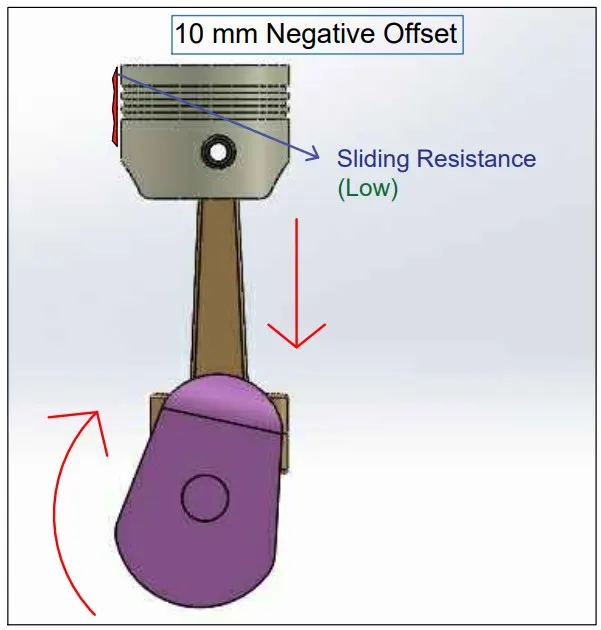
Now we consider the resistance for this three cases. For the we need the TDC position of all three cases as shown in figure.
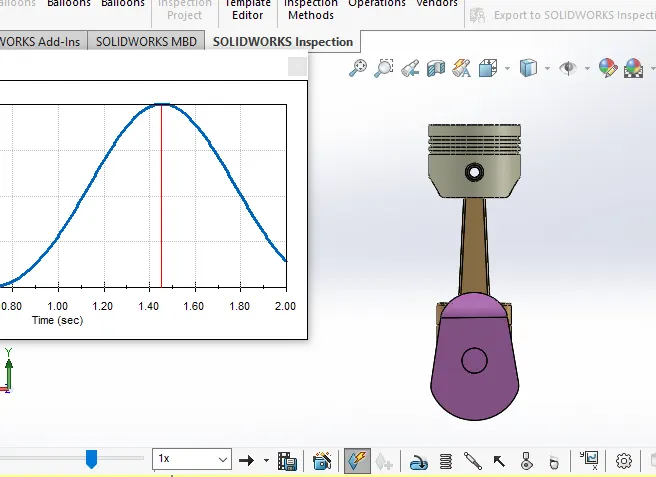
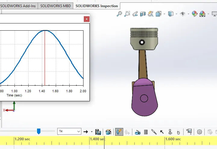
0 Offset 10mm Positive offset
10mm Negative offset
Result :
In the position of all three piston assembly the 0 offset the connecting rod is straight to the piston head. In the third case 10mm negative offset the connecting rod is slightly bend to make the next rotation. By this the sliding resistance of the piston head to the cylider wall is very low. And the case 1 the sliding resistance of the piston head to the cylider wall is very high. By this small difference make the engine more speed and more efficient one.
Attached Files :
1) Part and Assembly file
2) Animation Video