Week 8-3D Tetra Meshing Challenge
Tetramesh generation on components using various available techniques
1. Hosing model
It was a model of housing as shown in the attached figure.
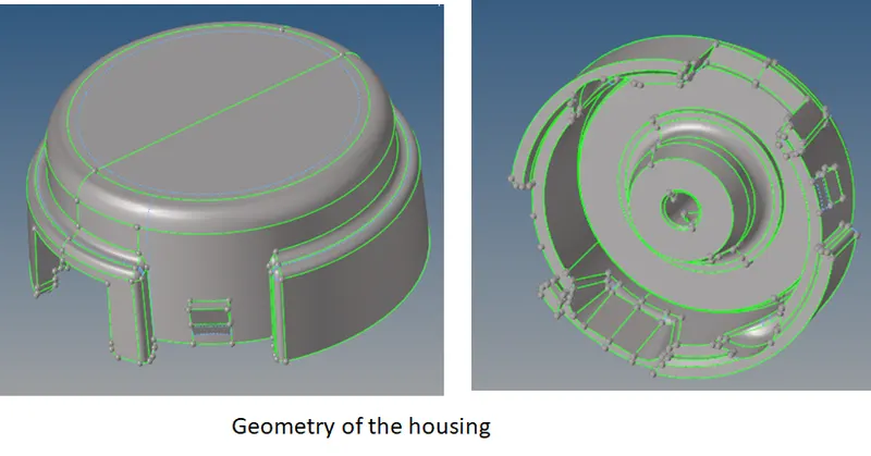
Fig 1.1: The housing model imported in the Hypermesh
The method used to get the 3D tetra mesh on this component was the conversion of 2D tria mesh into tetra mesh. The minimum element size was 2mm, the target size was 5 mm and the max size was 7 mm for the tria elements. The value of tet collapse was kept at 0.15 for the 3D elements. Geometry cleanup was performed on the model to avoid the element failures for minimum length.
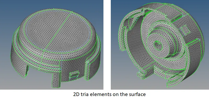
Fig 1.2: The 2D mesh generated on the surface using the tria elements only.
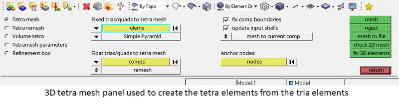
Fig 1.3: The tetra mesh panel used for generating the 3 D mesh.
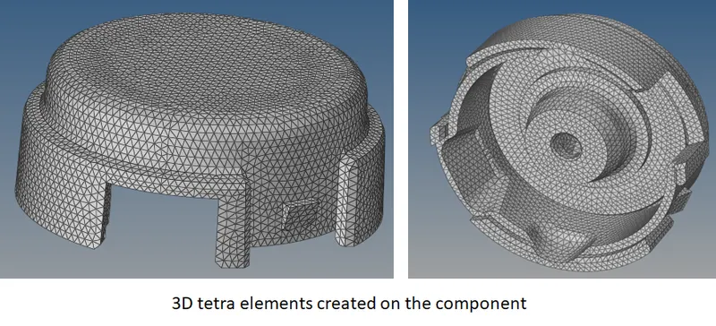
Fig 1.4: The 3D tetra mesh generated on the component.
This method resulted in a total of 77097 tetra elements made of 17672 nodes with a minimum tet collapse value of 0.1505.
2. Model 2:
This was again a model of housing from some machine component. The geometry was loaded into the Hypermesh as shown in the attached figure.
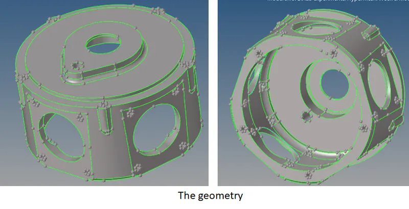
Fig 2.1: The housing model used for meshing.
The method used for this model was the quick tetra option available in the utility menu under the geometry mesh.
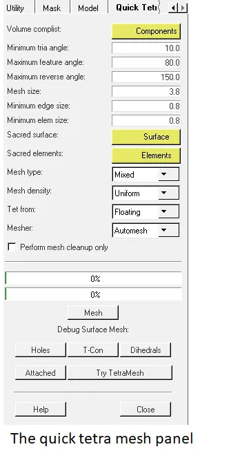
Fig 2.2: The quick tetra mesh panel.
The quality criteria for this model was target element size: 3 Units and minimum tet Collapse: 0.15. The use of quick tetra mesh creates 2D mesh in the same collector in which geometry is located and 3D elements are created in a separate collector named "quick tets". This method of mesh generation does not require much geometry clean up as it is performed automatically before meshing.
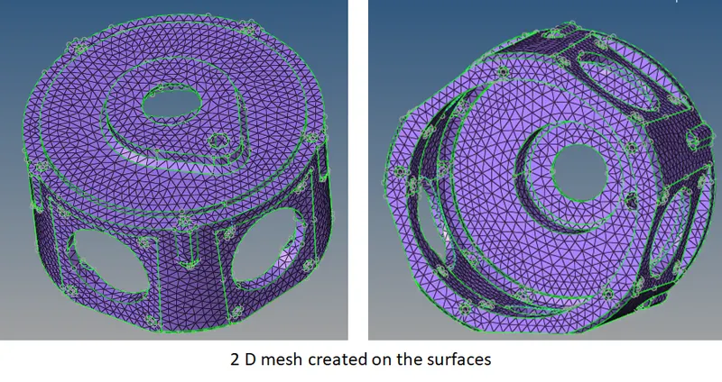
Fig 2.3: the 2d mesh generated on the surfaces.
This resulted in 5601 nodes making a total of 11306 tria elements.
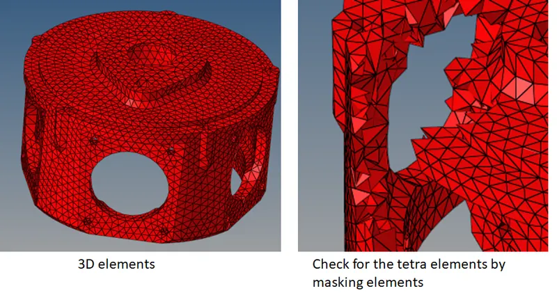
Fig 2.4: The 3D elements created on the component.
A total of 10476 nodes making 66283 elements. Initially, elements were failing for tet collapse which was corrected using the tetra remesh panel.
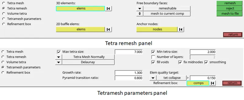
Fig 2.5: The tetra remesh and parameters panels
The tet collapse correction was performed by selecting the generated 3D elements and 2D elements of the mesh under 3D elems and 2D baffle elems respectively in the tetra remesh panel. In the parameters panel values were entered as shown in the above fig 2.5. This eliminated most of the failures and the remaining elements were cleaned using the translate node option. Finally, the minimum tet collapse was 0.1525 meeting the criteria.
3. Turbocharger model
This was the last model meshed under this exercise. It contained a total of four components as shown in the attached figure.
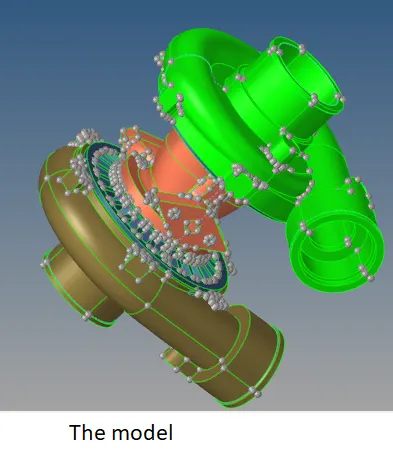
Fig 3.1: The imported turbocharger model
Meshing was done component-wise using the quick tetra panel. The quality criteria for this model was target element size: 4 Units and minimum tet Collapse: 0.15. Steps were same as those used for the previous component. The attached images show the mesh generated on the component.

Fig 3.2: the tetra mesh on the components
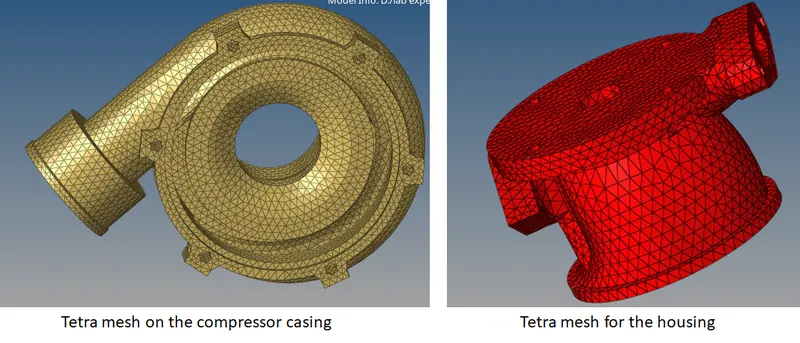
Fig 3.3: the tetra mesh generated for the remaining two components.
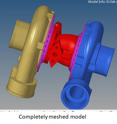
Fig 3.4: The meshed model.
In this way, a total of 35190 nodes making 149212 elements were created and the tet collapse was at 0.1502.
Models are attached for evaluation.
Thank you.