Week 9-Creation of 1D Connectors Challenge
Creation of 1D Connectors in the Frame Assembly Model in Hypermesh
1. Introduction:
In this exercise, a frame assembly was meshed and all the components were joined together using suitable connectors. The model contained a total of 9 components as shown in the below-attached figure.
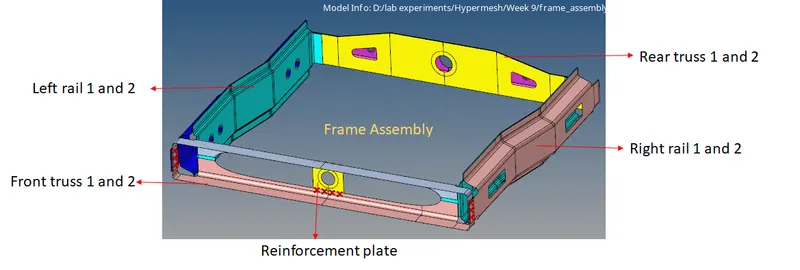
Fig 1.1: The Assembly model
All the imported components were put into separate collectors for the sake of convenience while assigning materials and performing other operations. After that, Geometry cleanup was performed in accordance with the minimum and maximum element sizes allowed. The next section has details of the mesh.
2. Meshing
After clean-up the following quality, criteria was set in the preferences section of the hypermesh.
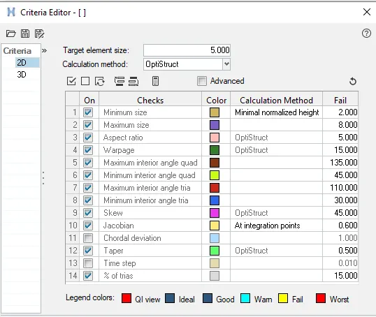
Fig 2.1: Quality criteria for the 2D mesh
Then 2D mesh was created for all the components as shown in the below-attached figures. Element type was set to mixed and a target size of 5 units was chosen for the mesh.
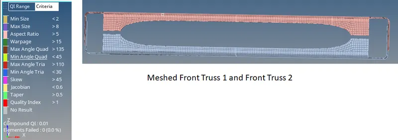
Fig 2.2: Mesh generated on the Front truss components
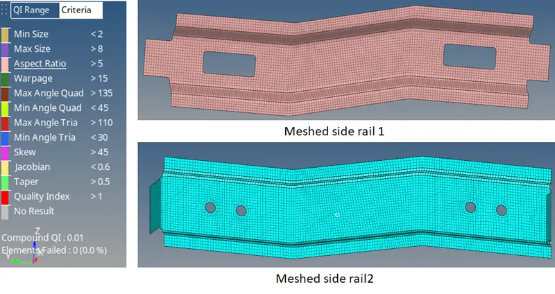
Fig 2.3: Mesh generated for the side rail components
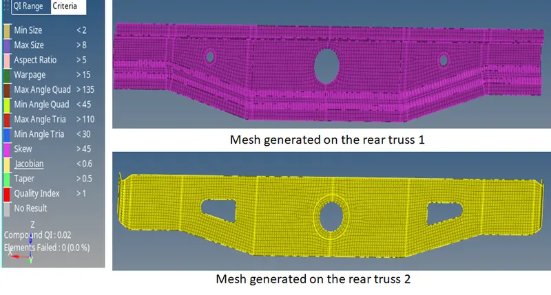
Fig 2.4: Mesh generated on the rear truss components
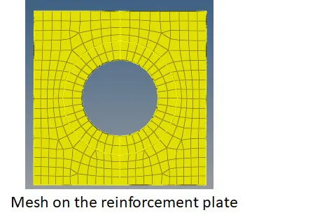
Fig 2.5: Mesh on the reinforcement plate
This approach generated a total of 40056 elements made of 42100 nodes.
The next step was property assignment to all the components specifying thickness (as all the components were surfaces and 2 D mesh was used ). A common material named steel was created for all the components. Then separate properties were created for all nine components. Properties were assigned separately to facilitate easy modification in thickness values for components at a later stage.
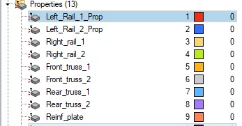
Fig 2.6: The properties created for components.
After that, the connectors were created for joining all the component together as explained in the next section.
3. Modelling of connectors
Connectors are used to join two entities together or in other words, they are used to represent the CAD geometric connections for FEA. Some of the connectors used widely are Spot weld, Seam weld, Bolts and adhesives.
Following connections were mentioned as part of the guidelines for the exercise and the rest of the connections were decided based on the location of the connection.
1. Right_Rail_2 & Front_truss_1:- Seam-Quad(angled+capped+L)
2. Left_Rail_2 & Front_truss_1:- Quad elements
3. Front_truss_2, Front_truss_1 & Right_Rail_1:- Spot weld with 2 Layers and 5 mm Diameter
4. Front_truss_2, Front_truss_1 & Left_Rail_1:- Hexa (Adhesive)
5. Rear_truss_2 & Right_Rail_2:- Bolt Connector
6. Rear_truss_2 & Left_Rail_2:- Bolt Connector
7. Right_Rail_1 & Right_Rail_2:- Spot-weld with Rigid Elements
8. Left_Rail_1 & Left_Rail_2:- Spot-weld with Spring Elements
9. Rest all the component left Join them with suitable connectors
Based on the above-mentioned connections, the joining process was started with Right Rail 2 and Front truss 1 components. A seam weld with capped quad elements was created as shown in the below-attached figure:
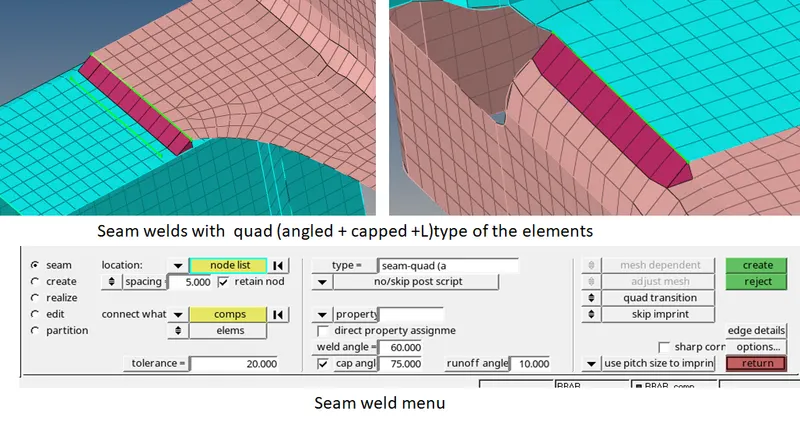
Fig 3.1: Modelling of the seam weld connector for the Right Rail2 and Front truss 1 components.
For the connector to get realised properly the following parameters need to be taken care of:
| 1. Spacing | It should be approximately the target element size, here it was kept 5 mm |
| 2. Tolerance | It is the search radius for which nodes from the other component will be looked for connection, It should be equal to the gap between the components |
| 3. Weld angle | The general value for the weld angle is between 45 degrees to 60 degrees, Here it was kept at 60 degree |
| 4. Cap Angle | The angle at which caps at the ends are inclined with respect to the adjacent slant element, it was kept at 75 degrees which is recommended for a 60-degree weld angle |
| 5. Runoff angle | In practical terms, it is the angle between the normals of the first slant element and the adjacent weld elements. Its recommended value is between 0 to 10 degrees. |
Mesh dependent mode with quad transition and imprint options were selected for realising the connector properly.
The next connection was modelled between Left Rail 2 and Front truss 1. Again seam weld elements were used but with quad elements as shown in the attached figure.
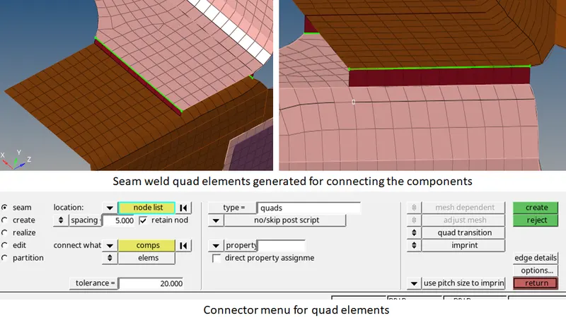
Fig 3.2: Modelling of the seam weld with quad elements
Most of the parameters have already been explained in the previous connector description.
The next connector modelled was to join three components together namely Front truss 2, Front truss 1 and the Right rail 1. Spot weld with acm (shell gap+coating) type of element was used with 5 mm diameter as shown in the below-attached figure.
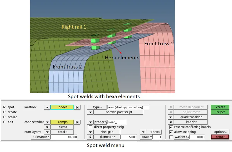
Fig 3.3: the spot weld with hex elements
Spot weld creates node to node connectivity with selected element type. The ACM type creates one hexa element for one set of two nodes that are to be connected together. Washer was not used and the number of coats was kept at 1 for simplicity. The number of layers basically defines how many surfaces are to be connected together. In this case since three components needed to be joined so it was kept to 3.
Next, hexa adhesive elements were created for connecting Front truss 2, Front truss 1 and the Left rail 1. Seam weld with element type set to Hexa adhesive was used as shown in the attached figure. Since the Hexa adhesive does not allow more than two components, a set of two connectors as shown in the attached figure was used.
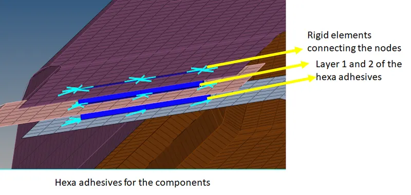
Fig 3.4: The hexa adhesives used to connect the three components together
After that, some bolt connections were modelled to connect the rear truss 2 with left and right rail number 2 as shown in the attached figure.
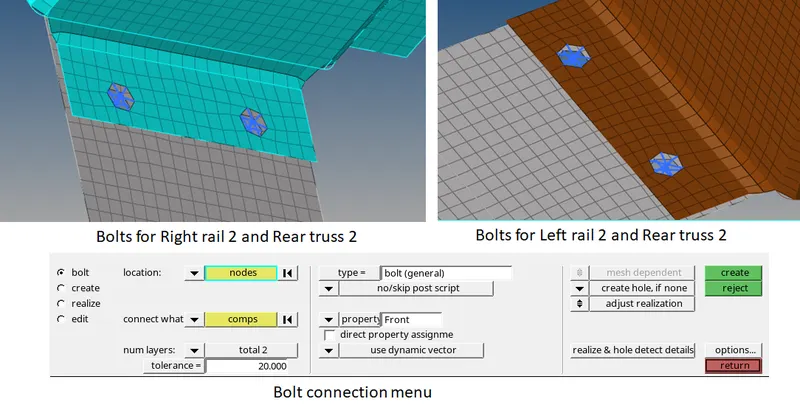
Fig 3.5: Bolt connections created for the components
Adjust realization option is chosen because it enables the connector to get realized in the cases of mating nodes not being aligned properly. The elements created were all RBE2 elements in the connector.
The next joints created were for the edges of the rail components. They were joined together with spot weld connections as shown in the attached figures.
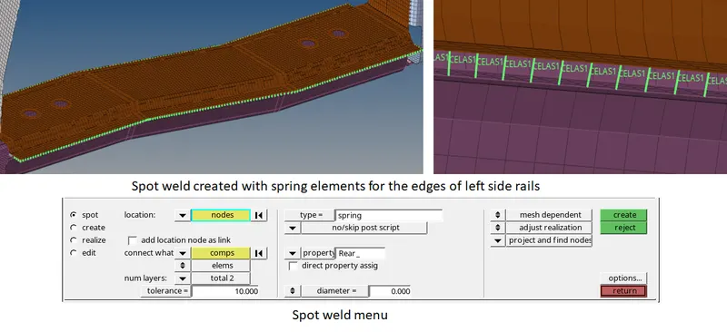
Fig 3.6: the spot weld for joining left side rails together
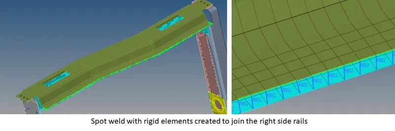
Fig 3.7: the spot weld for joining right side rails together
Then the Rear Truss components were joined together using a bolt connection. The size of the available hole was measured first using the three nodes option, it was 50 mm. Then RBE3 element spiders were created for the two holes as shown in the below figure. After that, a beam element with a beam section to match the size of an M48 bolt was created as shown in the attached figure, joining the independent nodes of the clusters.
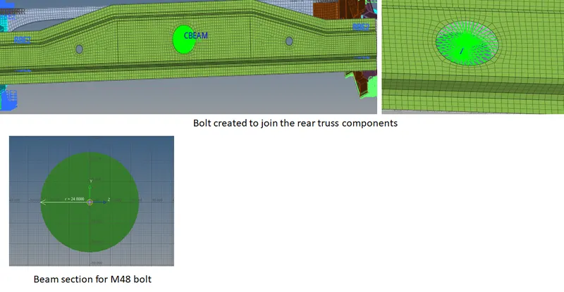
Fig 3.8: The M48 bolt created to join the rear truss components.
Since a bolted joint was made between the rear truss components their edges were not joined together with connectors like spot weld or adhesive.
At last proper material were assigned to all the connector elements and also segregation was done followed by deleting the empty collectors.
Please find the attached hypermesh model :Frame Assembly Model
Thank you.