Week - 3 Drop test Challenge
Drop Test of a mobile phone in LS-DYNA
In this exercise, a file having just nodes and elements of two parts, a simplified cellphone and a plate mimicking ground was provided and it was asked to create a complete simulation file from it. Then a drop test needed to be performed. *INITIAL_VELOCITY card needs to be used to give velocity specifications for the cellphone.
As we focus only on the time when impact happens, we ignore the orientation of the phone and the way it travels to the ground. Therefore, the parts were kept close and provided an appropriate magnitude of velocity.
The objective of this exercise was not to get a correct simulation but to get a feel of creating an input deck from scratch.
The given keyword file was opened in the LS-pre post and it was examined properly.
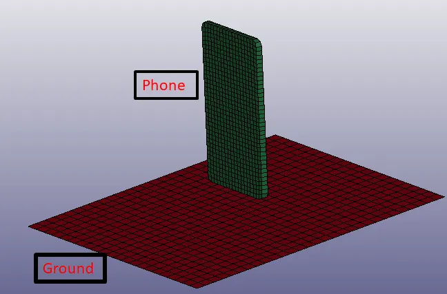
Fig: The provided mesh file.
It contained three parts initially, a solid body with Hexa mesh mimicking phone, a surface body with shell mesh mimicking the ground and a solid body which was also representing the ground. The ground can be sufficiently represented as a surface with shell mesh, so the solid body representing the ground was deleted.
Material and section properties
The first step was to assign material to the parts. Mat24 material card which is a piecewise linear plasticity model was used to assign the values as shown in the below-given image. The unit system used for the model was `[g-mm-ms]`. This material was assigned to the phone so that it could mimic a ductile material.
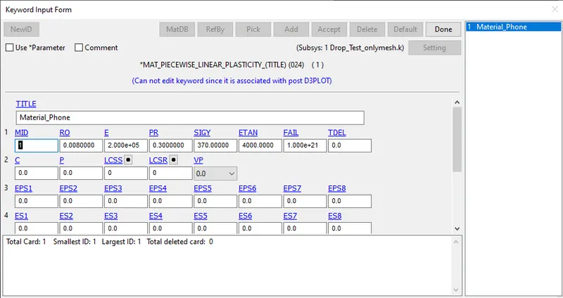
Fig: The mat 024 card used to define phone material.
Then mat 020 card was used to define a rigid material for the ground. When this card is used to assign material to a part, the part starts behaving as a rigid body. Then CMO (Centre of mass constraint option) was set to 1 and con1 and con2 both were set to 7 meaning their DOFs are constrained. This saves us from applying SPC boundary conditions for the ground plate.
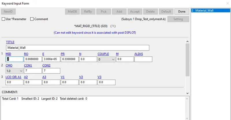
Fig: Mat 020 card used for defining rigid material.
Then section properties were defined for shell and solid elements as shown in the attached figure. A shell card was used to define a thickness of 6 mm and an element formulation of 2. Similarly, a solid card was used to define section properties for solid elements with element formulation set to 2.
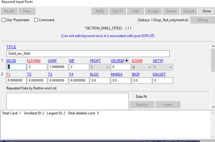
Fig: Shell section card used to define section properties for shell elements.
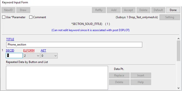
Fig: solid section card used to define section properties for solid elements.
Then these material and section cards were assigned to the parts properly.
Boundary conditions
As a starting point, we need to define that the ground is fixed and the phone is dropping towards it with a certain velocity. The ground can be made fixed by defining a Specific constraint or SPC constraint restricting all the DOFs of edge nodes. But, the material card used for the ground is mat 020 which when assigned to a part, makes it rigid and fixed unless a motion is not defined for it.
The next condition was met using the *initial velocity keyword which was assigned to the phone elements with a velocity of 5 mm/ms in the negative Z-direction as shown in the attached figure.
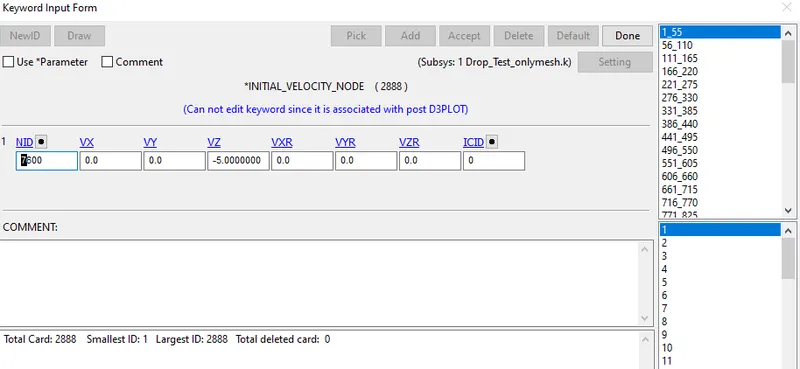
Fig: Initial velocity card used for defining velocity for the phone.
Contact
There will be contact between the phone and the ground during impact. We need to define the type of contact that is needed here. It basically helps us to model the intended behaviour of entities in contact. An Automatic surface to surface contact card was used as shown in the attached figure.
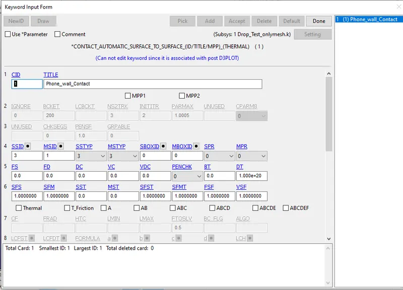
Fig: The automatic surface to surface contact card used for modelling the contact between the bodies during impact
In this contact type, we need to define master and slave entities. The master is one which is stiffer and the relatively softer material is set as slave. Also, the decision can be made according to the item on which we are focusing for deformations. In the card, SSTYPE and MSTYPE were set to 3 which enables us to define master and slave bodies using part IDs. The phone was set as slave and the ground was made as master by assigning SSID=3 and MSID=1.
Control
A control termination card needs to be used to define the simulation time for the setup. An ENDTIME value of 5 ms was used to define the simulation time.
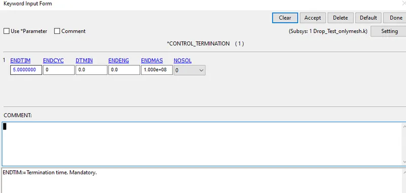
Fig: Control termination card used to define simulation time for the setup.
Output requests
In LS_Dyna we need to define the output files before running the simulation so that we can see them in post-processing otherwise, the quantities will not be calculated. the Database keyword is used to request output files. D3 plot card was used to request the stress-strain and other binary outputs. The ASCII card was used to request
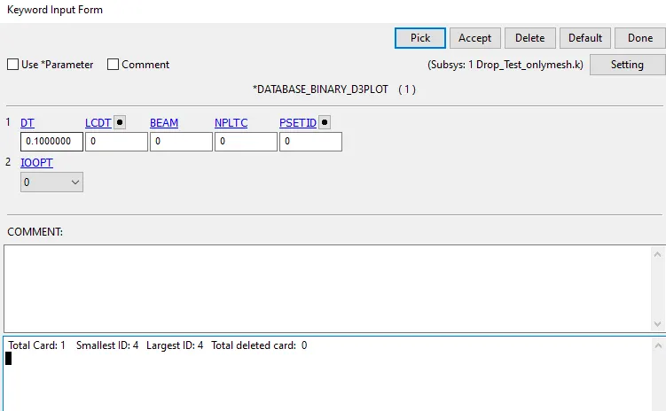
Fig: D3 plot card used to request outcomes at intervals of 0.1ms.
ASCII card was used to request GLSTAT (Energies), Matsum (material energies) and SLEOUT (Sliding interface energies) at an interval of 0.1ms.
Model check and simulation
After completing the file up to this step the keywords were checked using the model check option.
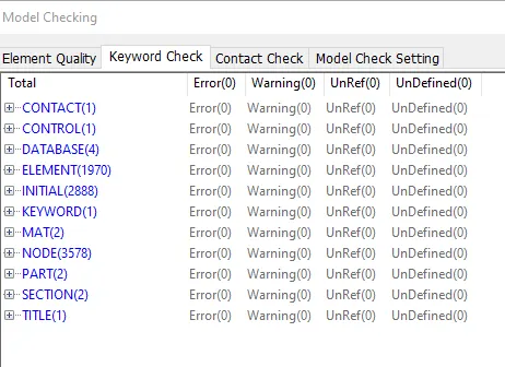
Fig: Keyword check results.
As clear from the above figure there was no error or warning in the keywords, the simulation was run.
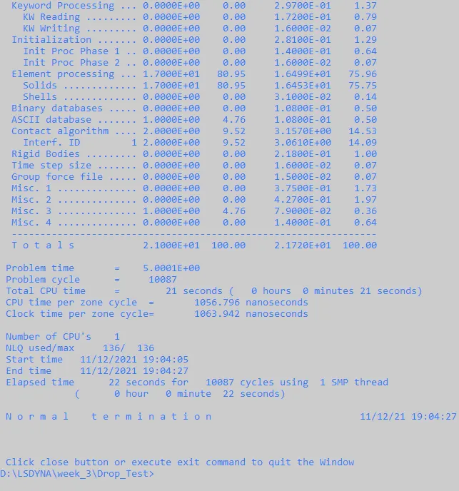
Fig: the run window showing details of the simulation
The normal termination at the bottom shows that the simulation was ok and we can go to post-processing.
Results and Discussion
After running the simulation the plots were opened in the LS-prepost.
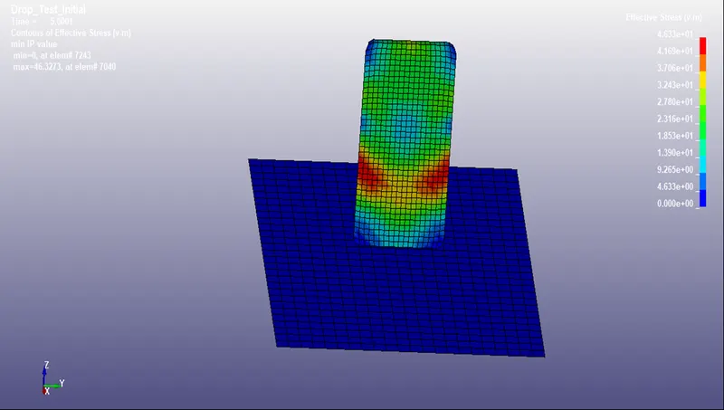
Fig: Stress developed in the phone body at the end of the simulation time.
As clear from the above figure the maximum stress developed in the body was in the range of 46.3 MPa.
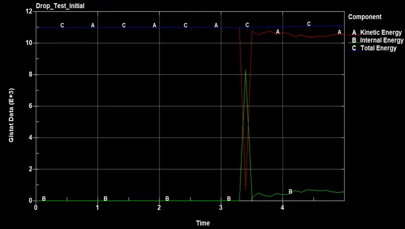
Fig: The plot of Energies
As clear from the above figure, the total energy remains constant.
Next, we need to check for sliding energy to be able to identify any issues with the contacts. The frictional energy should be negligible in comparison to other energies.
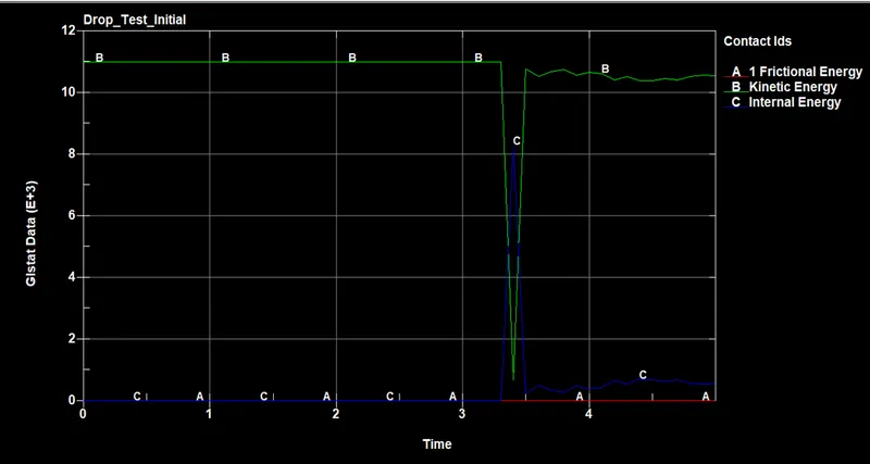
Fig: A comparison of the frictional energy with the total energy of the system.
Clearly, the frictional energy was negligible in comparison to others, so our simulation was good to serve the purpose of this exercise.
Thank you.