Project 1 - 2D meshing on the instrumental Panel
2D Meshing on Instrument Panel of a Passenger Vehicle
1. Introduction
An Automobile body is made of almost 300 parts that are joined together using various techniques. The primary structure for any vehicle is the BIW or body in white. It basically includes all the sheet metal components and frames. In a generic way, it can be referred to as the body which contains all metal components before going for painting. All the other components like engine, chassis, exterior and interior trim etc are mounted on it to complete the vehicle. 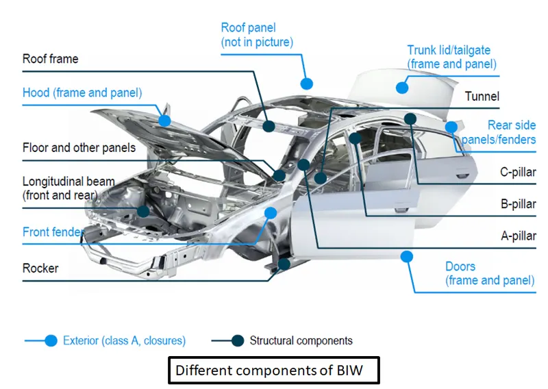
Fig 1.1: The BIW of a Passenger Vehicle
In the design phase of the vehicle, all the components are modelled using CAD software and then it is analysed using CAE techniques. The first step in CAE is preprocessing which includes geometry cleanup (removal of unnecessary features) and mesh generation on the components. The meshed model is then sent to the solver deck where all the boundary conditions are applied to solve the corresponding governing equations for the case. Then comes Post Processing which basically includes the process of drawing conclusions from the results and implementing them in the form of design modifications.
In this exercise, half a portion of the plastic instrument panel was meshed in ANSA. Plastic components pose a unique challenge to the CAE preprocessing engineer due to their complex topology and surface features that require detailed attention as compared to sheet metal parts. The presence of features with non-uniform thickness and dog houses make it pretty difficult to model mid surface for generating a shell mesh.
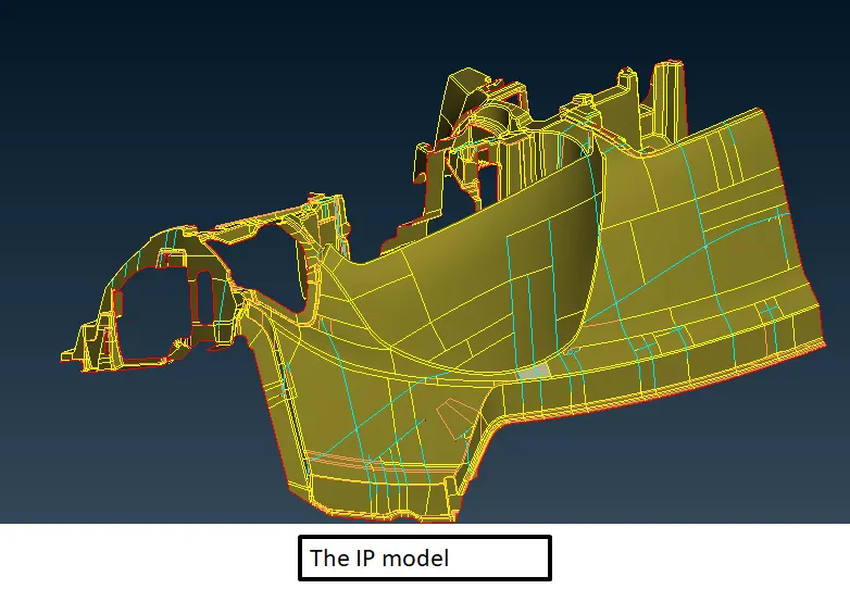
Fig 1.2: The inner panel model
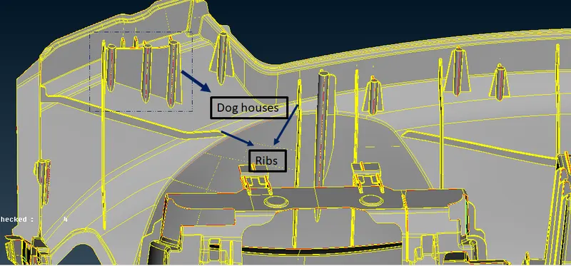
Fig 1.2: the presence of dog houses and ribs in the model.
2. Mid surface and geometry cleanup
This panel has a non-uniform thickness and complex features which are not possible to work directly with auto mid surface generation techniques like Casting and Auto Mid. Casting can be used but it would result in lesser control over element quality. So manual mid surface with the help of the offset method was used to model the mid surface of the model. A major portion of the model was 0.6 mm thick so They were extracted in a single step of 0.3 mm offset in the proper direction. Then all the remaining portions were extracted depending on their thickness values and all the surfaces were attached using various surface modification techniques like extend, intersect, new surface generation and surface modelling with boundary curves.
Capturing the dog houses was pretty difficult as they are hollow from the inside and dint have a defined thickness. They were captured in the form of a cross as shown in the attached figure.
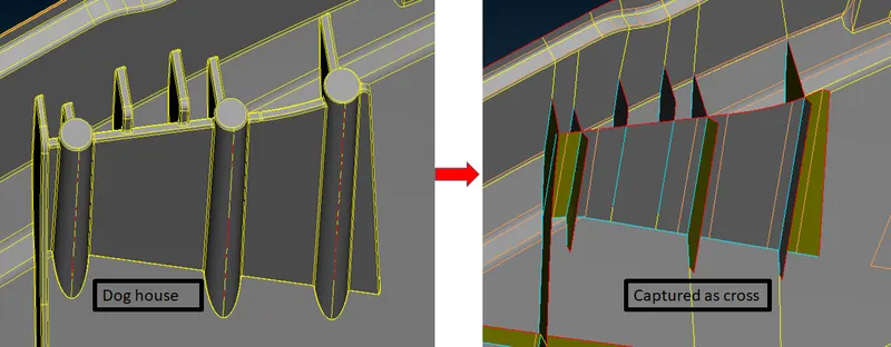
Fig 2.1: the method of capturing dog houses.
This model has a lot of ribs which are reinforcement structures needed to maintain rigidity. They can be captured using a number of methods available in the ANSA. The easiest one is using the mid curve for the rib edges which is then projected to the base surface. Finally, a new surface is created between the curve and projected con which acts as the mid surface for the rib. Another method is to directly offset the surfaces with half the thickness value in the proper direction. Apart from these techniques, the mid command in single mode can be directly used to get the mid surface for ribs.
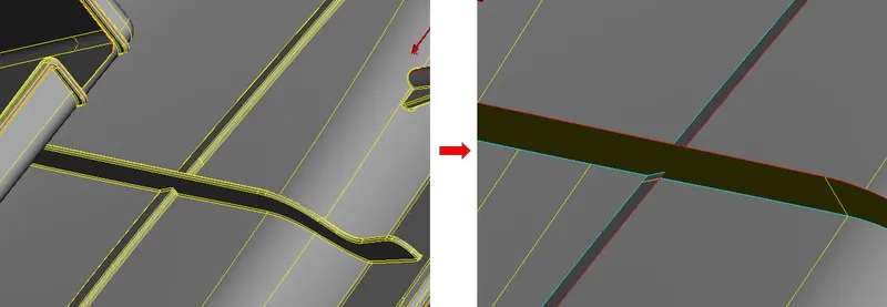
Fig 2.2: The mid surface for ribs
The next step was cleaning up the features to avoid element failures. This needs to be done according to the quality criteria which is required for the model. The attached figure shows the quality criteria followed for this model.
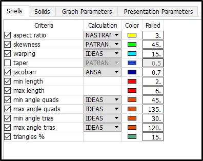
Fig 2.2: The quality criteria followed for the model.
3. Mesh generation
Mesh generation on the mid surface was done with mixed type (quads and trias) with a target size of 4 mm. The method followed was meshing macro by macro to control the mesh flow and element quality. In some of the areas due to geometry constraints, the minimum length failures could not be avoided. Reconstruct command was used to get a better mesh after meshing with the best command. The best command chooses the most suitable method like spot mesh or adv front for the macro and provides initial mesh which can be worked upon for further improvement.
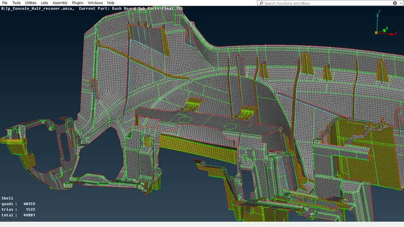
Fig 2.3: The completely meshed model
This approach generated a total of 48359 elements which contains 1522 tria elements.
3. Conclusion
Plastic models require considerable effort for modelling the mid surfaces and mesh generation and the tool knowledge is vital to the successful completion of the task in a timebound manner. Complex features like dog houses can be simplified using approximate surfaces for the purpose of shell meshing and a CAE engineer need to be familiar with such practices. Sometimes it is not possible to completely eliminate or avoid elemental failures and again the user needs to make decisions that should be in accordance with the accepted practices for the case.
The meshed model is attached for evaluation.
Thank you.