Modelling of Predator Yacht in Solidworks
Modelling of Predator Yacht in Solidworks
- Introduction
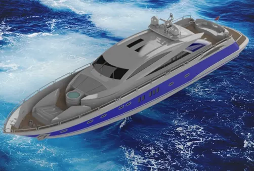
In this project, a cosmetic model of a luxury yacht was built using Solidworks. Most of the technical details were skipped for simplification and a total of nine components were modelled individually and they were assembled.
A blueprint setup was first created with several views scaled properly to reference the parts.
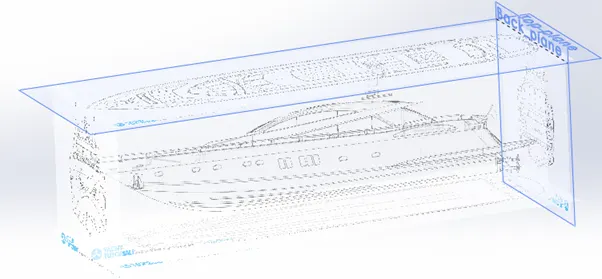
Fig 1.1: The blueprint setup for creating parts.
- The Propeller
After that, the first part to be modelled was the Propeller. It was modelled entirely as a solid component. Mostly used features were extruded boss, revolve and Boundary boss which was used to create the fins. After modelling a single fin, a circular pattern was used to get a total of six fins as shown in the attached figure.
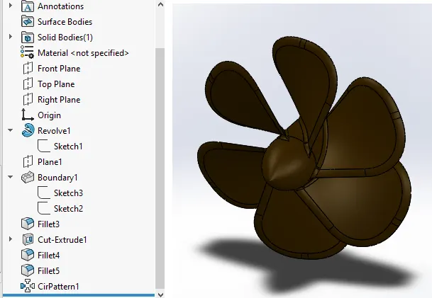
Fig 2.1: the propeller and its feature tree
A total of three propellers were required for the model so during assembly it was called three times.
- The Hull
It was the next part to be modelled after the propeller. The presence of complex features and larger size were the main challenges for modelling it.
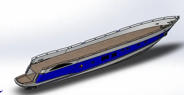
Fig 3.1: The Hull model
The part has symmetry along the midplane so only half of it was modelled and reflected to get the complete model.
The initial stock for the hull was obtained using surface modelling with several complex curves that often require projected curves to get the intended shape.
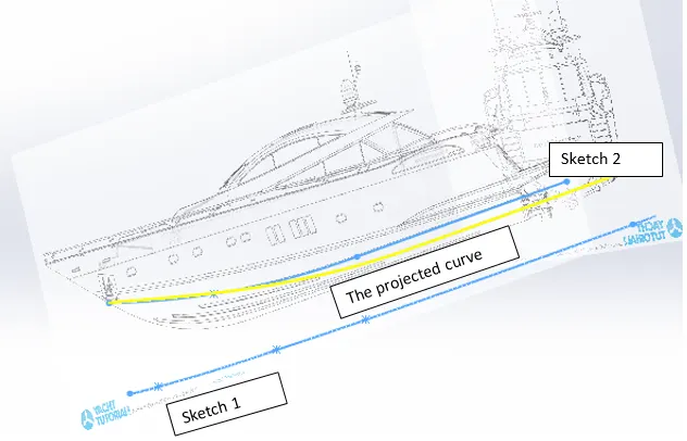
Fig 3.2: Projected curve used in modelling the base of the hull
Surface lofts were used to get surfaces with the desired profile and intended curvature was achieved with the help of proper guide curves.
All the surfaces were knit together and a solid was formed which was used for further processing.
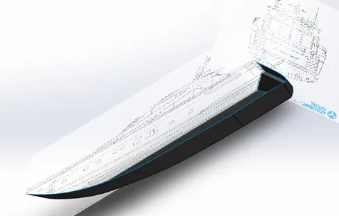
Fig 3.3: The surfaces used for hull modelling.
The railings were modelled using the sweep feature with projected curves used as path and circular profile.
Finally, a mirror was applied and proper appearances were added to the model as shown in the attached images.
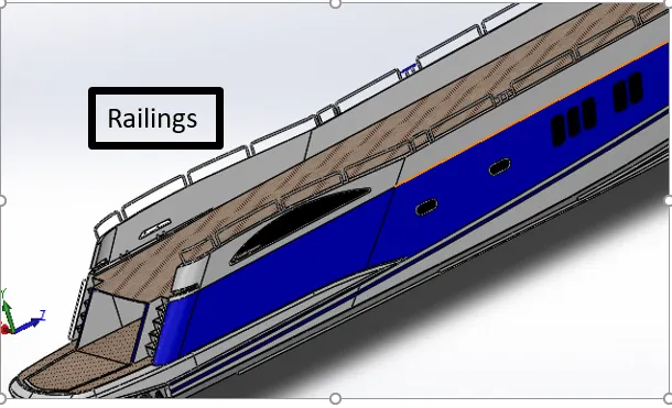
Fig 3.4: The railings visible in the model
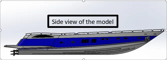
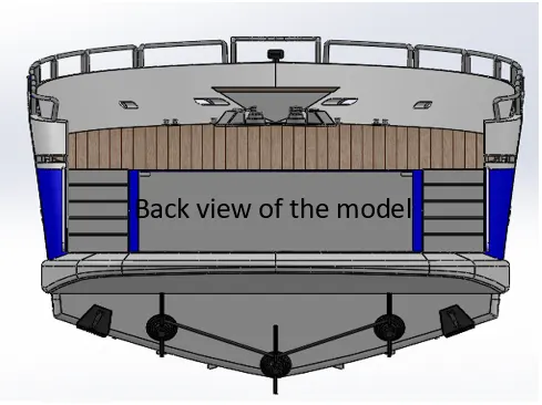
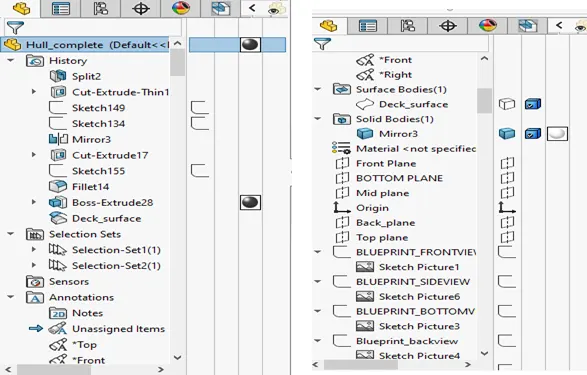
Fig 3.5: The feature tree snippets from the model.
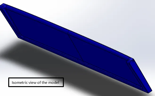
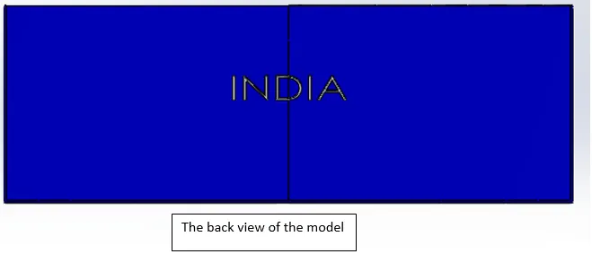
4. The Garage Door.
It was modelled using a cutaway stock from the hull. This stock was processed using extruded cuts and proper appearances were applied as shown in the attached image.
5. The Front Seat
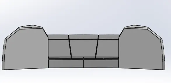
Modelling of the front seat was a mix of surface and solid modelling. This part also has symmetry about the midplane, so only half part was modelled and the other half was mirrored to get the complete model.
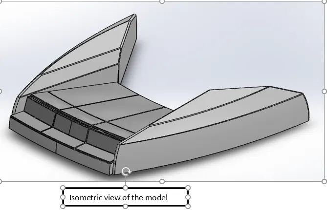
Surface modelling features include lofted surfaces, trim operations, surface extrudes and surface extends. Knit operations were performed to stitch all the surfaces into a single entity. The mattresses were modelled as separate bodies and proper fillets were applied to get the desired look.
6.The Middle Seat
The middle seat looks more like a typical sofa used as a furniture item. Most of the features are from solid modelling and does not include any complex shapes. The used features include extruded bosses, cuts and fillets.
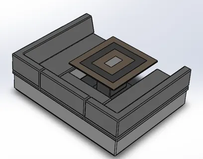
Isometric view of the model
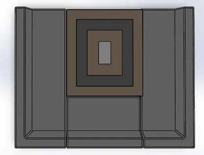
Fig 6.1: The isometric and top views of the model
7. The Rear Seat
It involves little bit complex features in comparison to the middle seat. Extensive use of surface modelling was made to get the curved portions of the seat.
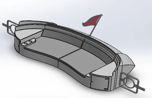
Fig 7.1: the isometric view of the model.
Fig 7.1: the isometric view of the model.
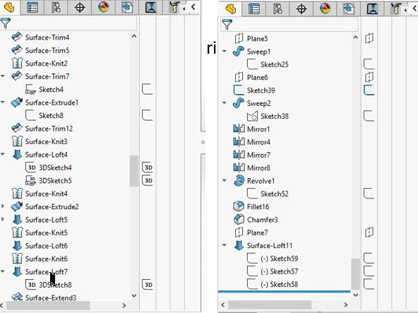
Fig 7.2: the feature tree snippets from the model
8. The Superstructure
It was the second most difficult part after hull. It involves a lot of curved faces which needs to be modelled as surfaces. Like most of the components, it also has symmetry about the mid plane. So, only half part was modelled and the mirror was used to get the complete model.
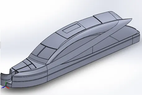
Fig 10.1: The half model of the superstructure
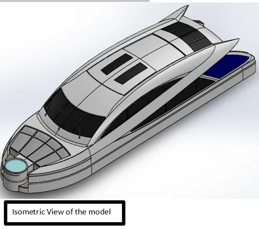
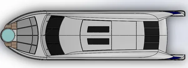
Fig 10.2: the isometric and top views of the model
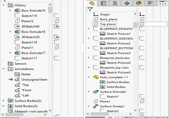
Fig 10.3: The feature tree snippets from the part
11. Radar mast and radar
After that, the next parts were the radar and the radar mast which were fairly simple in comparison to the superstructure and the hull. They involved simple features like an extruded boss, cuts and fillets. Their images are attached below.
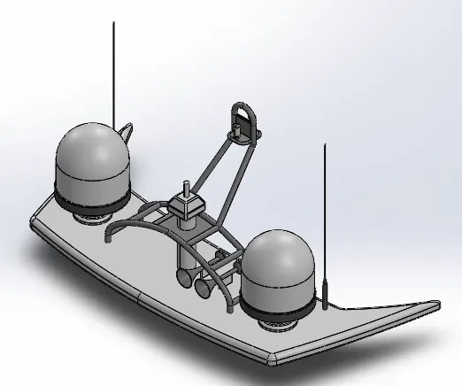
Fig 11.1: The isometric view of the radar mast
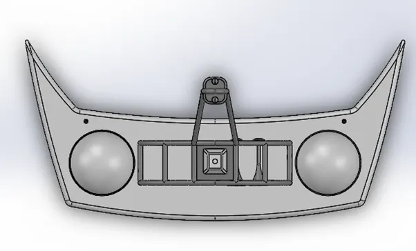
Fig 11.2: The top view of the model
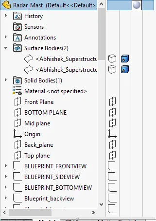
Fig 11.3: the snippet from the feature tree of the model
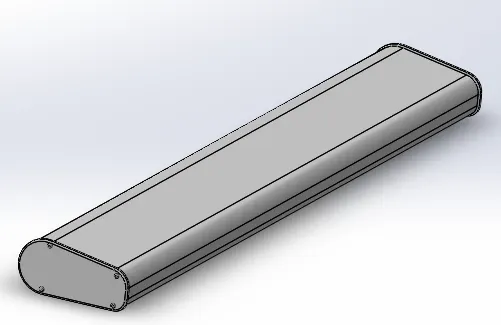
Fig 11.4: the radar
12. Assembly and Rendering
After completing the modelling of all the components, they were assembled together as explained in the below section.
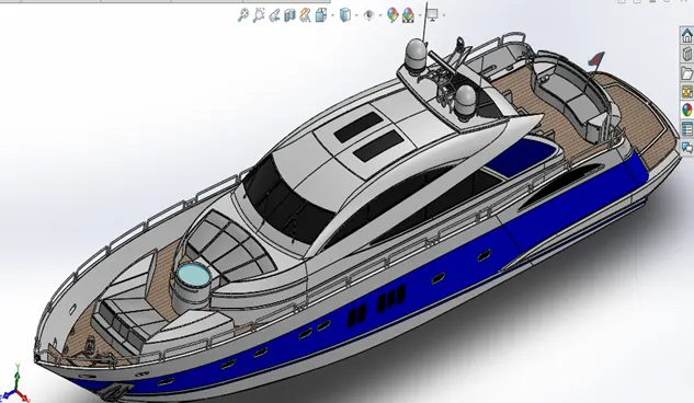
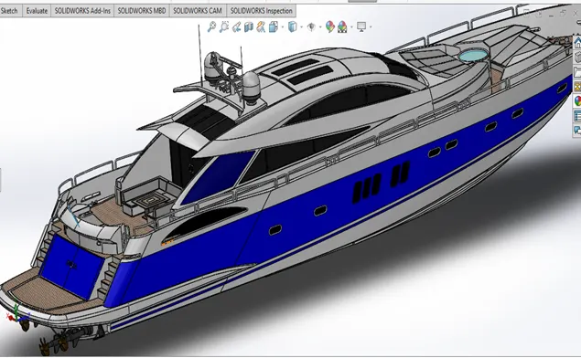
Fig 11.1: The assembled model.
The first part to be called was the Hull which was given the default position and acted as the base component. The next part was Superstructure which was also given default position for fixing. This worked as it was positioned according to the blueprints right from the part modelling.
Similarly, the front and the middle seats were fixed automatically while the rear seat was given additional distance mate and coincidence mate to fix it at the intended location.
Then all the propellers were called and they were fixed with a concentric mate for the shaft and hole as well as the coincidence mate for the bearing surfaces.
Next, the radar mast was called and was let to get automatically fixed. Finally, Radar was called and it was fixed to the mast shaft with concentric and coincident mates for the shaft and bearing surfaces.
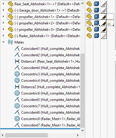
Fig 11.2: The mates applied between different parts
A basic rendering was done using Visualise. A total of 500 passes were used for getting the images attached below. The computer used was not capable of carrying out high-end renderings so the project was wrapped up with basic renders as shown below.
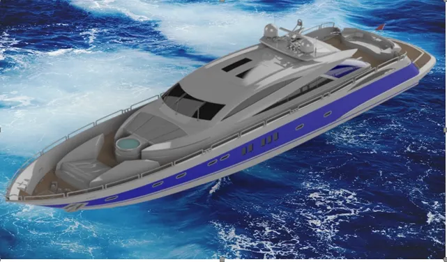
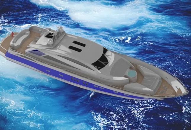
Fig 11.3: The rendered images
12. Conclusion:
This project was a detailed introduction to the various features and tools available in Solidworks for surface and solid modelling. There are a number of suitable ways to create an entity but choosing the best one from them takes experience and exposure to the software. This project was a very good lesson from that perspective. Overall it enabled me to use the tool effectively for carrying out modelling activities.
Thank you.