Week - 4 - 2D meshing for Plastic components
1.Introduction:
A bottle cap might seem like a simple component to cover the bottle, but from the perspective of a designer, it is a quite complex thing. It has threads that fasten it to the bottle. It also has a sealing mechanism in the form of locks that needs to be broken before use. So, there are several things that one can look for in a component as simple as a bottle cap.
In this exercise, a bottle cap model was meshed using ANSA software, a widely used pre-processing tool. Since all the features' thickness was far below 6mm, shell mesh or 2D mesh was used. In the following sections, all the steps are described accordingly.
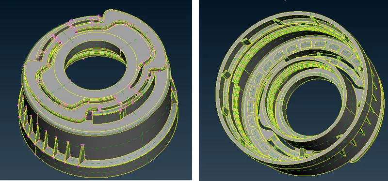
Fig 1.1: The CAD model of a bottle cap
2. Mid Surface extraction
First of all, the CAD model was checked for any irregularities like needle faces, cracks, duplicate surfaces or missing surfaces. This task gets simplified by using the check tool available in the software.
The next task is mid surface extraction which is basically getting a midplane out of the CAD model. There are several tools available under the faces tab of the topo module. The 'Middle' tool was used mostly for extracting mid surface from features with variable thicknesses.
Mid surface for some of the complicated portions can not be directly modelled using these tools. So they were constructed using new surfaces modelled with the help of appropriate curves. The 'Cons2Curve' tool available under the curves section of topo module is a very handy one for getting guide curves. There is a midline tool present under the curves section. It can be utilised to get a midline from the edges of a feature. This midline can be projected on the base mid surface. This operation creates a con or splitting line on the surface which can be used along with the midline to create a surface. The new surface becomes the mid surface of the feature after assigning proper thickness.
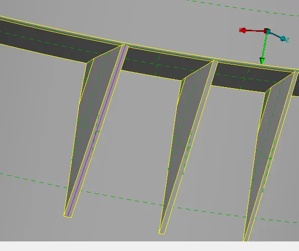
Fig 2.1: the midline created for rib
The thread cross-section was approximated to a rectangle as capturing a rhombus shape cross-section was not possible.
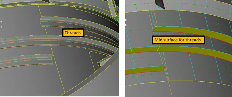
Fig 2.2: The mid surface for threads
All the mid surfaces were segregated into separate PIDs for the sake of convenience in assigning properties.
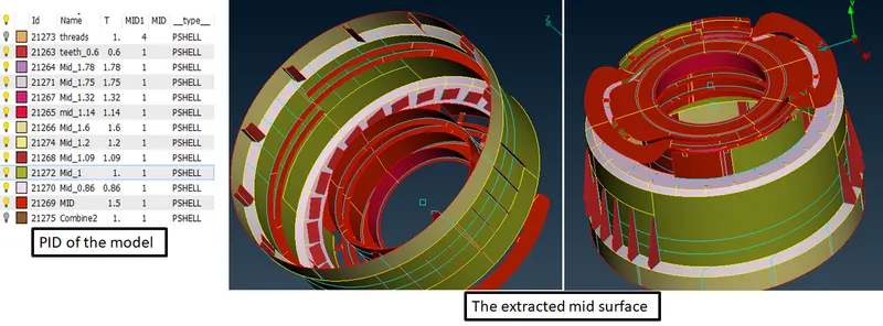
Fig 2.3: the mid surface
2.1 Geometry cleanup
The next step was cleaning up the mid surface according to the required quality criteria. This includes removal of sharp edges, a little bit of extension or modification to surfaces for saving elemental failures.
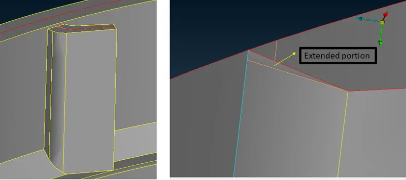
Fig 2.1.1: The extension of edge to avoid element failure
All these steps need to be performed according to the minimum size criteria required for the mesh. In our case, it was 0.5 mm so all the operations were done accordingly.
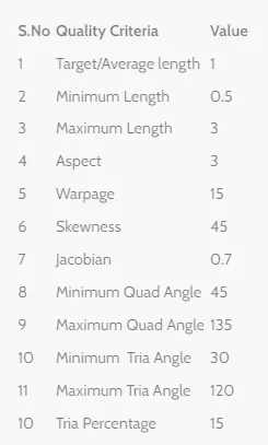
Fig 2.1.2: The quality criteria
The next step was mesh generation which is explained in the below section.
3. Mesh generation
After finishing the geometry cleanup, the mesh module was selected and the length command was used to provide a spacing of 1 mm to the hot points. Later on, the 'best' tool available under the mesh generation tab was used to create mesh on the surfaces. An optimum mesh was achieved using the 'Reconstruct' tool available under the shell mesh panel. The smooth command was used extensively to get a better mesh flow and correction of failing elements. (Picture)
Some features were similar and they did not need to be worked upon individually. Transform tool available under the utility section was used to create multiple copies of the feature along with the model. Here rotational symmetry was present so rotate command was used along with the proper axis of revolution defined using two centre points as shown in the attached figure.
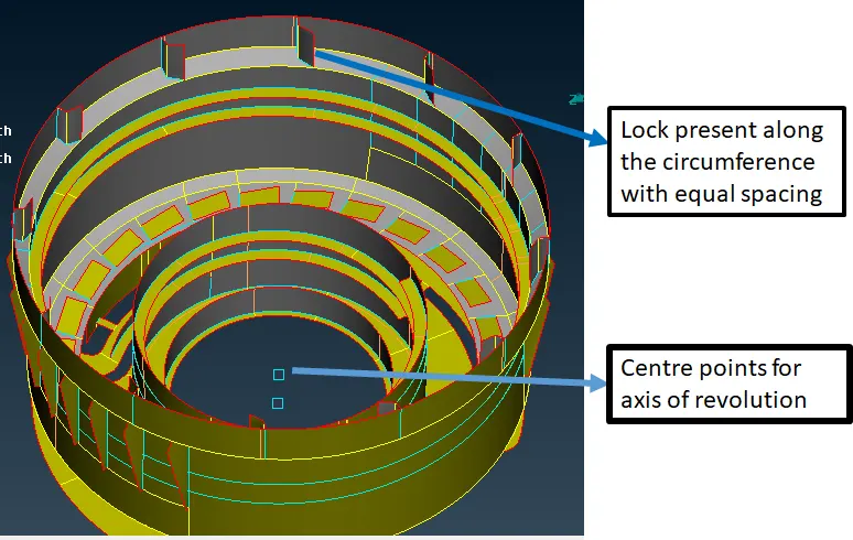
Fig 3.1: The presence of rotational symmetry
In some of the regions, elemental failures such as minimum length and aspect ratio could not be avoided due to geometry constraints. Modification to the model would have resulted in major changes to the features so the element failures were accepted.
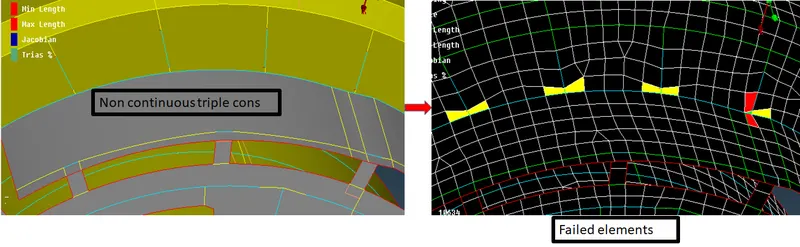
Fig 3.2: geometry constraints leading to element failures
This approach resulted in a total of 10785 elements.
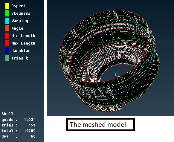
Fig 3.3: the generated mesh
After that proper thickness was assigned to all the regions from PID and default material present in the ANSA was assigned to them.
At last 'draw shell as solid' was enabled to visualize the thickness assigned to shell elements.
3. Conclusion
This exercise enabled me to use the tools available in ANSA to preprocess complex components with multiple intersecting features. It also exposed me to the rotation tool available in the transform tab. After working on such a model, one can easily understand the value of planning ahead of execution. There needs to be a proper strategy regarding how to capture the feature in the mid surface so that elemental failures can be minimised or if possible can be eliminated.
The model is attached for evaluation.
Thank you.