Week 12:Project-1-Meshing of Door Inner Panel Challenge
The Meshing of Door Inner Panel using Hypermesh
1. Introduction
A typical car nowadays contains almost 100-150 kg plastic in its body. They offer low weight and high moldability combined with adequate rigidity. In almost all cars, most of the inner panels are made of some sort of plastic material. In this exercise, the inner plastic panel of a typical passenger car door was meshed using hypermesh. Plastic components present in the cars are different from sheet metal parts in terms of thickness. In most sheet metal parts, the thickness remains constant throughout the body, but it varies from location to location in plastic components. This makes shell meshing or 2D meshing of plastic components difficult compared to sheet metal components. The difficulty arises in the extraction of the mid surface for the component. Automatic extraction algorithms do not provide satisfactory results hence the user needs to perform it manually.
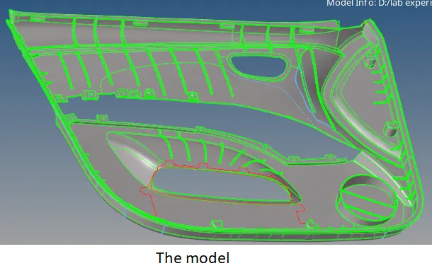
Fig 1.1: The inner panel
2. Mid surface extraction
All the mid surface extraction for the component was carried out manually using the offset tool available in the surface edit panel. For simplicity, the entire body was separated into two parts and they were moved into separate collectors as shown in the attached figure.
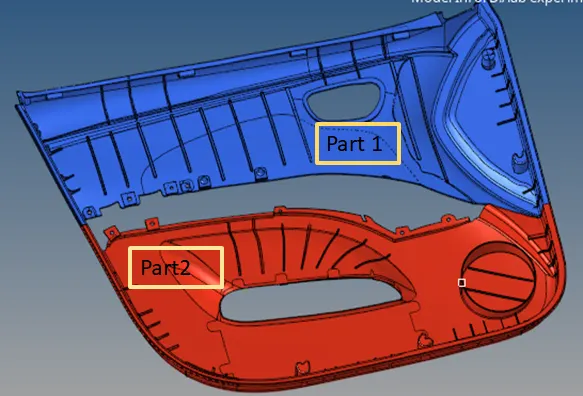
Fig 2.1: The model separated into two parts
After that manual offsetting of surfaces was started from part 2. Thickness was measured at suitable locations and surfaces were offset in the proper direction. All the surfaces of different thicknesses were put into separate collectors. This was done to assign different values of thickness to them. The model contained a lot of ribs and reinforcement structures. Mid surface extraction for these features was done by creating a new surface on the offset of bottom surfaces. The process involves creating a midline from edges then trimming the bottom surface with it and finally creating a surface between them using the ruled surface creation tool from the surface panel.
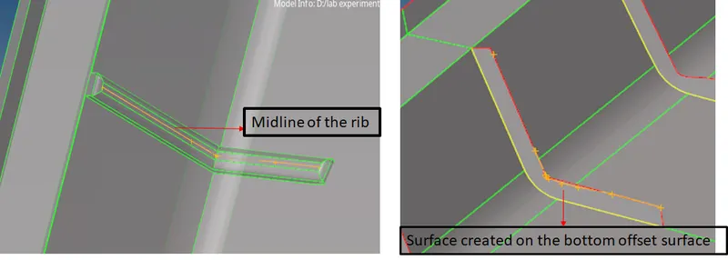
Fig 2.2: The mid surface extraction for rib using the midline.
At the edges of the component where it was not possible to extract two perpendicular surfaces in a single shot, offset for each surface was created separately. Then they were extended to intersect each other and a trim operation was performed between them. Extra portions were finally deleted to get the mid surface.
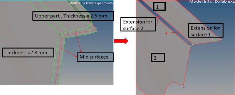
Fig 2.3: Schematic for mid surface extraction of two perpendicular surfaces
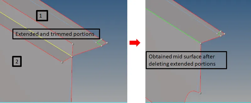
Fig 2.4: Extracted mid surface for perpendicular sections having different thickness.
Some of the features present in the model were represented by cross or simple plain surfaces as it was insignificant to model them for FE in their original shape. Some of the examples are attachment pins, separators used to ease the assembly of parts etc.
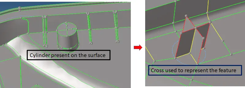
Fig 2.5: Modelling insignificant structures on the mid surface
A total of 7 different thicknesses in the range of 2 to 6 mm, were present in the model and mid surfaces from those portions were segregated into different collectors as shown in the attached figure.
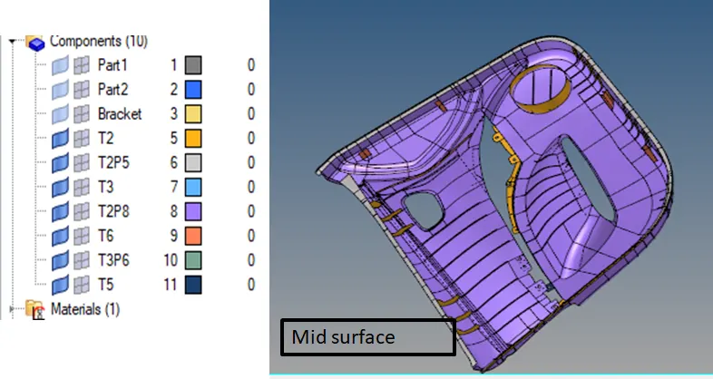
Fig 2.6: Segregation of extracted mid surface according to thickness.
After that, geometry cleanup was performed on the extracted mid surface according to the minimum and maximum lengths allowed in the quality criteria for mesh generation.
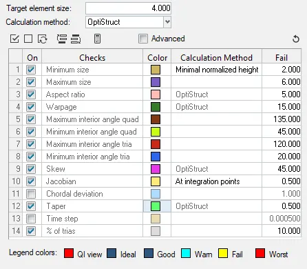
Fig 2.7: The quality criteria for mesh generation.
3. Mesh Generation
The next step was mesh generation on the mid surface. The mixed type with a target size of 4 mm was used for meshing of the surfaces. One of the common mistakes in mesh generation on the components with a higher number of features is the missing connectivity between mesh elements of adjacent portions. This mistake can be easily overcome by keeping the topology revision to 'advanced remesh' during the mesh generation. This menu can be accessed by pressing 'O' button or by going to the options menu.

Fig 3.1: The options menu and topology revision modes
Besides it, if there is a need to modify the geometry at a later stage during mesh generation, this mode can be toggled to 'keep mesh' to prevent changes in the generated mesh.
Other remedies to deal with missing connectivity include using the edge tool and equivalence options available in the same panel.
A total of 45110 elements made of 45621 nodes were generated on the component. Two of the elements failed for minimum length in near edge as shown in the attached figure. There was geometry constraint and hence they could not be corrected.
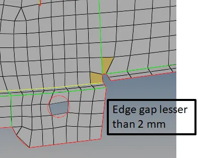
Fig 3.2: Elements failing for minimum length in a constrained area
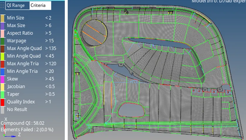
Fig 3.3: Mesh generated on the mid surface
4. Material and property
The next step was property and material assignment to the FE. A material named plastic was created with a rough estimation of the properties of ABS (Acrylonitrile Butadiene Styrene) and a total of 7 properties were created with different thickness. These properties were finally assigned to the respective collectors containing FE.
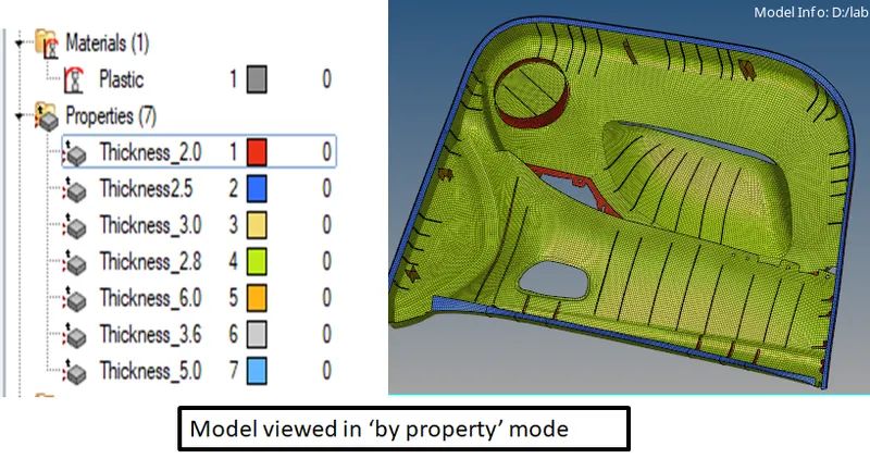
Fig 4.1: The properties assigned to the FE
5. Conclusion
After performing the above activity following points can be concluded:
1. Plastic components used in automobiles have varying thicknesses and they are often feature-rich which require careful mid surface extraction and mesh generation.
2. Geometry tools available in the Hypermesh must be mastered by a user to perform the mid surface extraction for complex parts like the one used in this exercise.
3. Separate collectors should be created for each thickness value and extracted mid surface should be put into them at the time of extraction itself to avoid confusion and rework at a later stage.
4. The location of elements should be kept at 'elems to original component' during mesh generation to avoid segregation task at a later stage.
The model is attached for evaluation.
Thank you.