Creating 1 D elements in Hypermesh
Week 4 Challange:
1. Importing geometry and Meshing:
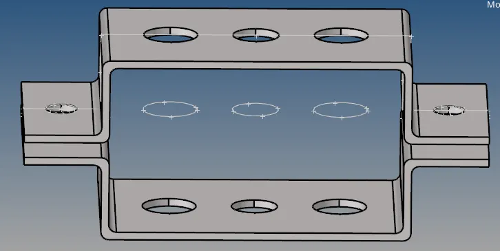
Fig 1.1: The imported geometry.
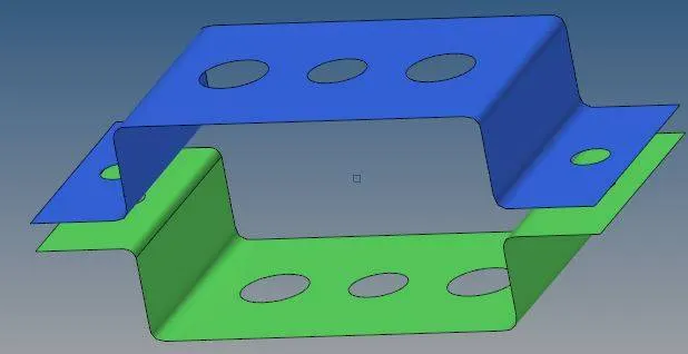
Fig 1.2: The created Mid Surfaces.
Mid Surface was created to avoid 3D meshing of the model. Mid surface creates shell element out of the selected 3D model.
The ectracted mid surfaces were made into two componenets namely Bracket 1 and Bracket 2.
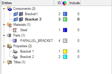
Fig 1.3: the fetaure treee of the model.
A new material was created with name of steel to assign to the created mid surfaces. Two properties were also created namely Bracket 1 and Bracket 2 as shown in the fig 1.3. The properties were assigned with the created material and after that they were assigned individually to Bracket 1 and Bracket 2 components. A thickness value of 2 mm was assigned to each of the properties.
washer split was used to capture the feature around holes. Washer split with lines and offset value of 5 mm was used around the holes.
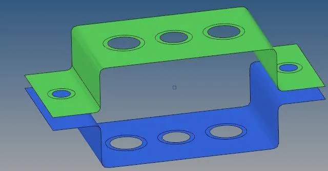
Fig 1.4: WAsher split created around the holes of the members of bracket.
1.2 Meshing
2D meshing was done using mix type of elements and a sizing of 5 mm. Number of elements around the holes were increased suitably to capture the features properly.
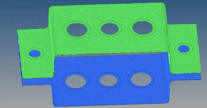
fig 1.2.1: The meshed model.
2. Creating 1D elements:
2.1 Creating Rod Element at location 'a'.
RBE2 links with all translation DOFs were created around upper and lower holes
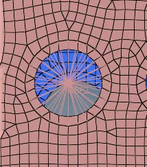
Fig 2.1.1: RBE2 link created around the upper hole.
Then in Hyperbeam a box section with dimensions as shown in the fig 2.1.2 was created and this beam section was assigned to a creted property named 'Rod at a' which was assigned to the created rod element.
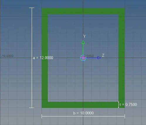
Fig 2.1.2: The cross section created in Hyperbeam.
1D detailed element representation was used to visualise the rod properly.
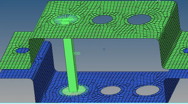
Fig 2.1.3: The created Rod element at location 'a'.
2.2 Creating Beam element at location B
RBE3 links were created at holes of location 2 with all the DOFs constrained. A bar element was created at the location and a beam section with I section as shown in the below fig 2.2.1 was created which was used to assign cross section to the created beam.
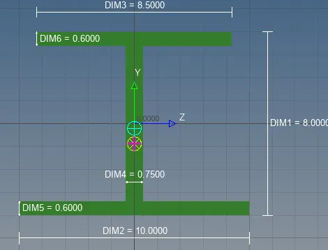
Fig 2.2.1: the created I section.
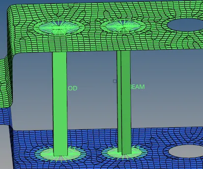
Fig 2.2.2: The craeted Beam at location B
2.3 Bar Element at locatio C with Cross shaped cross section
RBE3 links were created at the holes of location C. The elements were provided with translation as well as rotational DOFs in X and Y directions. Beam section with cross profile was created in Hyperbeam as shown in the fig 2.3.1 which was assigned to the craeted bar at the location.
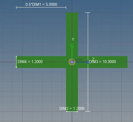
Fig 2.3.1: The cross section created in hyperbeam.
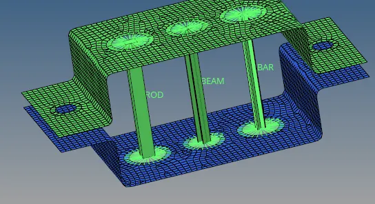
Fig 2.3.1: The bar element with cross type cross section created at the location C.
2.4 Applying masses at the locations D and E
RBE2 links were created at the holes of the location D and E. Mass elements with magnitude of 10 were added at the independent nodes of the creted RBE2 links at the holes.
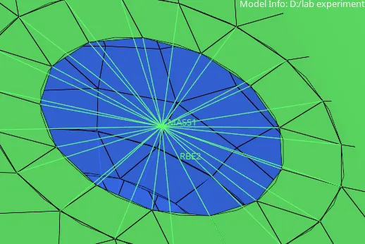
Fig 2.4.1: The created mass element at the independent node of the RBE2 link.
2.5 Applying spring elements at the locations F
Spring elements were added to the corners of the bracket at location F. They were created as CELAS1 elements and were assigned a property with a value of spring coefficient 100 units.
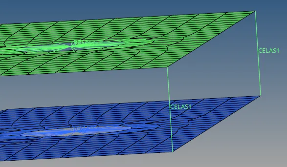
Fig 2.5.1: The spring elelments added to the edge of brackets.