Modelling of American Chopper in Solidworks
1. Title: Assembly of American chopper in Solidworks.
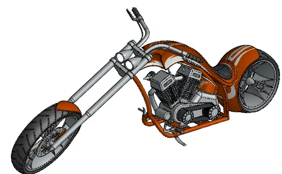
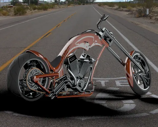
The different components of the american chopper model were modelled and they were assembled together in Solidworks. The assembled model was rendered using Photoview and Visualize.
2. Objectives:
- To understand the interface of the Solidworks software.
- To understand the 2D sketching process in the solidworks and different options to convert them into 3D bodies.
- To understand the special sketching features available in the Solidworks like projected curves, converting entities, offset entities etc.
- To understand the surface modelling in Solidworks.
- To understand the assembly of components inside Solidworks and editing of assembled components according to need inside the assembly.
- Rendering of models in Solidworks, introduction to photoview 360 and Solidworks Visualize.
3. Introduction:
In this module the modelling of different components of American Chopper and their assembly were carried out using SolidWorks software. After the modelling and the assembly of the chopper were done it was rendered using Photoview 360 and SolidWorks Visualise. A blueprint image as shown below was used to get guidance for sketching and modelling of components.
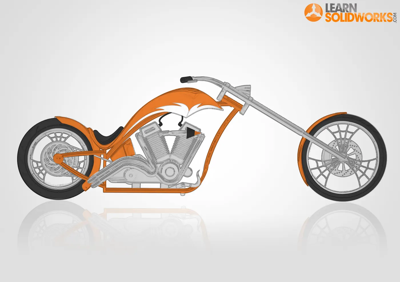
Fig 3.1: The image used as blueprint to model various componenets of the model.
The blueprint image was added using sketch picture option available under sketch tools and was scaled properly. It was set at a transparency of 40-50% to be able to view across it while modelling.
The modelling was done parametrically, whenever it was possible to do so. There were a total of 13 components which were modelled individually and were assembled together to get the final model of the American Chopper.
4. Design Methodology/ Approach:
Flow Chart of the modelling:
| Step | Brief Description | Snapshot |
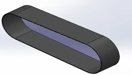
| 1. Modelling of transmission belt |
|
 |
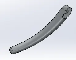
| 2. Modelling of Kickstand |
|
 |
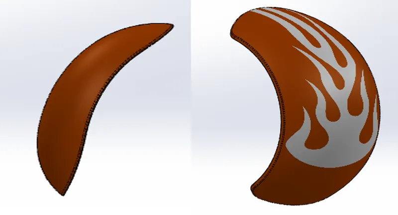
| 3. Modelling of Front and Rear Fenders |
|
 |
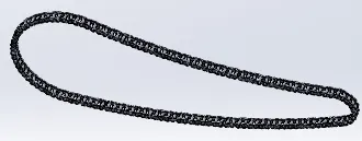
| 4. Modelling of Chain |
|
 |
| 5. Modelling of Oil Tank |
|
 |
| 6. Modelling of Pedal |
|
 |
| 7. Modelling of Front and Rear Wheels |
|
 |
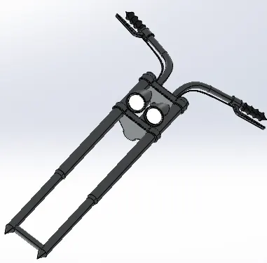
| 8. Modelling of Front Fork |
|
 |
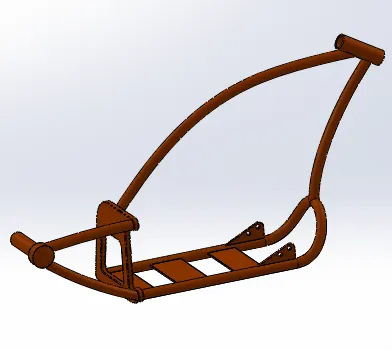
| 9. Modelling of Chassis |
|
 |
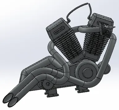
| 10. Modelling of Engine |
|
 |
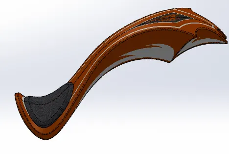
| 11. Modelling of Fuel Tank |
|
 |
| 12. Assembly of the Chopper |
|
 |
| 13. Rendering of the Chopper |
|
 |
5.Description:
5.1 Transmission Belt:
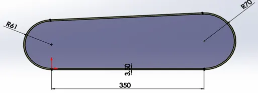
Fig 5.1.1: Sketch of the transmission belt
Sketch was created using two circles placed at centre distance of 350 mm. Tangent lines were drawn and unwanted portions were trimmed off to get the above shown sketch. Offset tool with a value of 3.5 mm was used to get the inner lining.
Extrude feature with a value of 88 mm was used to get the belt.
Fig 5.1.2: the extruded model of belt.
Matte Rubber was assigned as material for the belt.
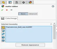
Fig5.1.3: Assignment of Matte Rubber to the belt.
5.2: Kickstand
A Loft was created along a guide curve with starting and end profiles for creating the kickstand body.
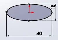
Fig 5.2.1: The starting profile for the loft created for the kickstand.
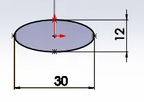
Fig 5.2.3: The end profile for the loft created for the kickstand body.
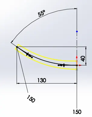
Fig 5.2.4: The spline created to act as the guide for the loft created for the loft.
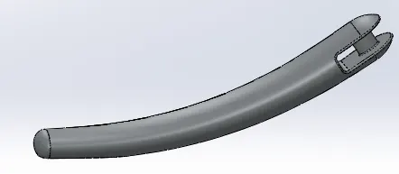
Fig 5.2.5: The created Kickstand body.
Additionally a cut was introduced to make the attaching point of the kickstand with the chassis of the Chopper.
Dome fetaure was used at the ends for rounding the ends. Fillets were applied at the edges cut for attach point and Chromium plate was applied as the material for it.
5.3 Front Fender:
Revolve and split were main features used for this part. A sketch was created on the front plane which was revolved to get the Fender body.
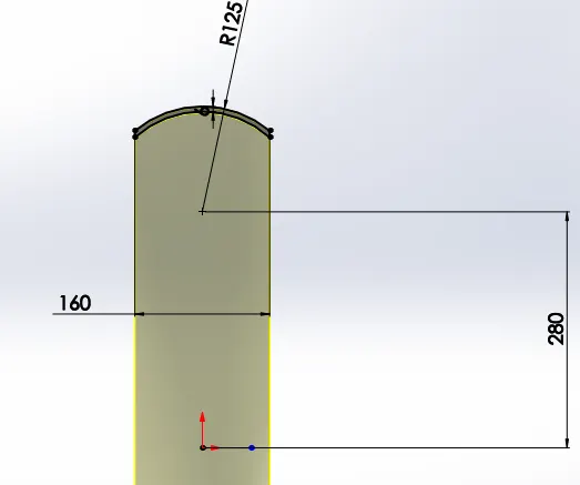
Fig 5.3.1: The sketch (in black) used to create the revolve for the Fender body.
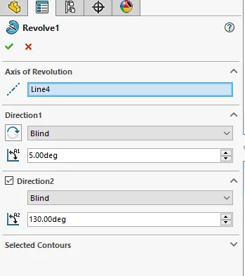
Fig 5.3.2: The values used for creating the revolve for the Fender.
A value of 5 degrees for the direction 1 while a value of 130 degrees was used for the direction 2. A temporary axes was chosen for the axis of revolution. Sienna was used as the appearance for the revolve.
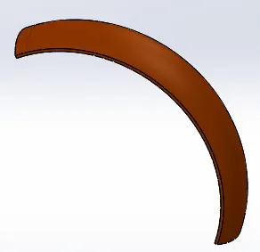
Fig 5.3.3: The created revolve for the part.
Split operations were performed to get the shapes at the ends of the fender.
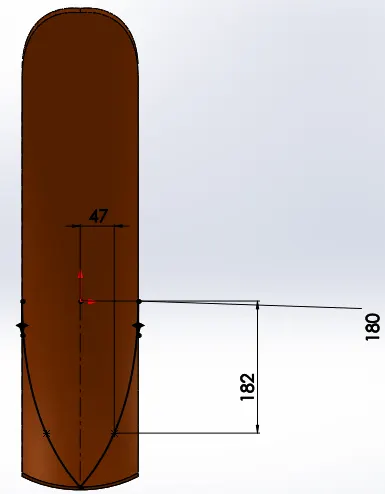
Fig 5.3.4: The sketch used to create the split for the lower end of the fender. The curvature of the created splines were checked to remove any inflexion point alog the curve.
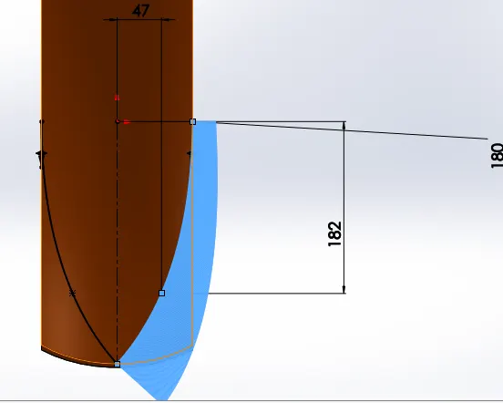
Fig 5.3.5: The curvature of the spline created for the cutturned on for inspection.
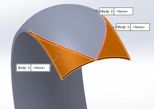
Fig 5.3.6: The Split operation window.
Consume cut body from the split window was used to remove the cut portion of the fender.
Similar operation was performed to get the cut the other end of the fender.
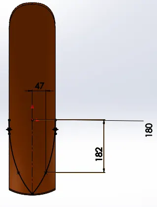
Fig 5.3.7: The sketch used to remove the extra portion from other end using split tool.
Finally fillets of 6mm were applied to the cut edges.
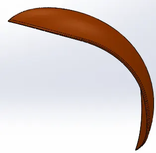
Fig 5.3.8: The front fender.
5.4 Rear Fender
The basic modelling for the rear fender is same as that of the front fender. A sketch on front plane was revolved to get the fender body.
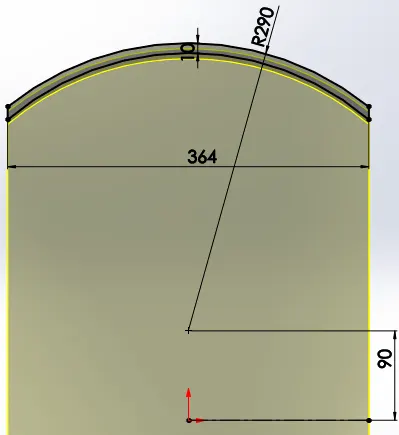
Fig 5.4.1: The sketch used for revolve.
The revolve was carried out for 10 degrees in direction 1 and 141 degrees in the direction 2.
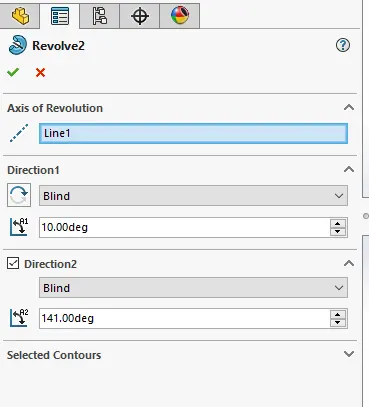
Fig 5.4.2: The settings used for the revolve.
Sienna was applied as the appearance for the part.
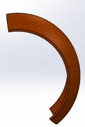
Fig 5.4.3: The revolve obtained after the operation.
After that Split operation was carried at one of the end to remove extra material from the solid.
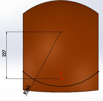
Fig 5.4.4: The sketch used for the split operation.
Ends of the 3 point arc used in the sketch were made coincident with the edges of the solid revolve body.
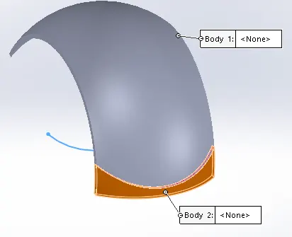
Fig 5.4.5: The portion removed using split tool. Consume cut bodies was enabled to get the desired part.
Fillets of 4mm were used on the edges and Shell tool with a value of 4 mm was used to remove material from the inner side of the revolve part.
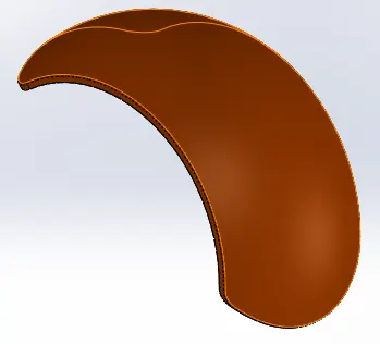
Fig 5.4.6: The final Rear fender
Decal was applied to it for rendering. Use Decal image Alpha Channel was used under mask image window to get the desired rndering of the fender. Projection type of mapping was used to get proper fit of the decal and the decal was mirrored vertically to get the proper orientation of the decal.
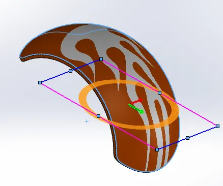
Fig 5.4.7: The Decal applied to the Rear Fender.
5.5 Chain:
Chain was created to connect the gearbox spocket with the rear wheel sprocket for power transmission. A cosmetic version of the Chain was created using an outlinee curve and pattern of individual inner and outer links of the chain.
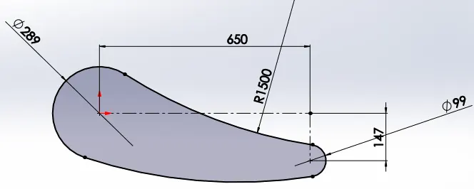
Fig 5.5.1: The outline sketch for the Chain
Then sketch blocks for inner and outer links of the chain were created.
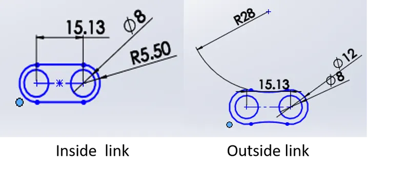
Fig 5.5.2: The inner and outer link sketch blocks.
For modelling the entire outline sketch and to negotiate the curves properly modelling was done in four parts namely upper arc, lower sprocket, lower arc of the lower sprocket and bigger sprocket.
The inner and outer blocks were placed on the outline sketch as shown in the figure and the parts of it were extruded separately.
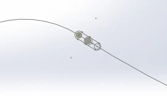
Fig 5.5.3: The inner and outer links placed along the outline sketch for upper arc of the outline.
Extrude operation was carried out in several parts. The first extrude was done for the rollers with a mid plane extrude with a value of 25 mm. Then the mid region was extruded for 2 mm by giving an offset value of 9.5 mm. IN the next extrude the outer link plate was extruded for 2 mm thickness. All the extrudes were done without using merge solids options to make them into separate solids. Fillets of 0.5 mm were applied and the extruded parts were made into a pattern along the outline curve.
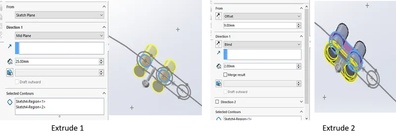
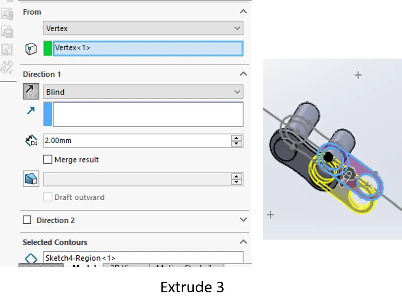
Fig 5.5.4: The extrude operations carried out.
Then pattern was created with spacing of 30.26 mm and 65 instances to get the pattern for the first part.
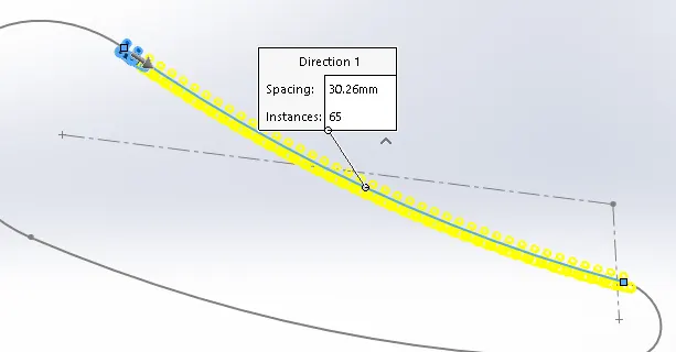
Fig 5.5.5: The pattern created for first part.
Similarly Sketch blocks were placed and extruded followed by curve driven patterns for the remaining three portions of the chain.
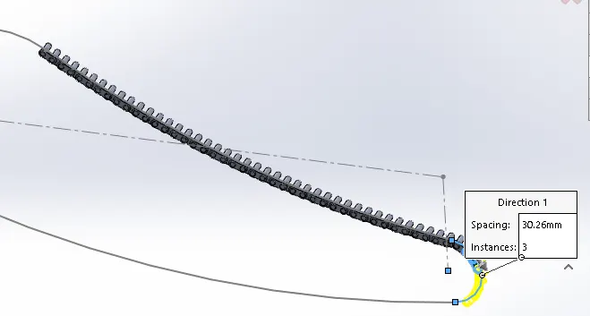
Fig 5.5.6: The second pattern for the chain.
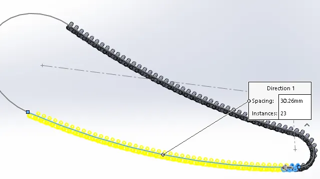
Fig 5.5.7: The third pattern made for the chain
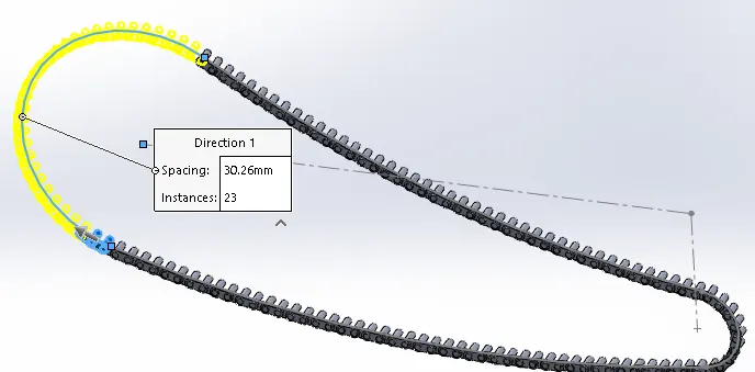
Fig 5.5.8: The final pattern for the chain
The final inner link connecting the chain was deleted from patterned links and it was sketched to get proper connectivity and was extruded afterwards. This was done as there was apparant interference between the final link an its adjacent links.
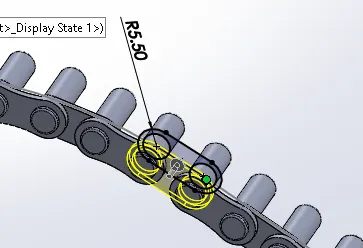
Fig 5.5.9: Modelling of the final link
There were a total of 390 solid bodies created so far and they were sorted into two folders for convenience. Pins or rollers were kept in one folder while the inner and outer plates were kept in the other folder.
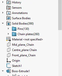
Fig 5.5.10: The folders of solid bodies named as pins and chain plates.
Finally The chain plate folder contents were mirrored along the mid plane to get the complete chain.
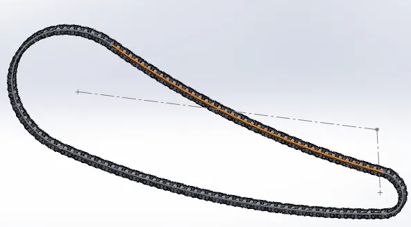
Fig 5.5.11 The final chain model.
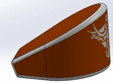
5.6 Oil Tank
Combine feature was used to get the desired shape of the oil tank while modelling it. Two features of the oil tank i.e. curve at the back and slant at the top face were made into the model using two solids with the respective features in them.
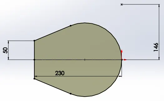
Fig 5.6.1: The sketch for first solid.
Dynamic mirror tool was used while sketching it so that only half portion was modelled and the other half got automatically created.
The created sketch on the top plane was extruded for 170 mm in direction 1 and 10 mm in the direction 2.
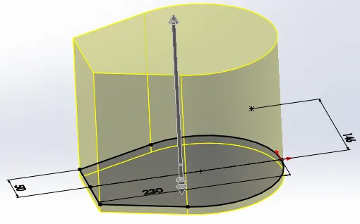
Fig 5.6.2: The extrude operation for solid 1.
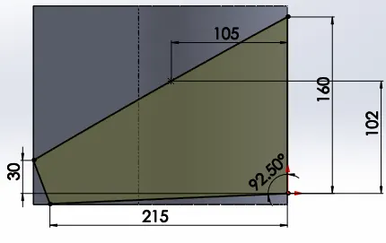
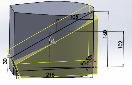
Fig 5.6.3: The sketch and extruded solid for the second solid (in yellow)
The second solid was created with through all option for both the directions. The merge tesults option was not selected to keep the two solids as separate bodies.
Then Combine tool was used to combine the two created solids. Operation type for the combine was selected as common to get the resulting solid as having features from both the solids.
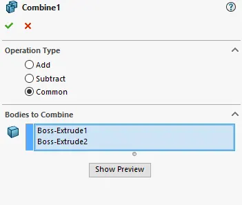
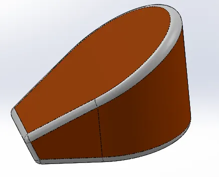
Fig 5.6.4: The resulting solid and sienna appearance applied to the body while white colour to the 10 mm fillet applied along the edges.
Finally Shell tool with 3 mm thickness value was used to make the component into a hollow tank.
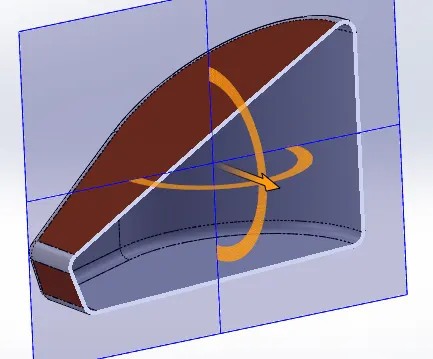
Fig 5.6.5: The created shell was checked for proper creation of hollow part using the section view tool.
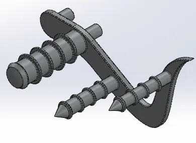
5.7 Pedal
A new feature used for creating this part was linear pattern and most of the parts were extruded from sketches.
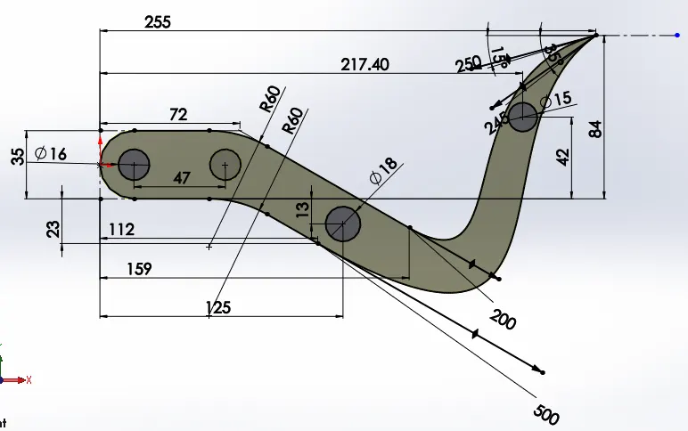
Fig 5.7.1: The sketch used for extruding various parts of the pedal.
In the first go entire sketch profile was extruded for 8 mm to get the base plate of the pedal.
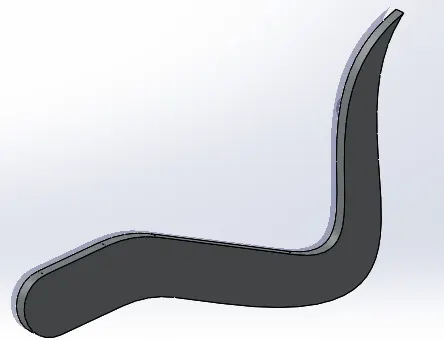
Fig 5.7.2: the base plate of the pedal created in the first extrude.
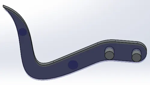
Fig 5.7.3: The second extrude of 20 mm for creating mounting peg of the pedal.
Next revolve tool was used to get the first shifting peg of the pedal. dome and fillet were used to smoothen the outer end of the revolve.
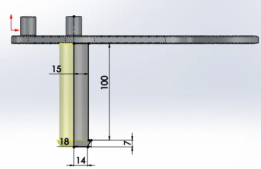
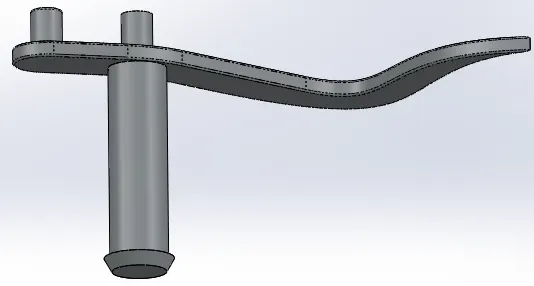
Fig 5.7.4: The Sketch and the resulting revolve for the first shifting peg of pedal.
In next extrude two more pegs of the pedal were extruded and chamfer was used to get pointed shape at their ends.
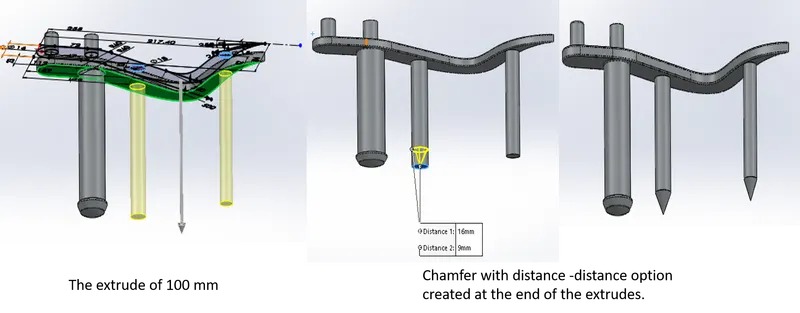
Fig 5.7.5: Second extrude and chamfer aplied to its end.
Thenafter third extrude was created with the purpose of getting the rings on the pegs as shown in the fig 5.7.6. An offset value of 20 mm from the sketch plane was used to position the rings.
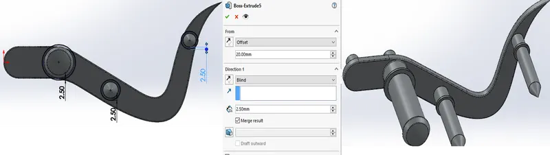
Fig 5.7.6: The sketch and extrude settings for the rings.
1 mm fillet was applied to all the edges and linear pattern was created to get the rings on the pegs.
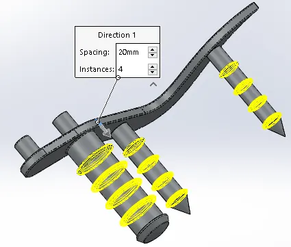
Fig 5.7.7.: the linear pattern used to get the rings along the pegs.
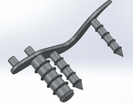
Fig 5.7.8: The final model of pedal
Chrome was assigned as material for this part.
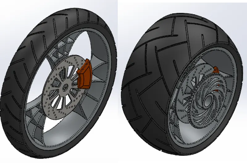
5.8 Front Wheel
The rim and hub of the wheel were created first and then tyre and its tread were created. Revolve feature was used to create the rim and hub of the wheel.
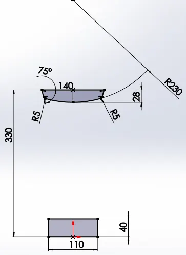
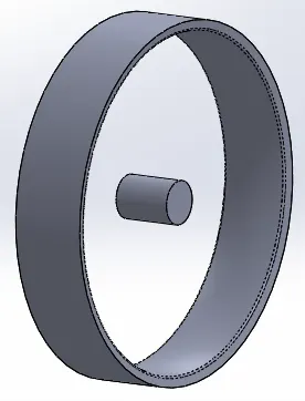
Fig 5.8.1: The sketch for revolve and the resulting body.
Then the block for spoke was sketched and was created using extrude with avalue of 120 mm.
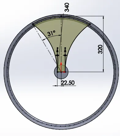
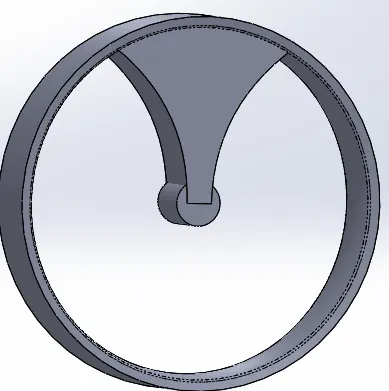
Fig 5.8.2: The sketch for spoke and the resulting spoke afterextrude operation.
Then extra material from the spoke was removed for getting spider web like shape of the rim. For carrying out this operation a sketch was made on the spoke and extruded cut was made in the shape of the sketch. For carrying out the extrude, selected contour option was used to select only the internal closed profiles
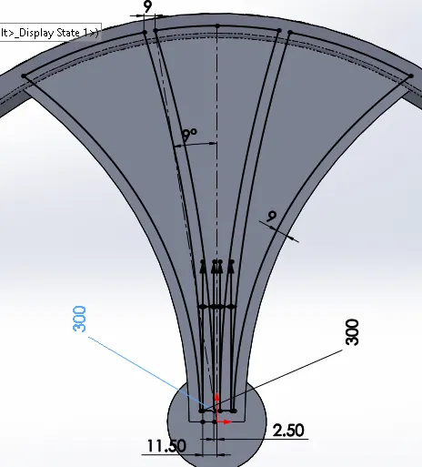
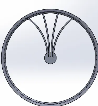
Fig 5.8.3: Sketch and the extruded cut for material removal from the spoke.
Then to get the connecting link between thode forks sketch was created and it was extruded with upto vertex options.The resulting solid was merged with only the spoke and not the hub and rim.
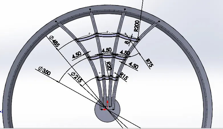
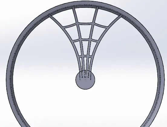
Fig 5.8.4: Sketch and extruded solid for the connecting links of the spoke.
After that extra material from the spoke was removed using a revolve cut carried out with a sketched profile on the front plane.
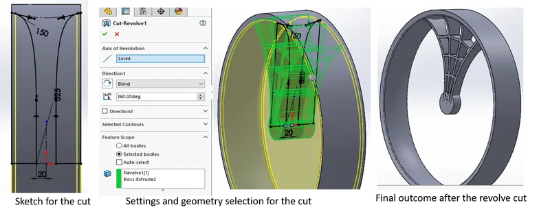
Fig 5.8.5: Material removal from the spoke and hub of the wheel.
Then circular pattern of the spoke was created with 3 number of instances.
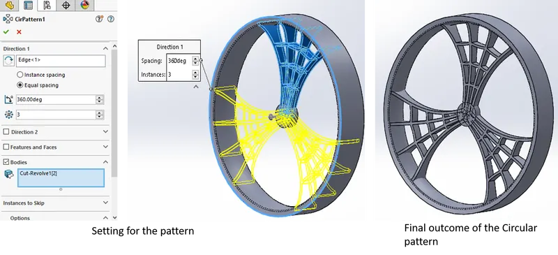
Fig 5.8.6: The circular pattern settings and its final outcome.
Then all the solids created so far were combined into a single solid using Combine feature. Add type of operation was used to get the bodies into a single solid.
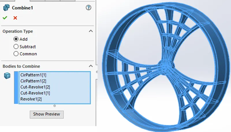
Fig 5.8.7: The combine feature used for gettting all the solids into a single one.
4 mm fillet was applied to all the created edges of the spoke. Then A disc was created for making rotor of brake using extrude feature feature.
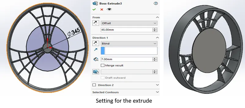
Fig 5.8.8: The extrude operation for the rotor disc.
Holes were created in the rotor disc for material removal which is basically done to enable better heat dissipation from the surface of the disc in the event of braking of the bike.
For creating the sketch for holes, a 8mm circle was made into a linear sketch pattern with 4 number of instances as shown in the figure 5.8.9.
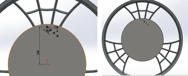
Fig 5.8.9: The holes created for material removal from the disc.
After that the holes were made into a circular pattern with 14 number of instances as shown in the fig 5.8.10.
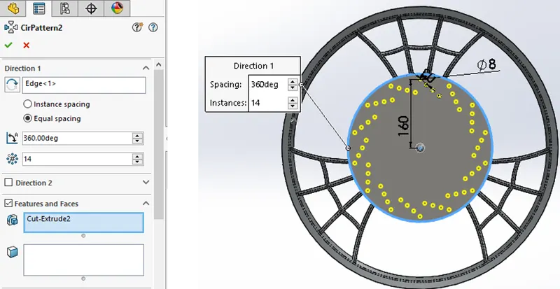
Fig 5.8.10: The setting and preview of the circular pattern created for the rotor disc holes.
Next a pattern of cut was introduced for further removal of the material from the disc.
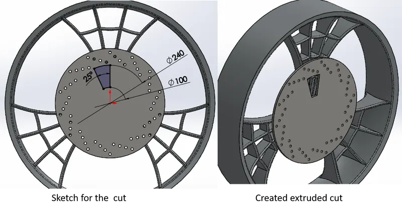
Fig 5.8.11: The sketch and performed cut for the material removal.
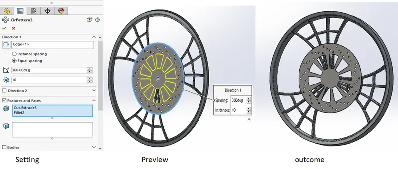
Fig 5.8.12: The preview and the pattern for the cut.
Then the process for making brake caliper was started. Its sketch was made and an extrude was made to get it.
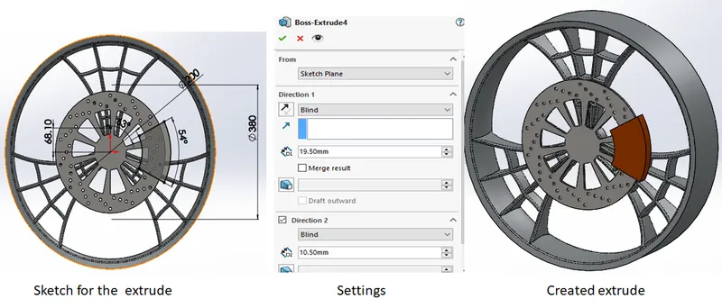
Fig 5.8.13: The sketch and the values used for performing the extrude for caliper. Then
Sienna apperance was applied to it.
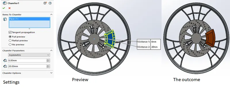
Fig 5.8.14: Settings and outcome for the chamfer applied to the caliper.
Then edge fillet of 8 mm was applied to the corners of the caliper created for brake.
After tyre was created using revolve feature. A sketch was created on the front plane and it was revolved to get the tyre on top of rim.
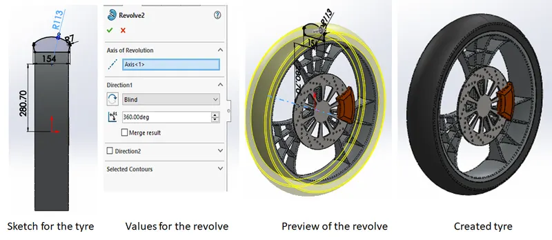
Fig 5.8.15: Sketch and setting for creating the revolve of tyre. Matte Rubber was assigned to the created tyre revolve.
Final step in the creation of the front wheel was the treads on tyre. For it sketch was created on front plane and extrude cut operation was performed with an offset value of 450 mm from the sketch plane. For direction of cut offset from surface was chosed and the surface for the same was selected as the tyre surface. The attached fig below shows the process.
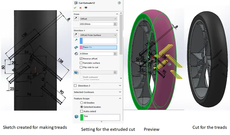
Fig 5.8.16: Process for creating the tyre treads.
Next the cut created in the previous step was made into a circular pattern after applying 4 mm fillet to all the created edges. Circular edge of the rim was chosen as the direction for the pattern. Fig 5.8.17 explains the process in detail.
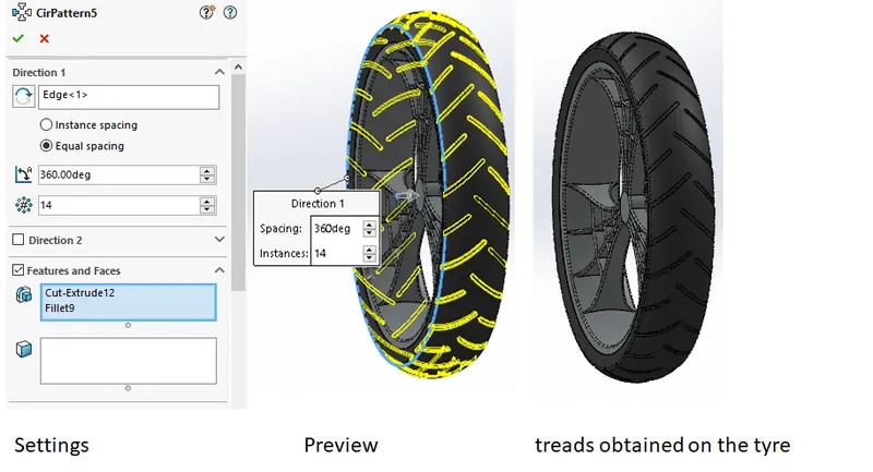
Fig 5.8.17: THe process of creating pattern of the treads.
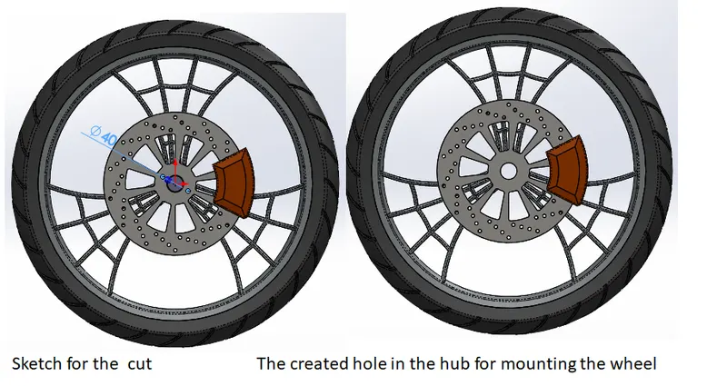
Finally a hole in the hub of the wheel was created for mounting the wheel in the chassis. The figure 5.8.18 shows the sketch and the extrude dreated with through all option selected for direction.
5.9 Rear Wheel
Basic process for creating the rear wheel was similar as that of the front wheel of the bike. First of all the revolve feature was used for getting the solid for the rim and the hub. 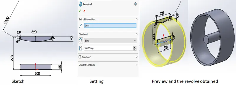
Fig 5.9.1: The process for the revolve used to get the rim and hub of the rear wheel.
This process resulted in two solids which were named as hub and rim respectively. Then the process to get the spokes of the wheel was started. a sketch as shown in the below fig 5.9.2 was made on the front plane and it was extruded 300 mm using midplane option to get the solid for further processing.
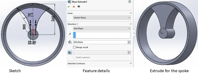
Fig 5.9.3: Process for the spoke of rear wheel.
After that the process to remove extra material from the screated spoke was started. A sketch was created on the face of the extrude using convert entities, offset and mirror entities options available for sketching.
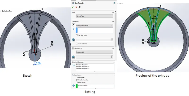
Fig 5.9.4: The sketch and settings used to get the cut for material removal.
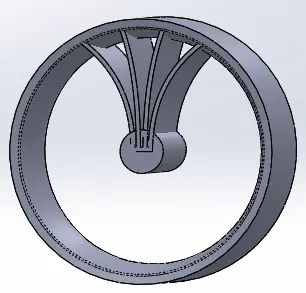
Fig 5.9.5: The obtained cut for the spoke.
After this the next step was to get the connecting links for the spider web design of the spoke. Sketch for getting the links was made on the front face of the spoke. Some of the features used for the sketch was offset entities and trim tool. Extrude feature was used with vertex option for both the directions. This was done to enable auto update of the extrude in the case of changes in the thickness of spokes.
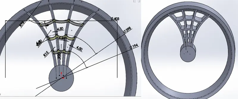
Fig 5.9.6: The sketch and the extrude obtained for the connetcing links.
Then the created spoke was made into a circular pattern with number of instances set to three.
Then combine operation was used to combine the spokes and hub into a single solid. After that a revolve cut was used to remove extra material from the entire spoke and to get the desired shape of the spokes.
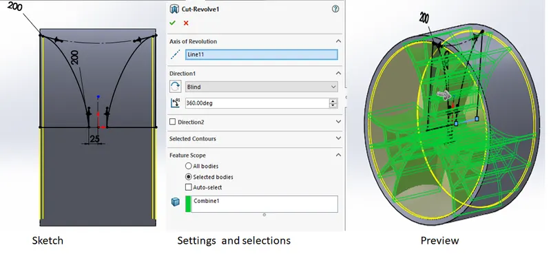
Fig 5.9.7: The sketch, selections and preview for the revolve cut performed to remove material from the spokes of the rear wheel.
After that 3 mm fillet was applied to all the edges of the spokes and a hole was created at the hub for mounting of the rear wheel.444
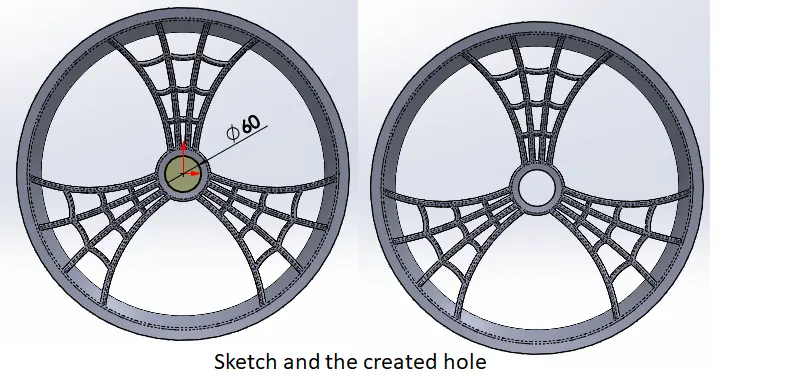
Fig 5.9.8: The sketch and the created hole using extruded cut feature for mounting of the rear wheel.
Next a sketch was created on the front plane for creating the revolve for hub of the wheel along with pointed shape at the back side. This sketch was made into a 360 revolve to get the desired shape for the hub. merge result was enabled and under feature scope, the hub and spokes were selected.
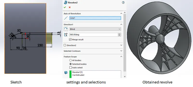
Fig 5.9.9: The sketch and the created revolve for the hub of the wheel.
After that the process for getting the rotor disc was started. A disc was extruded out of a circle sketched on the right plane. A 7mm extrude was made from the circle.
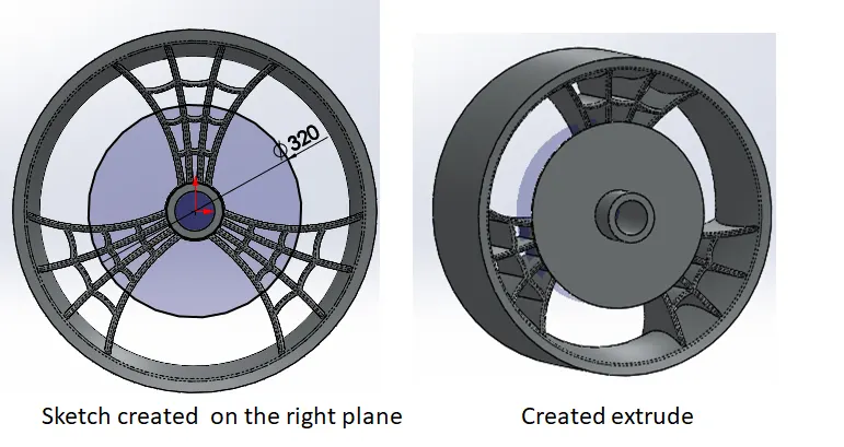
Fig 5.9.10: the process for getting the rotor disc.
Then holes were created in the created rotor disc and was made into a 360 degree circular pattern with 14 number of instances to get the pattern of holes on the disc.
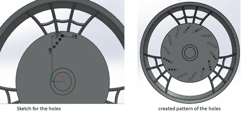
Fig 5.9.11: The pattern of holes created in the disc.
Further material removal from the disc was done in the form of a pattern of cut as shown in the fig 5.9.12. The number of instances for the circular pattern was set to 9 just like the one done for the front wheel.
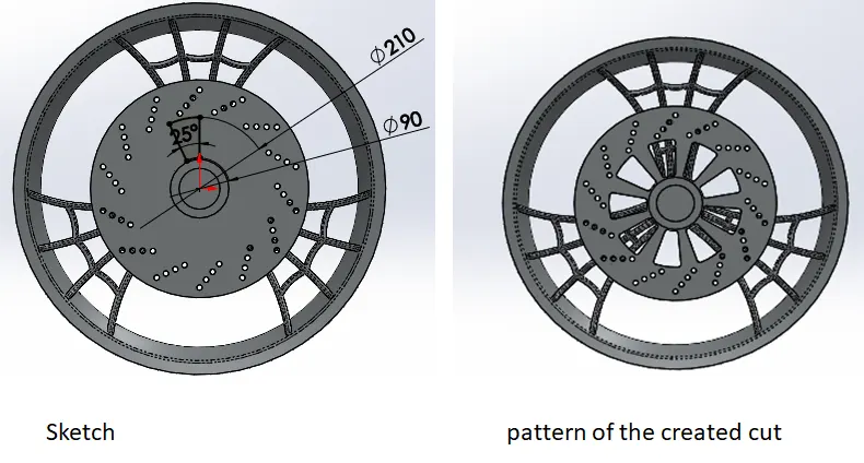
Fig 5.9.12: The material removal from the rotor disc in the form of a pattern of cut.
Next the caliper of the brake was created using extrude feature and it was assigned sienna appearance. The fig 5.9.13 explains the process for creating the caliper.
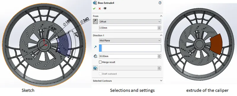
Fig 5.9.13: the process of getting the caliper on the rotor disc.
After that chamfer was created on the faces of the caliper with the settings shown in the below figure.
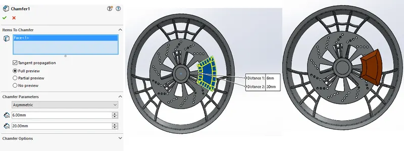
Fig 5.9.14: The process for getting chamfer on the face of the caliper
Fillets were applied appropriately on the edges created as a result of the chamfer operation. After that the process for getting the sprocket on the rear wheel was started. A disc was first extruded to act as the gear blank for sprocket.
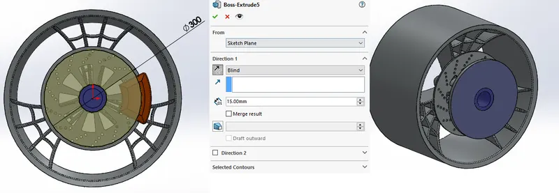
Fig 5.9.15: The process for getting the blank disc for the sprocket.
Then a chamfer was created on the periphery of the created blank. Both the edges of the periphery were selected and distance angle method with avalue set of 4 mm and 45 degree.
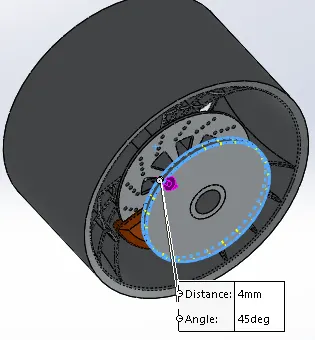
Fig 5.9.16: Chamfer preview
After that a sketch was made on the face of disc as shown in the fig 5.9.17. This cut was then provided with an edge fillet for the thickness edges with a value of 2.2 mm.
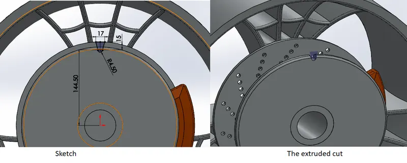
Fig 5.9.17: The extruded cut made on the face of the disc to get teeth on it.
Then a circular pattern of the cut was created with the settings as shown in the figure 5.9.18.
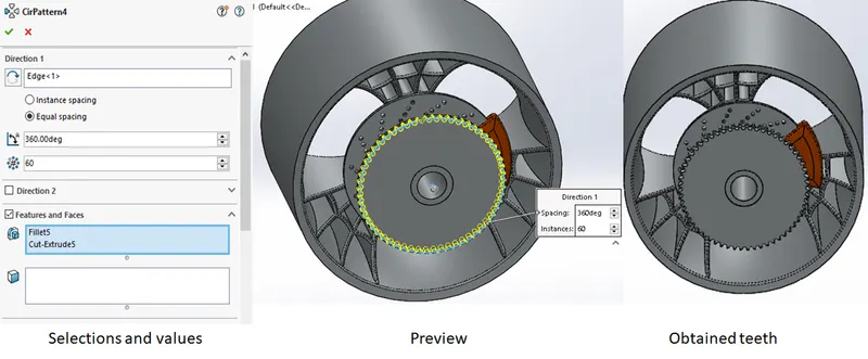
Fig 5.9.18: The pattern of cut created on the blank disc to get teeth for sprocket.
Next a pattern of two cuts was introduced for further removal of material from the sprocket disc. The figure 5.9.19 shows the process for first cut. Extruded cut was made with through all option.
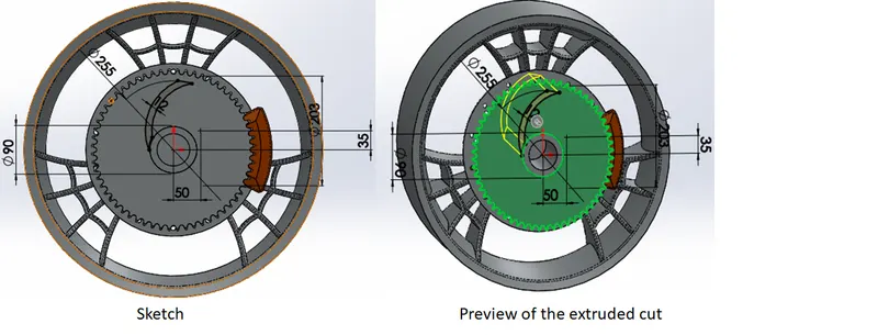
Fig 5.9.19: The first cut created for material removal
Next a similar cut was made on the disc. Below figure shows the sketch and preview of the cut.
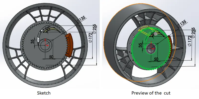
Fig 5.9.20: The second cut created for getting the pattern for material removal.
1 mm fillet was applied to all the edges of the cut. Then pattern of the two cuts was made with number of instances set to 7 and direction for the full 360 pattern set as the edge of the disc. Below figure shows the process.
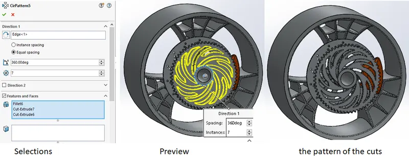
Fig 5.9.21: The pattern of cuts used for removal of material from the sprocket disc.
After that the tyre was created for the wheel. It was created using revolve of a sketch created on the front plane of the model. Below figure shows the process for getting the tyre over rim of the wheel. Matt rubber was assigned as material for the created tyre.
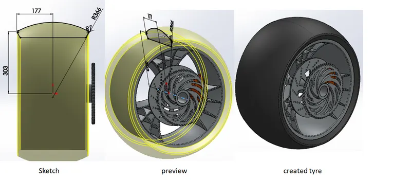
Fig 5.9.22: The process of getting tyre on the rim of the wheel.
The final step in rear wheel modelling was getting treads on the tyre created in the previous step. The process for getting it on the rear wheel was just like the one done for front wheel. below figure explains the process.
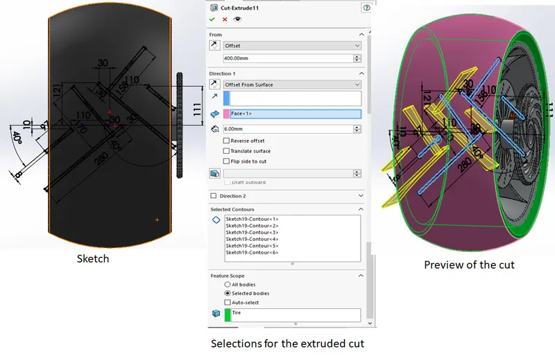
Fig 5.9.23: The sketch, Settings and selection and the preview of the cut created for treads.
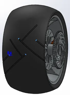
Fig 5.9.24: the highlighted edges of the cut were provided with fillet of 4 mm radius.
Finally a circular pattern of the created cut was made to get the tread along the tyre.
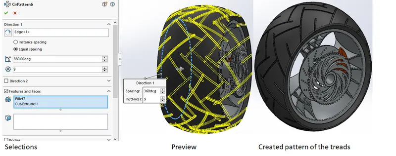
Fig 5.9.25: the process and setting for getting the pattern of the treads of the tyre.
The modelling of the rear wheel was complete after this step.
5.10 The Front Fork
The front fork of the bike contains handlebar, telescopic forks and the head lamp of the bike. Some of the features used for modelling it were sweeep, combine, revolve and extrude. The modelling was started by making half of the telescopic fork using revolve faeture.
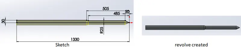
Fig 5.10.1: the sketch created on front plane and the revolve created.
Next half of the holding clamp for the front fork was modelled using extrude feature. The remaining half of the clamp was modelled using mirror feature. The sketch for the clamp was created on the circular face of the telescopic for and the extrude was made using a 20 mm offset of extrude down the fork, as clear from the below figure.
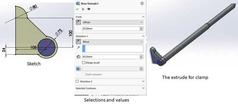
Fig 5.10.2: The process of getting extrude for the clamp.
After that 5 mm fillet was applied on the edges of the extrude. The face where mirroring was to be done was left without fillet. After that linear pattern was used to get another clamp down the telescopic fork with an offset of 240 mm. The below figure shows the process in detail. created clamp copy was merged with the original clamp extrude.
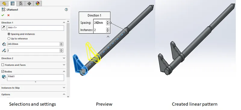
Fig 5.10.3: The process of getting linear pattern of the clamp extrude.
Next, another extrude out of a circle sketched on the front plane on the pointed end of the revolve was made as shown in the below figure and it was merged with fork as clear from the below figure.
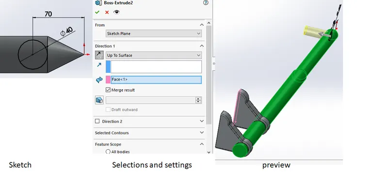
Fig 5.10.4: The process of getting extrude at the pointed end of the telescopic fork.
After that, half of the connecting link between clamps was modelled using extrude feature. The sketch for extrude was created on the front face of clamp in the form of half of a circle. The figure shown below provides process details for the extrude. Created extrude was merged with
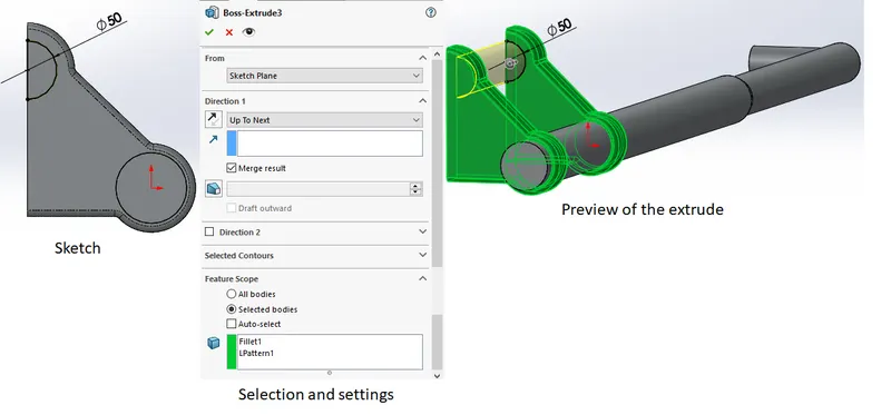
Fig 5.10.5: The process of getting extrude of connecting rod of clamps.
Then the process for modelling the head lamp bucket was started. It was made using the revolve feature. The sketch for revolve including the axis was made on the front plane and a full 360 revolve was made without chosing the merge result option to make it into a separate body.
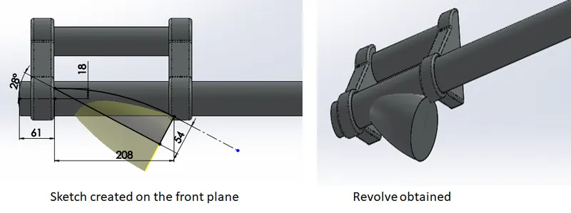
Fig 5.10.6: The sketch and extrude for head lamp bucket.
Then an extruded cut with draft was introduced to model the lens of the head lamp. Below figure shows the process for the same. This feature was merged with the revolve for the head lamp only.
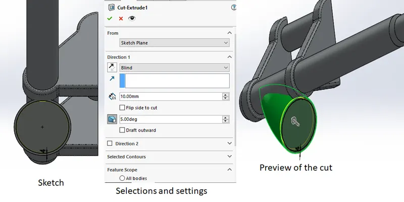
Fig 5.10.7: The process of getting the cut for lens in the head lamp bucket.
Then a fillet of 3 mm was applied on the edge of the cut created and a dome was created with a value of 7 mm on the face of bucket as shown in the below figure.
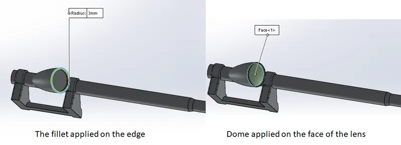
Fig 5.10.8: The fillet and the dome applied on the bucket face
Further, a 360 revolve cut was introduced for the lens of the lamp. For making this cut a triangle, as shown in the below figure, was sketched on the front plane and it was used to make a revolve cut. The created feature was merged with the head lamp bucket.
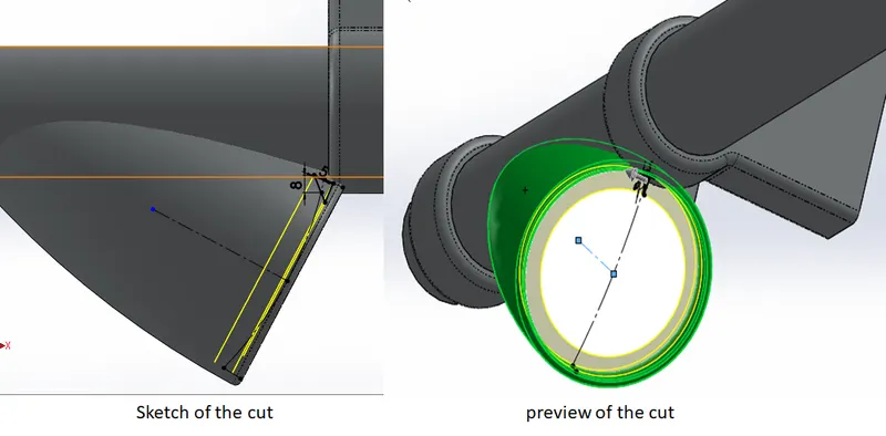
Fig 5.10.9: the sketch and preview of the cut.
After performing this cut, the bucket was moved in Z direction using move command for proper positioning of the bucket. This was done in order to align our bucket with the front plane.
The below figure explins the process in detail.
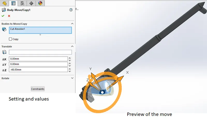
Fig 5.10.10: The values and preview of the move performed.
Then the process for modelling the handle bar was started. projection curve was used to get a guide curve which was used to create a sweep of circular profile. The below figure shows previes and sketch for getting the projected curve
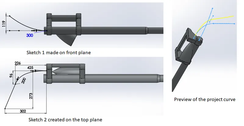
Fig 5.10.11: The sketches used and preview of the projected curve.
Next, a sweep as shown in the below figure was created for the handle bar.
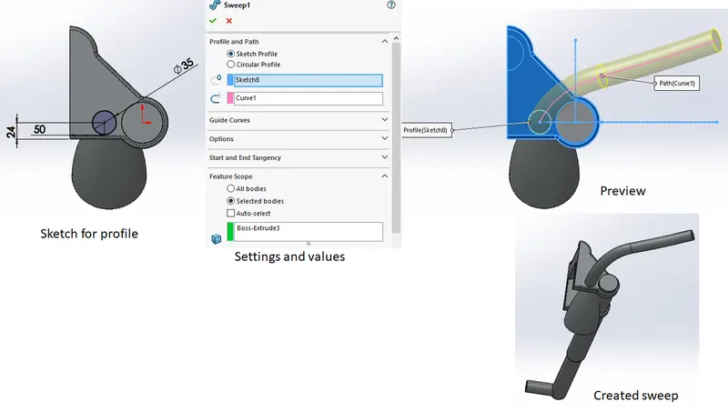
Fig 5.10.12: The sweep made for handle bar.
After that a plane was created on the cross section of the created sweep. it was done by creating a sketch on the end of the sweep which was used for making the plane. On the created plane a sketch was made for making a revolve to create the grip of the handle bar.
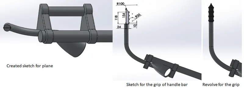
Fig 5.10.12: The revolve made for handle bar grip.
After that another revolve was added to the handle bar as shown in the below figure.
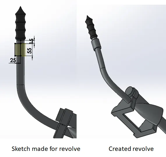
Fig 5.10.13: Another revolve added to the handle bar.
After that the process for creating the brake levers was started. First a plane was created using the plane used for sketch of grip and a temporary axis as the second reference with 160 degree rotation. The below figure shows the process in detail.
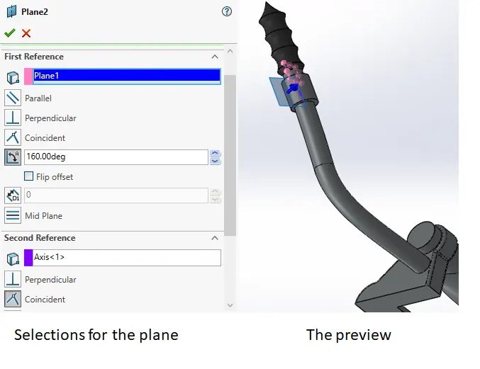
Fig 5.10.14: Plane created for the sketch of lever.
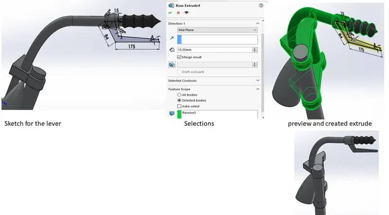
Fig 5.10.15: The sketch and extrude for creating lever
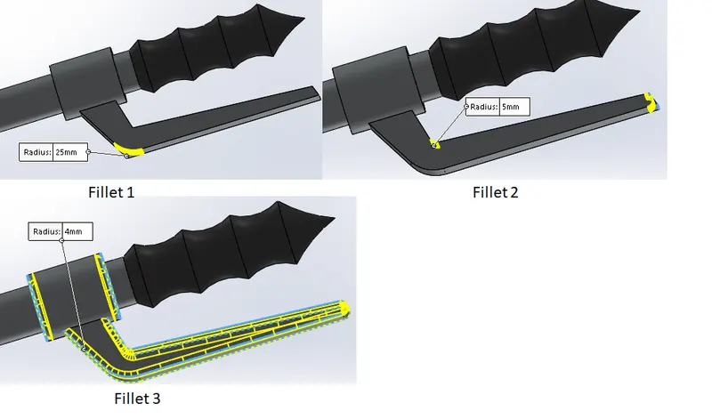
Fig 5.10.16: Fillets applied to the edges of the created lever
After that another projected curve from two sketches was made for modelling the cable of brake levers. The below figure shows sketches used and the created projected curve.
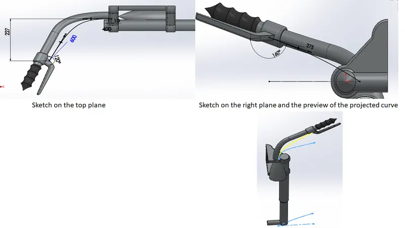
Fig 5.10.17: The sketches used and the preview of the projected curve
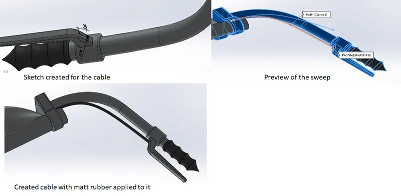
Fig 5.10.18: The created sweep for cable
After that a mid plane of the model was created for the purpose of mniiroring the created model. The below figure shows reference selections and the preview of the mid plane created.
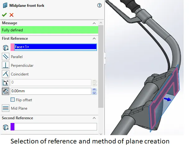
Fig 5.10.19: The mid plane created for the purpose of mirroring
Then the created model was mirrored along the plane created in the previous step. The below figure shows the details.
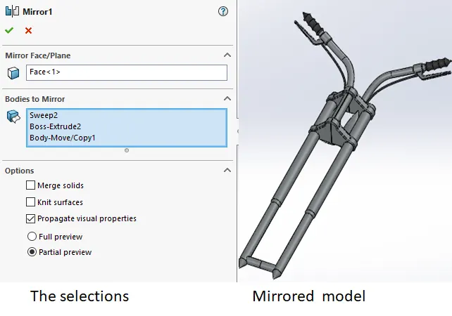
fig 5.10.20: The mirror created for the model.
Parting line along the mirror face can be seen in the above figure. It was removed using the combine operation for the clamp and for the forks separately as shown in the below figure.
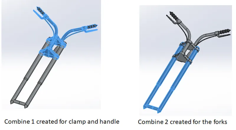
Fig 5.10.21: the combine operations used for creating the model.
Then a plane was created for the purpose of creating mates during assembly of the model. the below figure shows details of the created plane.
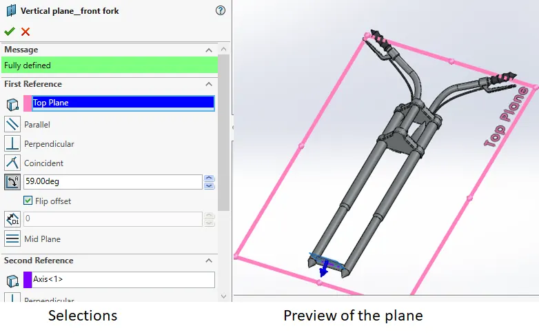
Fig 5.10.22: the created plane for the purpose of mating of parts during assembly.
Area light was applied to the lens of the head lamp for rendering. The below figure shows the details.
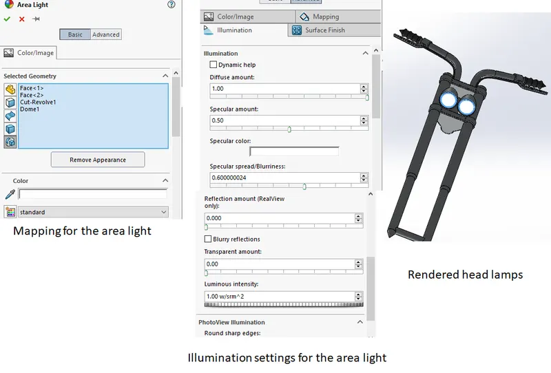
Fig 5.10.23: the details of the area light applied to the head lamp.
5.11 The Chassis
Chassis of the bike is like the main frame of the vehicle on which all other components are mounted. Most of the chassis is made up of pipes which are modelled using the sweep of a closed profile along a suitable guide curve.
Modelling was started by importing the blueprint picture for reference and starting with parallel members at the bottom.
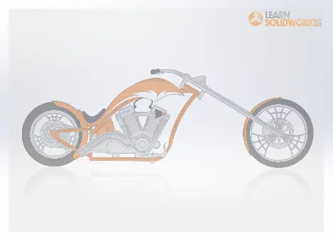
Fig 5.11.1: The imported blueprint picture
After that a projected curve from two sketches as shown in the below figure was created for the lower memeber.
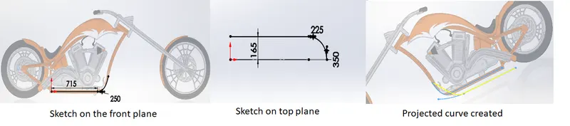
Fig 5.11.2: The sketches used for the projected curve and the resulting curve.
For better control of the bend at the front of the chassis the sketch created on the top plane was replaced with another sketch on the right plane at the back of the member. The sketch created on the front plane was again made into a sketch using convert entity to get a new sketch. Attached figure shows the details.
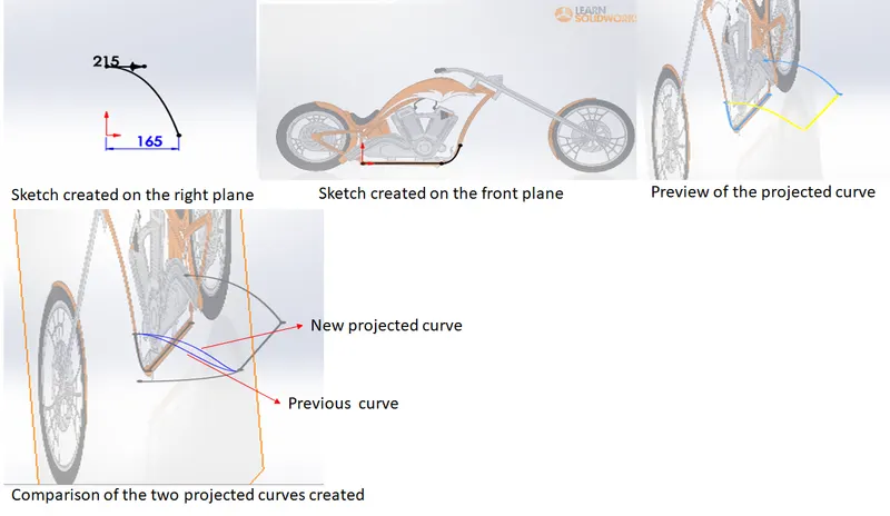
Fig 5.11.3: the new projected curve created and its comparison with the older one.
Then a profile was created as shown in the below figure and was amde into a sweep as shown in the below figure.
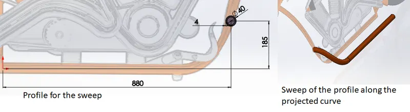
Fig 5.11.4: The sweep created for the lower member of the chassis.
This created sweep was then made into a mirror for getting the other side of the chassis lower member. Attached figure shows the process.
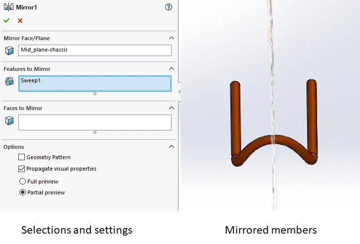
Fig 5.11.5: The mirror created for the lower member
While creating the mirror, for selecting entities the bodies to mirror option gives a choice of whether to merge the results or not unlike the features to mirror option.
Next the process for getting the back plate of the chassis was started. A sketch was made on the right plane and it was extruded as shown in the below figure. Merge results option was used to get a single solid.
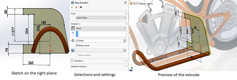
Fig 5.11.6: The extrude for the back plate.
Then a chamfer at the bottom section of the created plate was introduced to remove extra material. Distance- distance option for the chamfer was used with values set as 73 and 30 mm respectively.
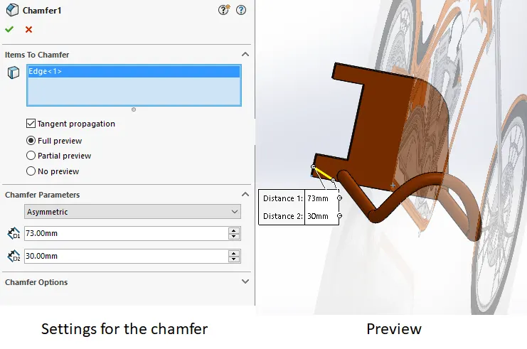
Fig 5.11.7: The chamfer applied at the bottom of the back of the plate.
Next, a cut was made in the created plate for material removal. The below figure shows details.
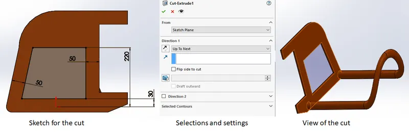
Fig 5.11.8: The deatils of the cut made in the plate.
Then two fillets as shown in the below figure were introduced for the edges of the cut made.
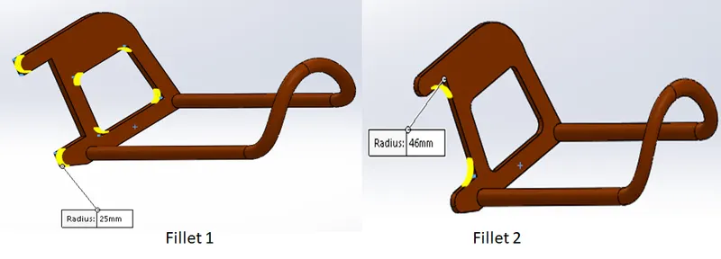
Fig 5.11.9: The fillets applied to the edges.
Next, we needed to create the back tubes of the chassis and for that a reference plane was required. The first reference for the plane was the midplane with parallel relation and for second reference the vertex as shown in the below figure was selected.
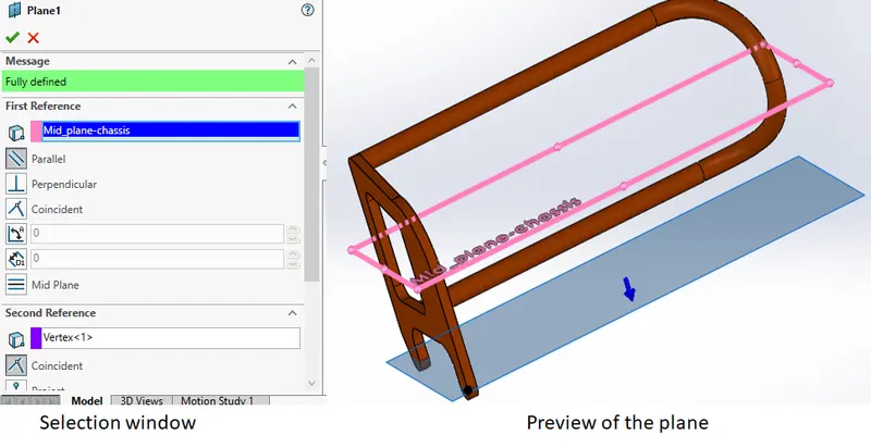
Fig 5.11.10: The details of the reference plane created
After that a sweep for the first back tube was created with the profile and guide curves as shown in the below figure.
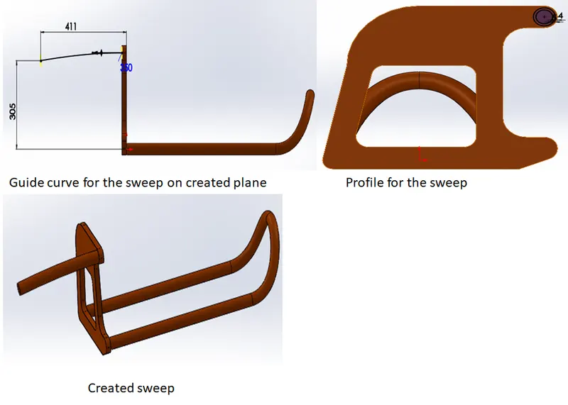
Fig 5.11.11: The sweep for first back tube of the chassis.
Then a similar sweep was created for the lower tube as shown in the below figure.
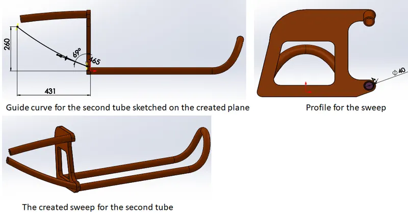
Fig 5.11.12: The second tube created at the back of plate
After that the hub for rear wheel mounting was created. A circle was sketched on the mid plane as shown in the below figure.Then midplane extrude of 44 mm was done for the created circle.
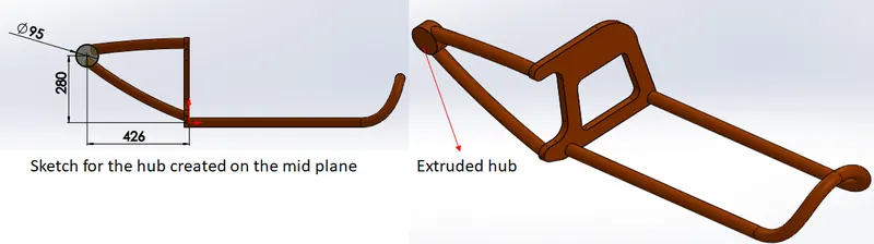
Fig 5.11.13: The extrude made for creating hub for the rear wheel.
Then 223 mm extrude of a circle was made on the inner face of the hub section created in the previous step. Below figure shows the process.
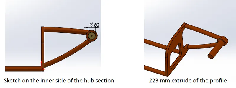
Fig 5.11.14: the created extrude for hub
A dome of 10 mm was applied on the outside face of the hub section. Then the process for making the members to join the front fork of chopper with the chassis was started. A new sketch as shown in the below figure was made on the midplane followed by a profile for creating a sweep as shown in the below figure. Pirce relation was used to make the coincidence between the guide curve and the profile.
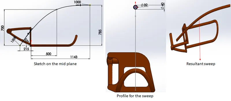
Fig 5.11.15: First member for connecting the front fork with the chassis.
Split operation, as shown in the below figure, was performed to remove extra length of the member.
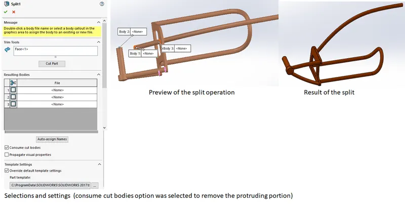
Fig 5.11.16: The split operation
After that another member for mounting the front fork was added using sweep feature. Below given figure expalins the process in detail.
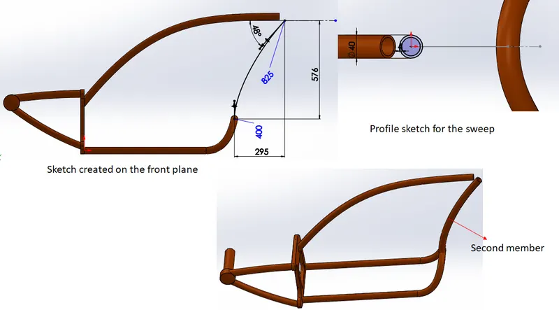
Fig 5.11.17: The sweep for the second member
Next the protruding portion of the second member created was removed using the split operation as shown in the below figure.
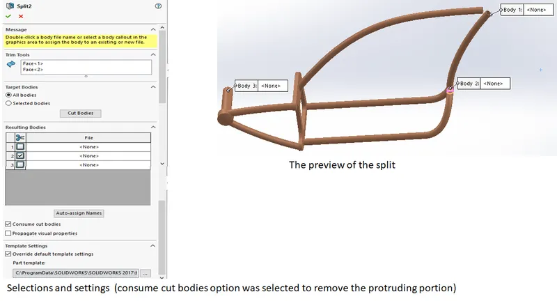
Fig 5.11.18: The split operation performed to remove the protruding portion of the member
After that all the members of the chassis created so far were combined into one using combine operation. Another revolve was added for connecting the two members created in the previous step. The attached figure shows sketch and the details of the revolve.
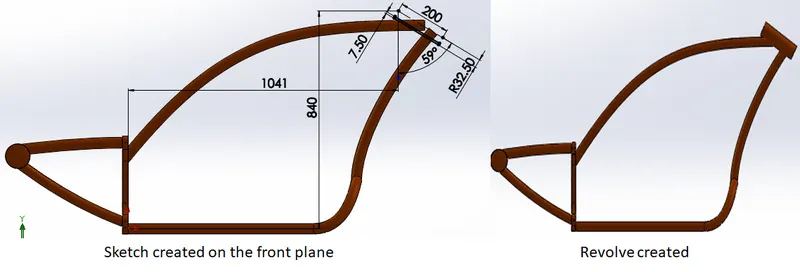
Fig 5.11.19: The revolve created for connecting the two members.
Then split was used to remove the protruding parts of the members inside the newly created revolve. The attached figure shows the details.
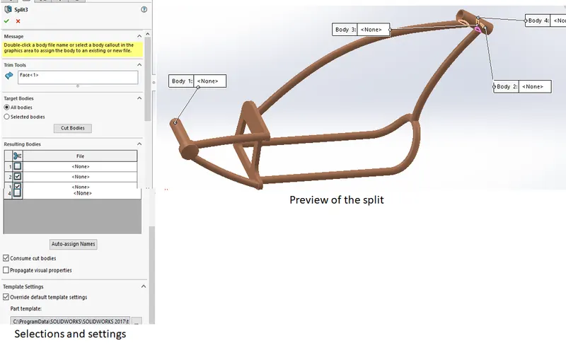
Fig 5.11.20: Split performed and the settings used
After that again a combine operation was performed to get all the bodies into a single solid.
Next a sketch was made on the front plane of the model for making the mounting plated for engine. It was extruded with up to next option in both the directions as shown in the below figure.
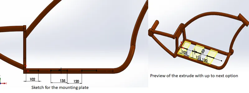
Fig 5.11.21: The sketch and the preview of the extrude made for the mounting plate for engine.
Next, a triangular bracket was needed on the lower member for mounting the pedal on it. This was made by sketching the bracket on the front plane and making an extrude with offset values to get it in the lower member as shown in the below attached figure.
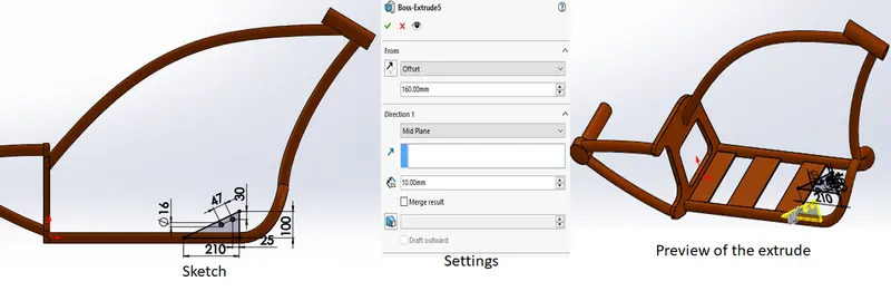
Fig 5.11.22: The sketch and the preview of the extrude made for the pedal mounting bracket
Since some of the parts of the extrude was inside the lower member so again a split was performed to remove the interfering parts.
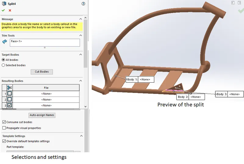
Fig 5.11.23: The split operation performed to remove the extra parts from bracket extrude.
Then two fillets as shown in the below figure were applied on the created bracket and after that mirror of the bracket was done across the front plane.
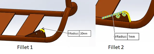
Fig 5.11.24: Fillets applied to the edges of the extrude
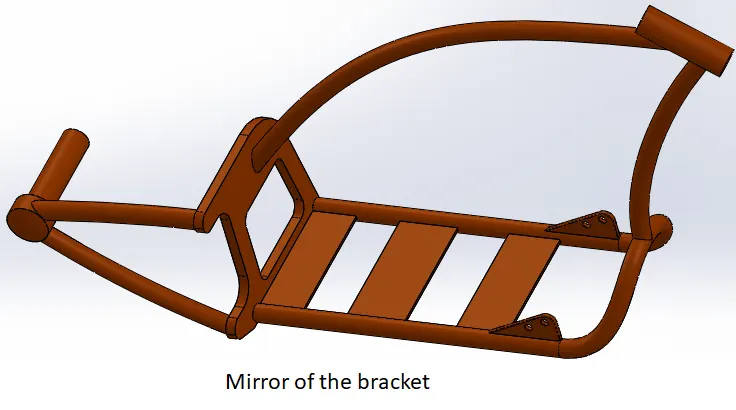
Fig 5.11.25: The mirrored bracket
After that again a combine was done to add both the newly created brackets to the chassis body. The next step was to make mounting for the kick stand with the chassis. Below figure explains the process in detail. For sketching, convert entity option was used to get the circle of intrersection of the curved tube at the front with the straight tube at the bottom.
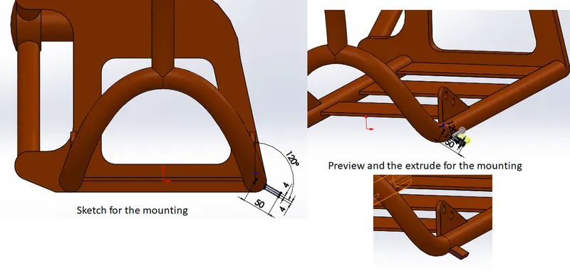
Fig 5.11.26: The extrude for mounting bracket
Then a face fillet was used on the created extrude followed by a 3 mm edge fillet as shown in the below figure. Then a hole as shown in the below figure was created on the extrude created in the previous step.
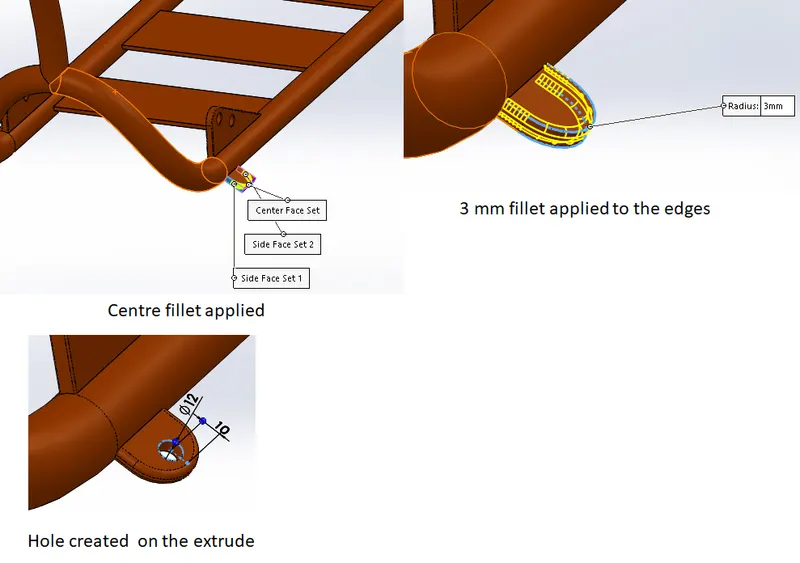
Fig 5.11.27: The applied fillets to the extrude and the hole made on the extrude.
Then a plane was created for the purpose of creating mates during assembly of the model. Attached figure shows the details of the same. It was named as the Bottom plane fuel tank for reference.
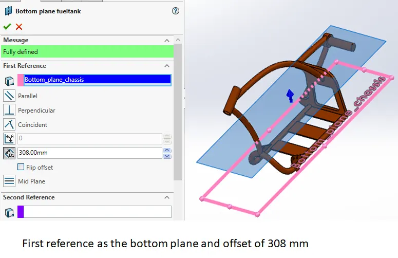
Fig 5.11.28: The plane created for assembly of the chassis and fuel tank.
At the later stage a sketch as shown in the figure was made on the back side of rear plate of the chassis. This sketch was used as a trim tool to create space for chain during assembly. Split with consume cut bodies option was used as shown in the below figure.
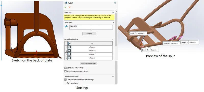
Fig 5.11.29: The sketch and the split used for creating a cut in the back plate
Finally a few fillets were used for the cut parts as shown in the below figure.
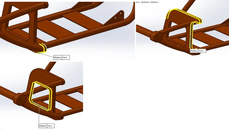
Fig 5.11.30: The fillets applied to the edges
As clear from the figures sienna was applied as appearance to all the solid bodies. After this the modelling of the Chassis was complete.
5.12 The Engine
First step in the modelling of the engine was to get the blueprint picture as the guide for creating sketches. The process of getting it was same as that of the chassis. Crank casing was created first using extrude option. The deatils are shown in the attached figure.
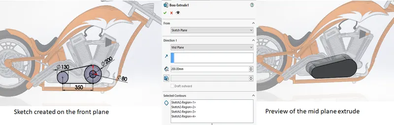
Fig 5.12.1: The sketch created and extrude made with selected contour option to extrude the entire sketch.
Next, another extrude was made with the selected contour option as shown in the below figure.
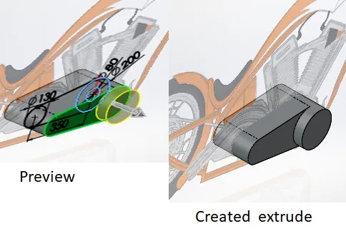
Fig 5.12.2: The preview and the extrude created using the original sketch and selecting the desired contour only with 50 mm value.
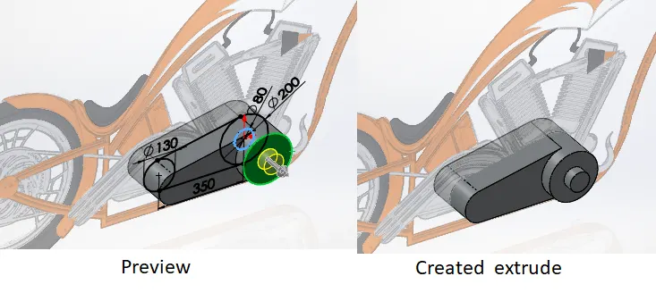
Fig 5.12.3: The preview and the extrude created using the original sketch and selecting the desired contour only with 40 mm value.
After that another sketch as shown in the below figure was created and a mid plane extrude of 150 mm was made out of it. This was made for the gear box of the engine.
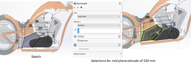
Fig 5.12.4: The sketch used and the preview of the extrude.
Then 50 mm fillet was applied to the creted extrude as shown in the below figure.
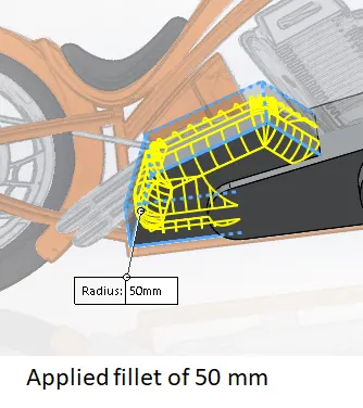
Fig 5.12.5: 50 mm fillet applied to the created extrude.
Then the smaller pulley was sketched on the right plane and this sketch was made into a revolve as shown in the below attached figure.
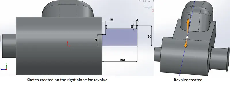
Fig 5.12.6: The sketch and revolve for smaller pulley
After that a plane was created for making sketch to get a revolve for the bigger pulley. The details of the plane are shown in the attached figure.
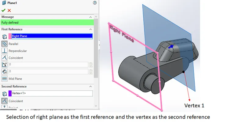
Fig 5.12.7: The plane created for making sketch of revolve used in bigger pulley.
Sketch for the revolve as shown in the attached figure was made and it was made into a 360 revolve.
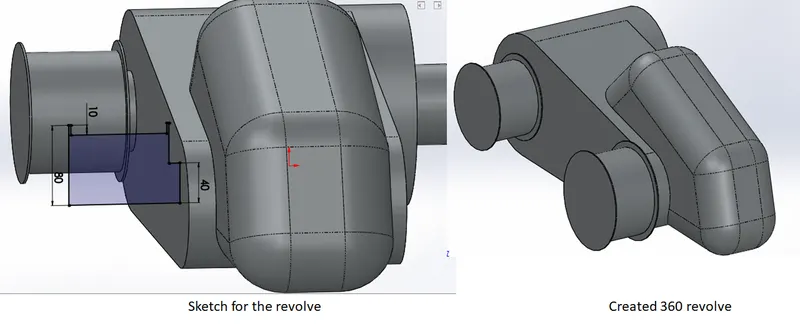
Fig 5.12.8: The prpcess of getting bigger pulley of the gearbox
Then the process for getting steps on the pulley was started. A rectangle was sketched on the back face of the smaller pulley and it was made into an extrude as shown in the below figure. While making the sketch, the edges were brought into the sketch using convert entity and then converting into construction geometry.
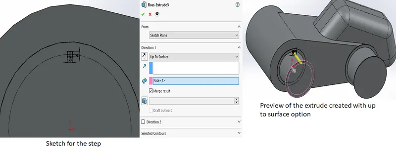
Fig 5.12.9: extrude made for getting a step on the bigger pulley.
The created step was made into a circular pattern with 40 instances to get it around the entire pulley.
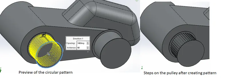
Fig 5.12.10: The process of getting steps along the pulley face
Similar process was followed for getting the steps on the other pulley. Attached figure shows the process.
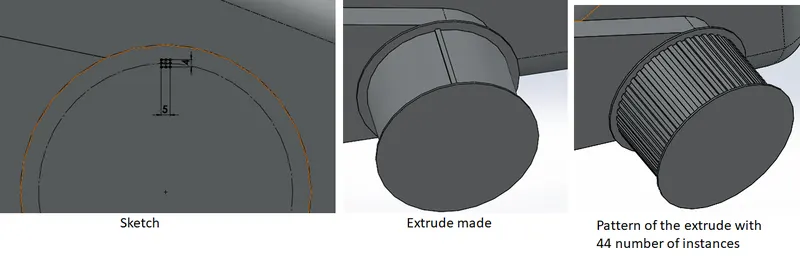
Fig 5.12.11: The steps around the bigger pulley
Then 10 mm dome was created on the outside face of the pulleys.
The next step was to make a cut on the faces of the pulleys for material removal and decoration. The sketch was made using circular sketch pattern of a 10 mm hole for 12 instances and converting the edge for getting the inner circle. Below attached figure shows the process in detail.
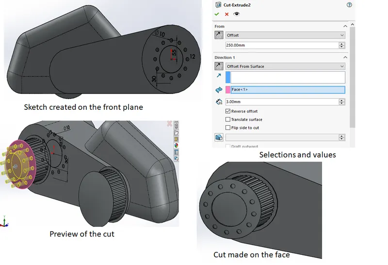
Fig 5.12.12: The process of getting cut on the outer face of the pulley.
For making the cut 250 mm offset from the sketch plane i.e. the front plane and a cut depth of 3 mm was used as clear from the above figure.
A similar cut was made for the smaller pulley as well.
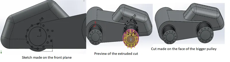
Fig 5.12.13: The process of getting cut on the bigger pulley.
Then a chamfer and fillet was applied as shown in the below figure.
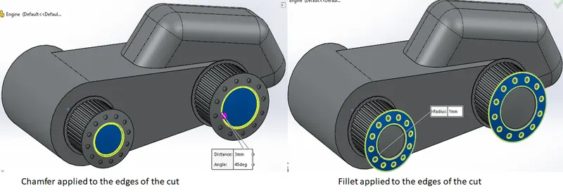
Fig 5.12.14: The chamfer and fillet applied on the edges of the cut.
Next, the process for getting the starter motor was started. An extrude for the motor in the shape of a cylinder was made.
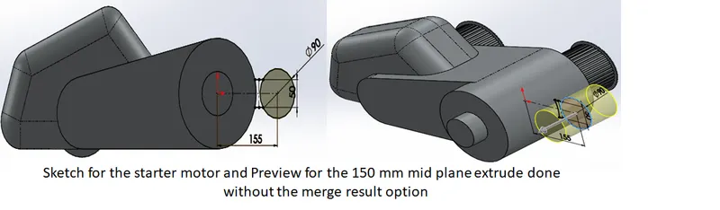
Fig 5.12.15: Starter motor sketch and extrude made for it
Next another extrude out of the same sketch was made for the connecting portion of the starter motor. The below attached figure shows the process of making the extrude.
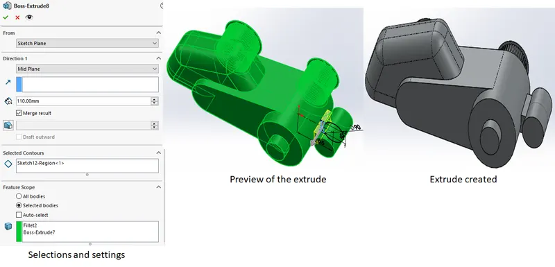
Fig 5.12.15: Extrude made for the connector of the starter motor.
After that the process of making the combustion cylinder and the fins was started. A reference sketch as shown in the below figure was made on the front plane. This line was later used for sketching the cylinder cover.
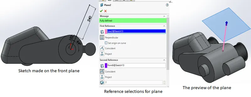
Fig 5.12.16: The sketch and the plane created for making the sketch and extrude for the cylinder cover.
Then a sketch for the cylinder cover extrude was made on the created plane.
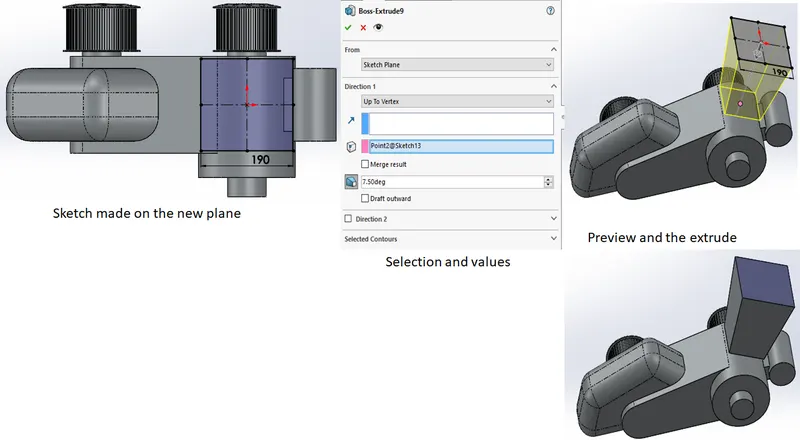
Fig 5.12.17: Sketch and extrude for the cylinder cover.
Next the connecting portion of the cylinder cover and the crank case was made from the lower part of the previous extrude. For it, a sketch was made on the lower part as shown in the below figure.
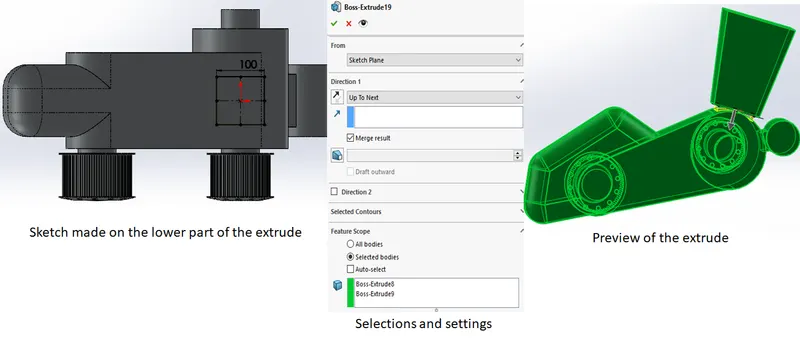
Fig 5.12.18: The sketch and preview of extrude made for connecting the cylinder cover and the crank case.
Next a staraight extrude out of the original sketch was made for upper portion of the cylinder cover. The details are shown in the attached figure.
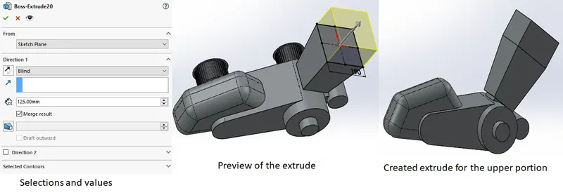
Fig 5.12.19: The preview and created extrude for the upper portion of the cylinder cover.
Next, a chamfer was applied on the created extrude to get its desired shape. Distance - distance mode was used with a value of 90 and 15 respectively. Below attached figure shows the details.
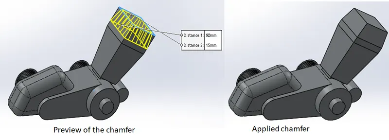
Fig 5.12.20: The chamfer applied in distance-distance mode to the upper part of the cylinder cover.
After that a 15 mm fillet was applied to the edges as shown in the figure.
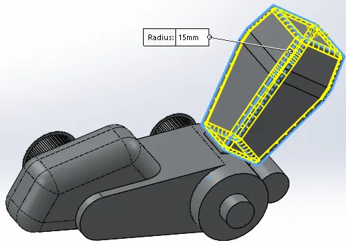
Fig 5.12.21: 15 mm fillet applied to the edges of the cylinder cover extrude.
Then extruded cut was used to get fins on the cylinder cover body. Sketch was made on the plane used for generating the cylinder cover profile and extrude cut with offest value as shown in the below figure was used to get the fin.
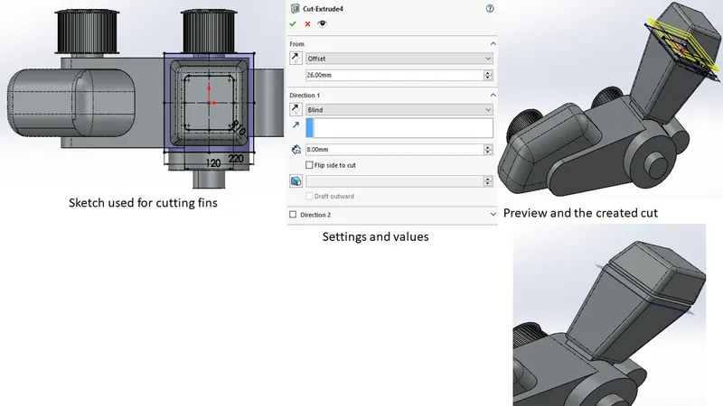
Fig 5.12.22: The process of getting cut for modelling fin.
This cut was made into a linear pattern with 16 mm equal spacing and 14 number of instances along the sketch shown in the figure 5.13.16. Attached figure explains the details.
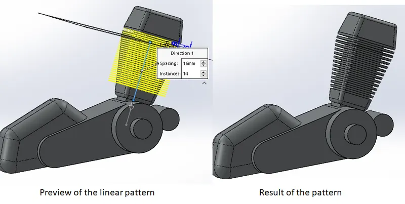
Fig 5.12.22: Linear pattern of the cut made for fins.
Next four sets of fillets were applied to various edges as shown in the below figure.
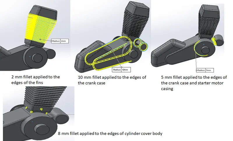
Fig 5.12.23: Fillets applied to various parts of the engine.
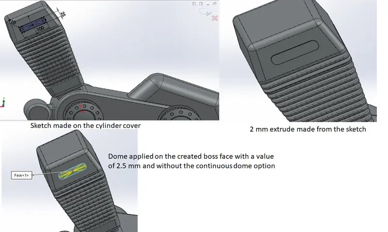
Fig 5.12.24: The dome applied to the created boss face.
Then the created fetaure was mirrored across the front plane to get it on the back face as well.
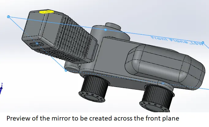
Fig 5.12.25: The mirror of the created boss across the front plane created on the cylinder cover.
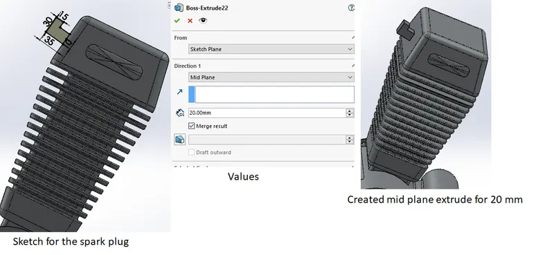
Fig 5.12.26: The process for getting the spark plug lid connector using extrude.
Next two fillets were applied as shown in the below figure.
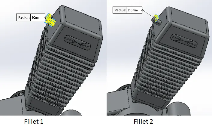
Fig 5.12.27: The fillets applied to the spark plug lid extrude
Next, a split operation was used to remove the protruding portion of the cylinder cover in the crank case. below given figure explains the details.
After that the cylinder was mirrored across the right plane for getting the second cylinder of the engine. Attached figure shows the details.
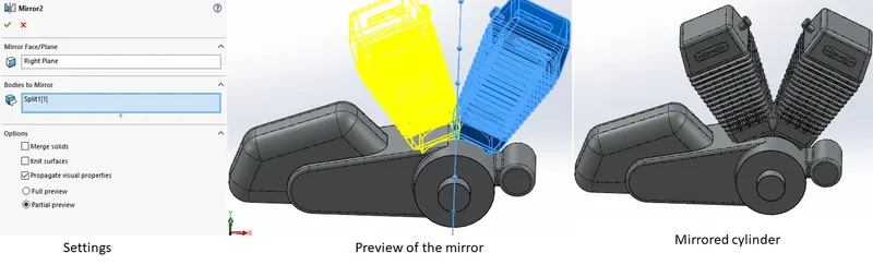
Fig 5.12.28: The mirror done for getting the second cylinder.
Then two fillets as shown in the below figure were applied to the model.
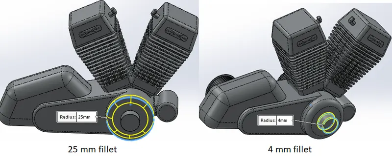
Fig 5.12.29: The fillets applied to crank case edges.
After that four mounting legs were made below the engine block
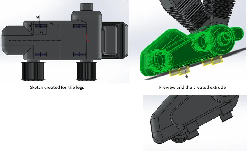
Fig 5.12.30: The mounting legs created in the engine block using 50 mm extrude.
After that another extrude below the created legs was made as shown in the below figure.
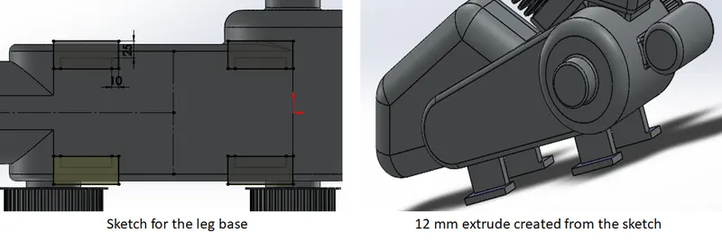
Fig 5.12.31: The mounting leg base created in the engine block using 12 mm extrude.
After that two fillets were added to the model as shown in the below figure
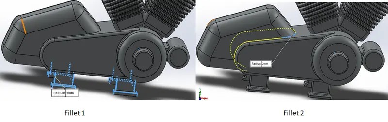
Fig 5.12.32 the applied fillets.
The next feature added to the model was extrude for making the sprocket. Attached figure shows the process. A 90 mm extrude for modelling the shaft of sprocket was made and on the outer face of the
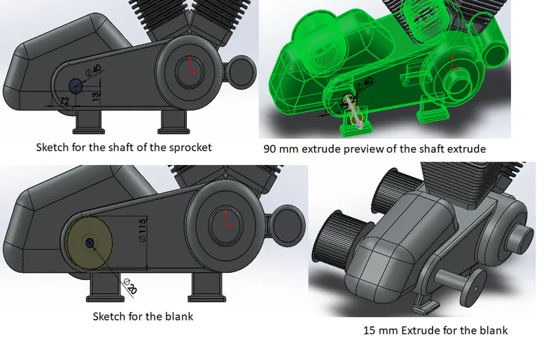
Fig 5.12.33 the process of making the shaft and blank of the sprocket.
Then the process of making teeth on the blank was started and first a chamfer as shown in the below figure was created. Next a sketch was made for creating a tooth of the sprocket. 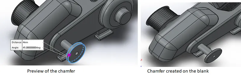
Fig 5.12.34: The chamfer applied to the blank of the sprocket.
After that a sketch was made to create the first cut for teeth for the sprocket. After creating the cut a fillet of 2.2 mm was applied to the edges as shown in the below figure.
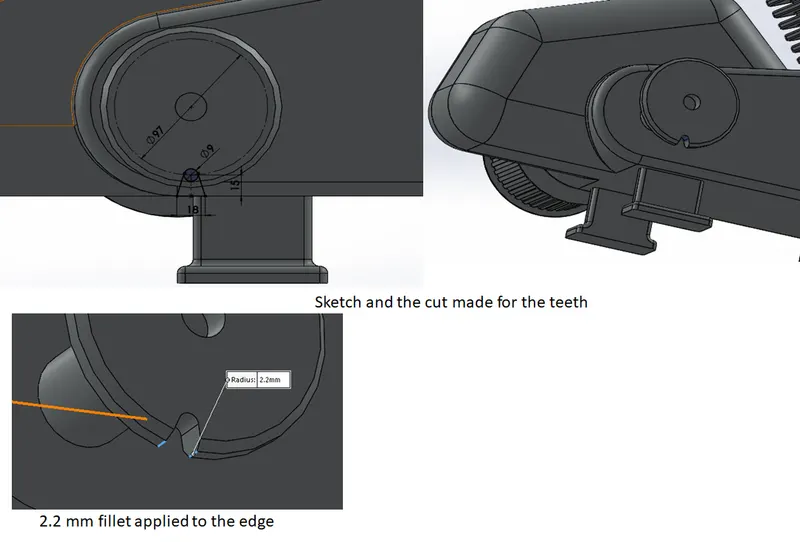
Fig 5.12.35: The cut and the fillet applied to the edges.
Then circular pattern of the cut was made with 21 instances to get all the teeth along the periphery of blank.
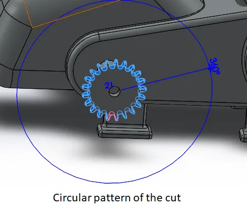
Fig 5.12.36: The pattern of the created cut.
After that taper shape of the shaft was achieved with the help of chamfers of distance-distance and distance-angle options as shown in the below figure.
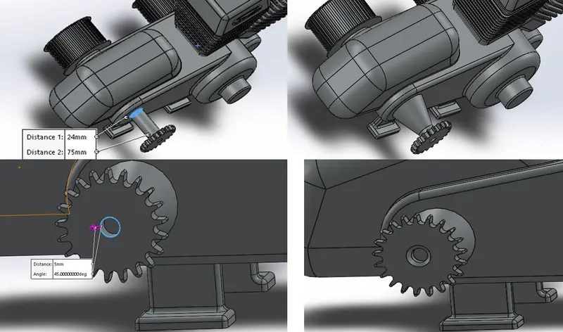
Fig 5.12.37: The chamfer created on the shaft and the hole on the blank.
The next part to be added to the model was intake manifold for the cylinders. Sweep of a profile as shown in the below figure was made to get the fitst part which was mirrored later on to get the part for the second cylinder. The profile was sketched on the right plane while the path was sketched on the front plane of the model.
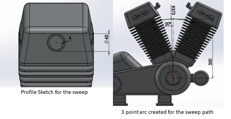
Fig 5.12.38: the sketches made for creating the intake manifold.
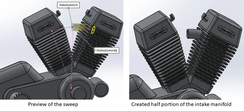
Fig 5.12.39: The sweep created for the manifold.
The remaining half portion of the manifold was created using the mirror tool as shown in the below attached figure. After that the two parts were combined using combine tool.
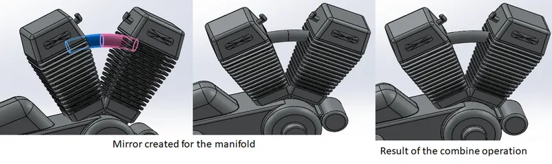
Fig 5.12.39: The mirror created for the manifold.
Next, the extension of manifold pipe was to be modelled, for it a reference plane was created as shown in the below attached figure.
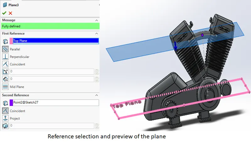
Fig 5.12.40: The reference plane created for the manifold extension.
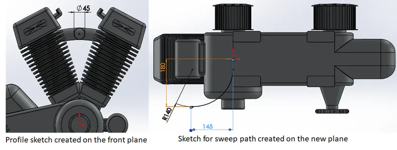
Then sweep was created with the above two sketches for manifold extension.
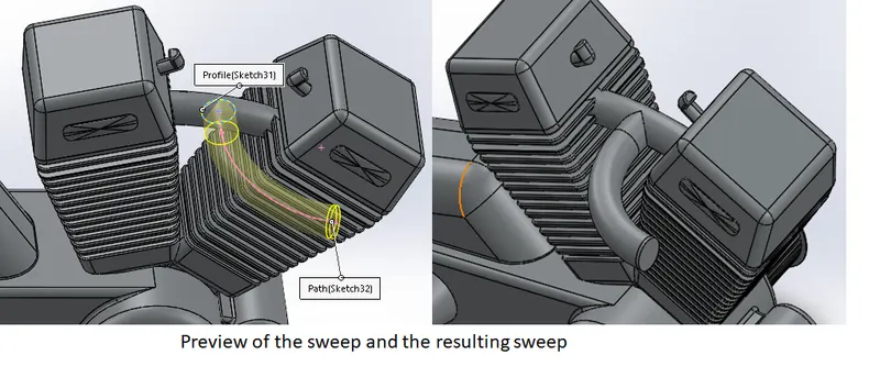
Fig 5.12.41: The manifold extension created using sweep feature.
The next part to be added to the model was the air filter of the intake unit. This was done using the revolve feature. Attached figure shows the process.
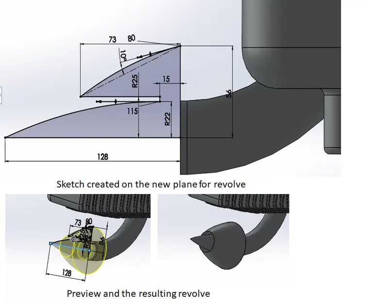
Fig 5.12.42: The revolve created for the air filter.
Note: R22 and R25 dimensions appearing in the above sketch are the radii for the revolves.
After that material removal from the created filter cone was done. For it a sketch was made on the top plane of the model as shown in the attached figure.
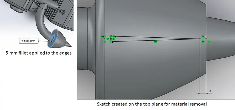
Fig 5.12.43: The fillet applied and the sketch created on the top plane of the model.
Then extruded cut was used with offset from surface option to get the cut. details are sjown in the attached figure. after making the cut, a circular pattern of geometry type was used with 30 number if instances ro get the cuts along the surface.
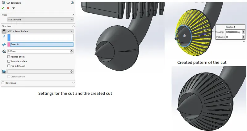
Fig 5.12.44: the cut and its pattern made on the conical face of the air filter.
Then the process of getting two mufflers for the combustion cylinders was started. Peojected curves were used extensively to get the desired shape of the mufflers. Attached figure shows the process in detail.
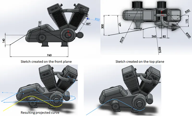
Fig 5.12.45: The lower part of the sweep path for the first muffler.
In a similar fashion the upper part of the sweep path was created. The attached figure shows the process in detail.
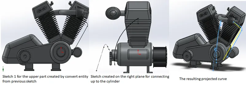
Fig 5.12.46: The upper part of the sweep path obtained using projected curve.
The sweep path was created in two parts so that there does not remain any overlapping portion of sketches lying in two didderent planes (here top and front planes).
Then the two curves created were made into a single curve using the composite curve option as shown in the attached figure.
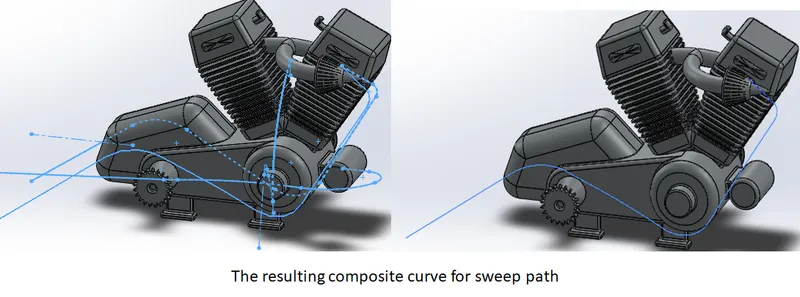
Fig 5.12.47: The composite curve created for the sweep path.
Next a plane was created for sketching the profile of the sweep for first muffler.
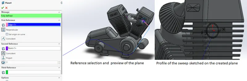
Fig 5.12.48: the sweep profile created for the muffler
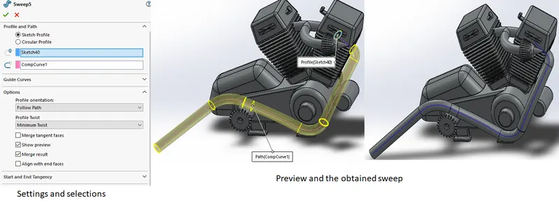
Fig 5.12.49: The sweep obtained for the first muffler.
A similar process was followed to get the sweep path for the second muffler. Attached figure shows the process in detail.
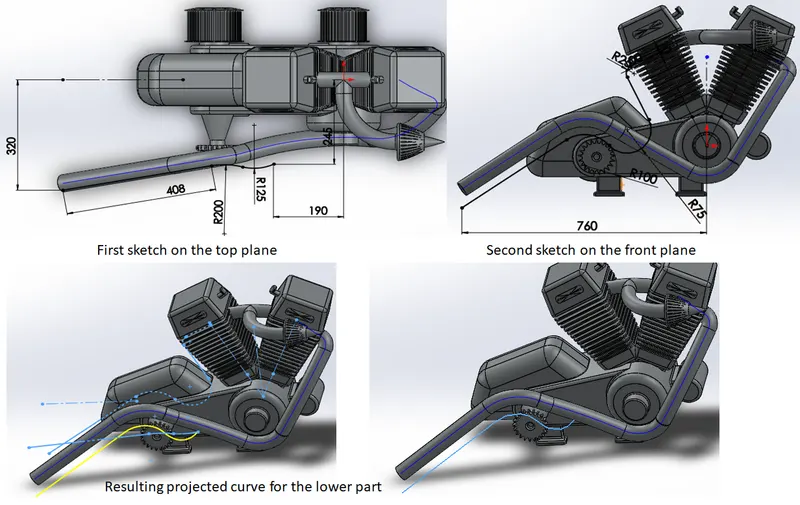
Fig 5.12.50: The lower part of the sweep path for the second muffler
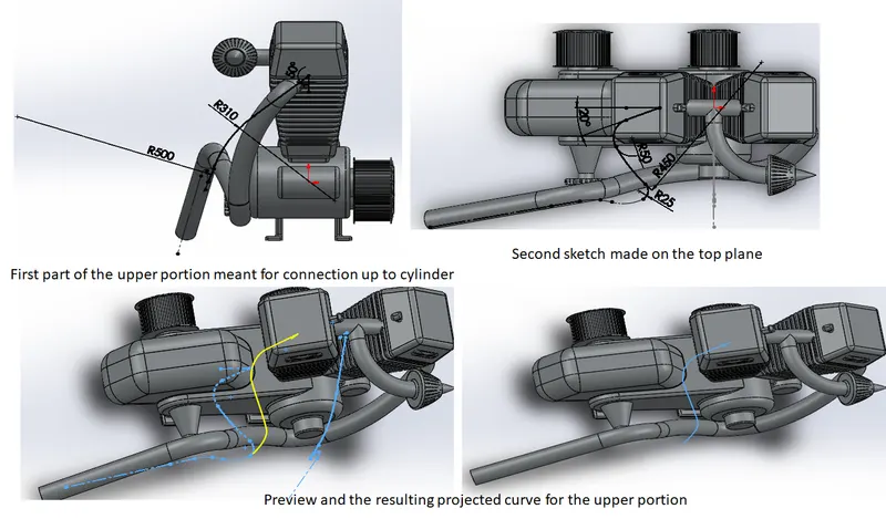
Fig 5.12.51: The upper portion of the sweep path for second muffler.
After that the two obtained projected curves were made into a single curve using the composite curve option.
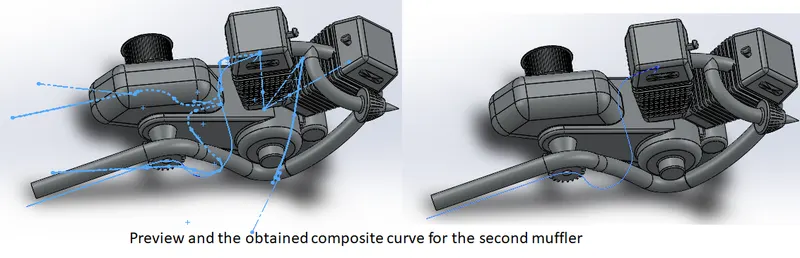
Fig 5.12.52: The composite curve to be used as the sweep path for the scond muffler.
Then a plane was created for sketching the profile of the second muffler sweep. Attached figure shows the plane and the profile.
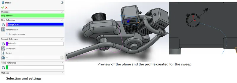
Fig 5.12.53: the plane and sweep profile for the second muffler sweep
Next, sweep was made to get the second muffler. Attached figure shows details for the same.
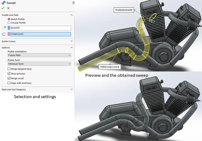
Fig 5.12.54: The sweep obtained for the second muffler.
Then the extended tail portion of the mufflers needed to be cut for styling. This was achieved using the split tool as shown in the attached figure.
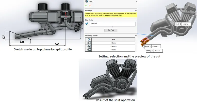
Fig 5.12.55: The split operation performed to get the cut along the tail of the mufflers.
Finally the cable connecting the spark plugs of the cylinders was modelled. Sweep feature was used to get the two connecting cables.
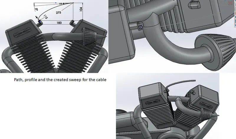
Fig 5.12.56: The cable created for the spark plug.
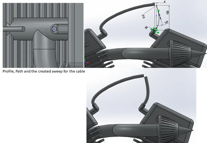
Fig 5.12.57: The second cable created for the spark plug.
Finally chrome was applied as material to the model and modelling of the engine was complete after this step.
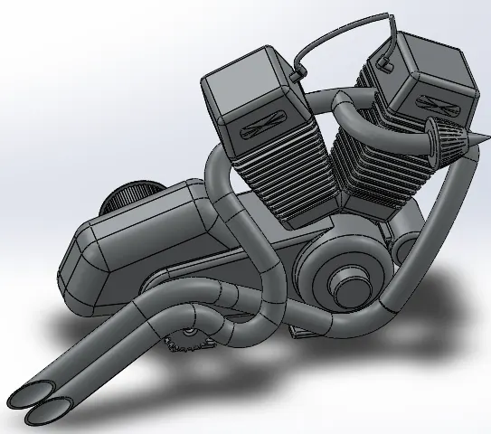
Fig 5.12.58: The modelled engine
5.13 The Fuel Tank
Fuel tank was mostly designed as surface component and features of surface modelling were used extensively. The first step was to get a blueprint of the chopper for reference during the process. Then a sketch, as shown in the below figure, was created on the front plane and a plane was created on its front end as shown in the figure.
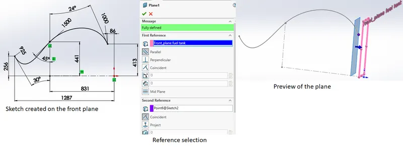
Fig 5.13.1: The sketch created as sweep path on the front plane and plane created for the profile sketch
Then the profile as shown in the below figure was created on the created plane. After that a surface sweep as shown in the figure was created.
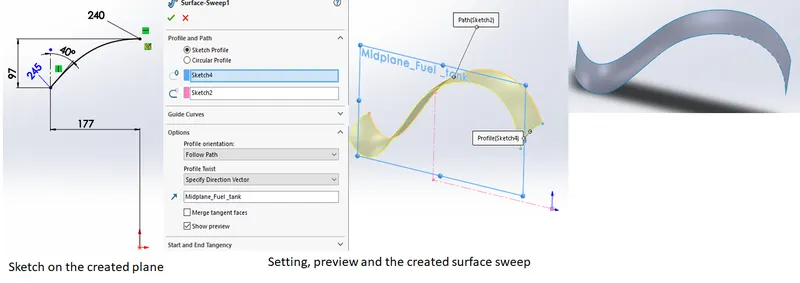
Fig 5.13.2: Surface sweep created
The created sweep was trimmed as shown in the attached figure, for getting the desired shape.
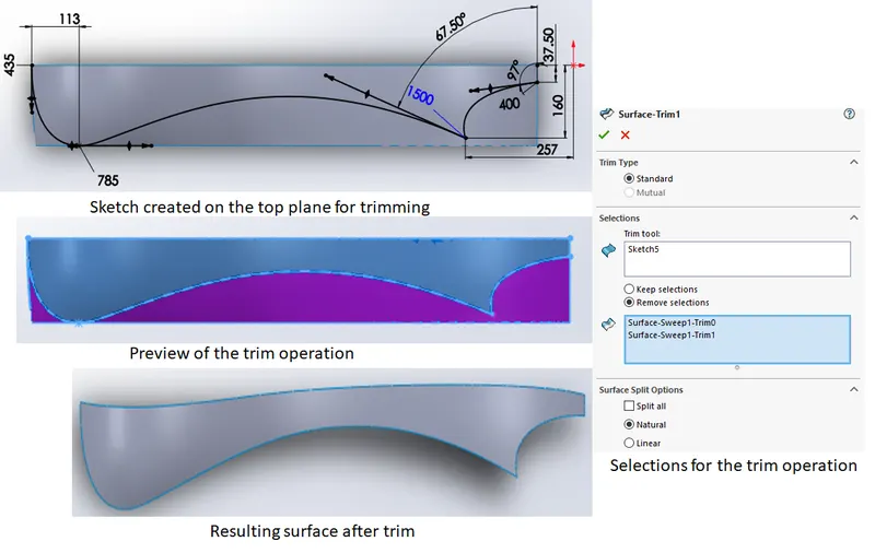
Fig 5.13.3: The trim operation performed on the created sweep.
Then the process for getting the lower portion of the fuel tank was started. A plane was created with the references as shown in the attached figure. This plane would be used later on.
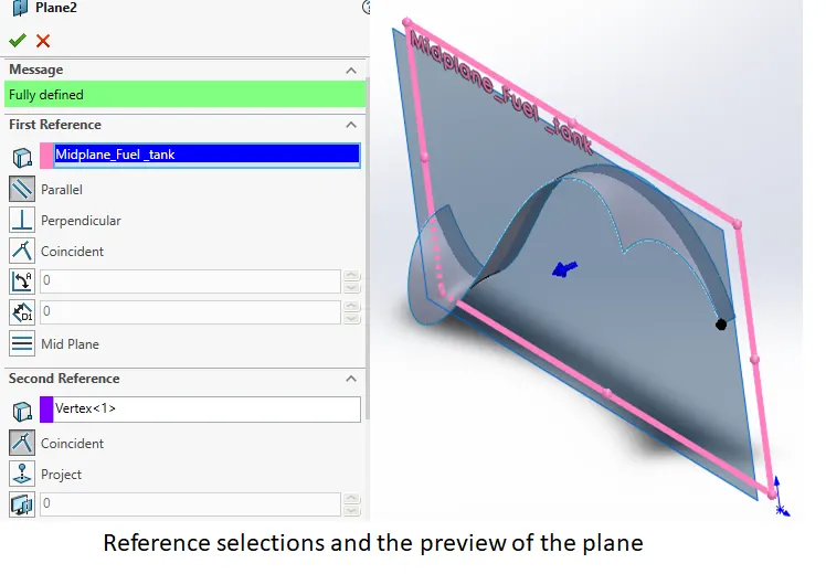
Fig 5.13.4: the plane created which would be used later on.
Then a projected curve was created for modelling the loft surface for enclosing the created surface.
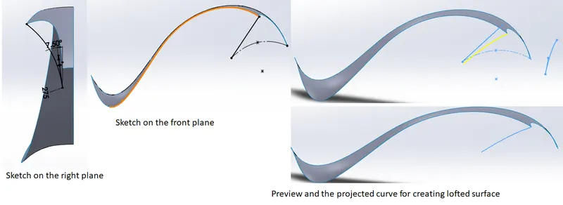
Fig 5.13.5: the created projected curve for getting lofted surface
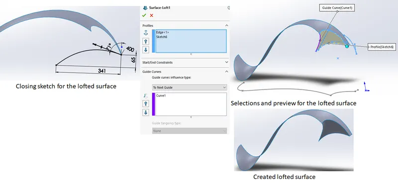
Fig 5.13.6: The lofted surface created for closing front side
Then a reference plane was created for later use. The references were front plane and the mid point of first sketch as shown in the attached figure.
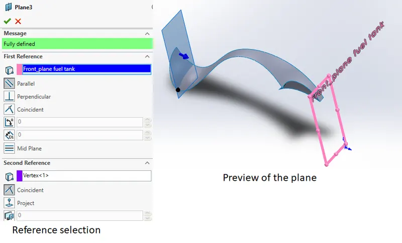
Fig 5.13.7: Plane creation
After that a projected curve was made to model the side of the tank. Details for the curves is shown in the attached figure.
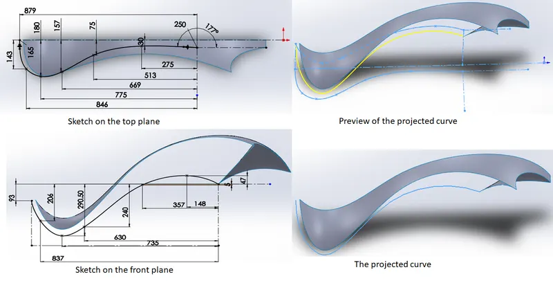
Fig 5.13.8: The projected curve made for lower portion modelling.
Then boundary surface was used to get the lower portion of the tank as shown in the attached figure.
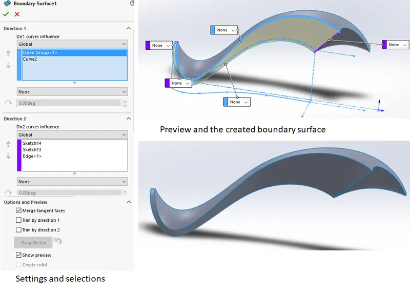
Fig 5.13.9: The created boundary surface
This step completed modelling of half of the tank which was made into a mirror about the mid plane to get the other half. 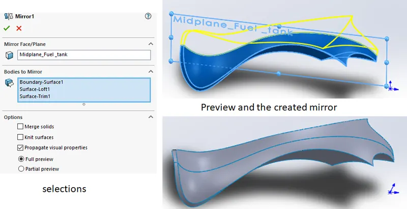
Fig 5.13.10: The mirror created for modelling the second half of the tank
Then knit surface operation was used to combine all the suefaces into a single body.
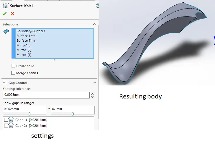
Fig 5.13.11: The Knit operation performed on the model.
Next the seat was to be modelled on the tank body. This was done by projecting a sketch on the surface using the split line tool. Details are shown in the attached figure.
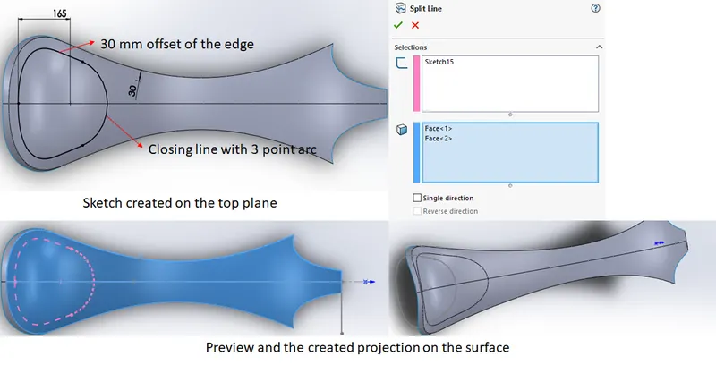
Fig 5.13.12: The split line tool used to get the sketch on the tank.
After that Surface extrude was used to extrude the created sketch. This operation removes original faces and knits the resulting surfaces together.
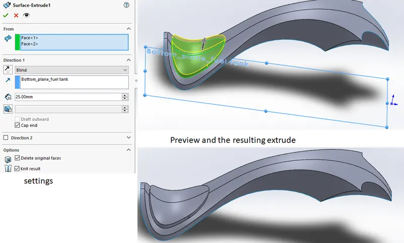
Fig 5.13.13: the surface extrude created for seat.
A 20 mm fillet as shown in the attached figure was applied to the edge as shown in the below figure.
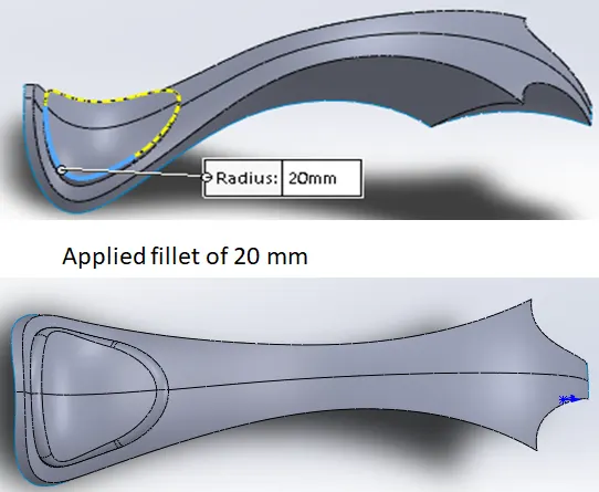
fig 5.13.14: The 20 mm fillet applied to the edge of seat
Then the bottom of tank was filled in two steps using the boundary surface as shown in the attached figure.
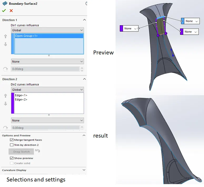
Fig 5.13.15:First boundary sirface created to fill the bottom of the tank
Next, the remaining portion of the belly was filled using loft surface as it was having curved edges.
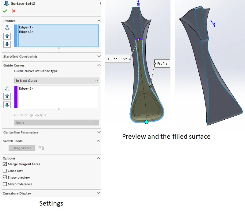
Fig 5.13.16: The loft surface created to fill the belly.
Then Knit surface was used to combine all the created surfaces into one. Also, the body was made into a solid by selecting the 'create solid' option in the menu.
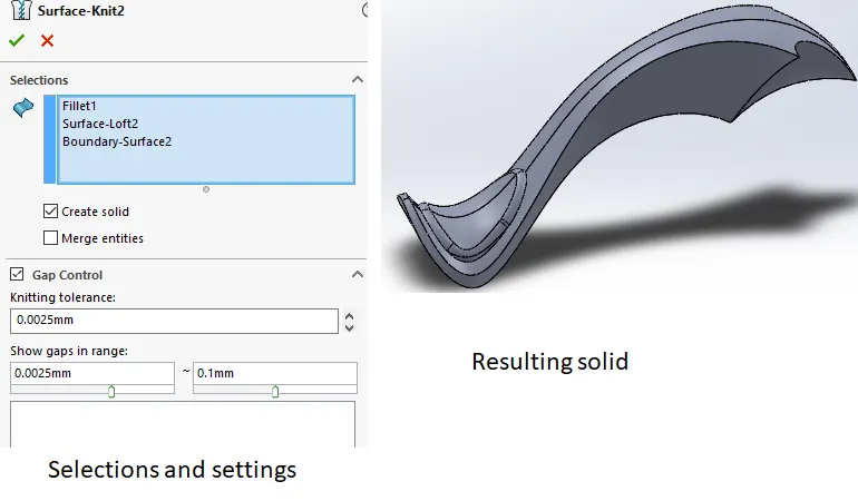
Fig 5.13.17: The knit surface operation used to combine all the surfaces and create a solid out of them.
Then 5 mm fillets as shown in the attached figure were applied to the edges of the model.
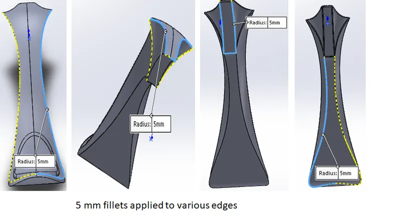
Fig 5.13.18: The fillets applied to the edges of the model.
Next, a swept cut was made under the belly using a profile and a guide curve as shown in the attached figure.
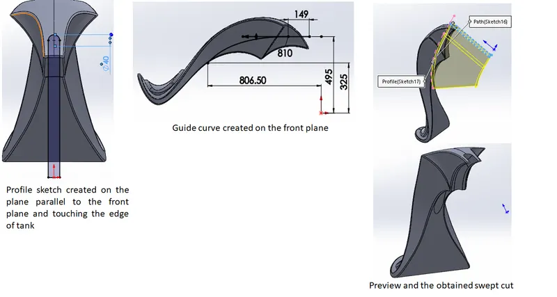
Fig 5.13.19: The swept cut used for material removal from under the belly.
Then 2 mm fillet was applied to the created edges and after that shell command with 3 mm thickness was used.
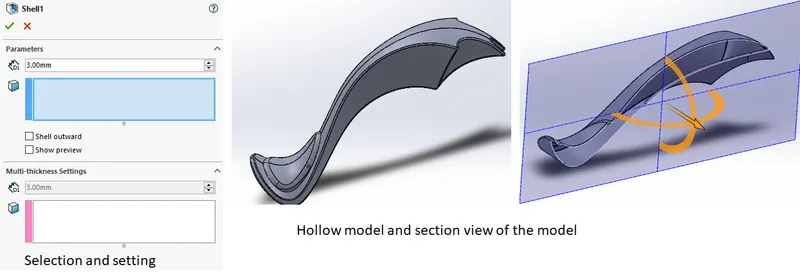
Fig 5.13.20: the shell command used
Finally sienna appearance was applied to the model and grey cotton was applied to the seat as shown in the attached figure.
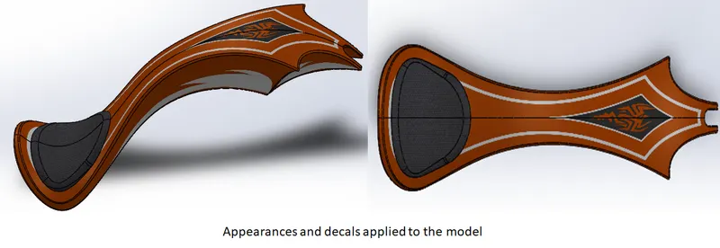
Fig 5.13.21: The appearances and decals applied on the fuel tank.
With this step the modelling of fuel tank was complete.
6. Assembly of the Chopper
A new assembly was created in the solidworks and the first component to be imported was the chassis. it was placed at the origin by simply selecting the ok button without positioning it.
The next component inserted to the assembly was the engine.
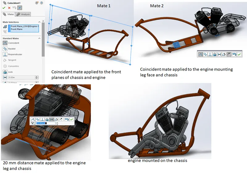
Fig 6.1: Mounting of engine on the chassis
The next component inserted to the assembly was the pedal. Three mates were applied to the part as shown in the attached figure to fully constrain its rotation and translation.
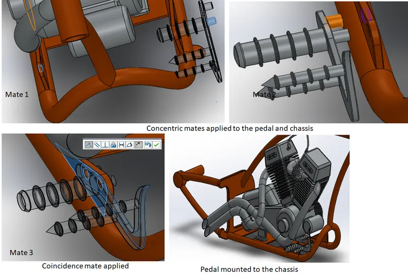
Fig 6.2: The mounting of pedal to the chassis
Next, a mirrored component of the pedal was created for the other side of the bike. This was done inside of the assembly itself and LH was added to it as suffix for identification purpose. the attached figure shows details for the same.
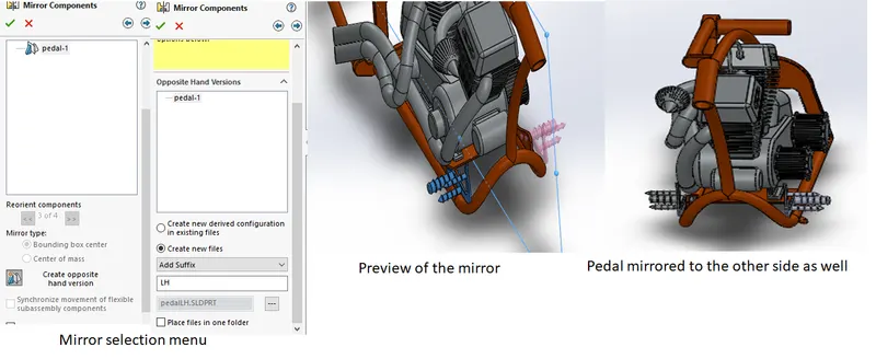
Fig 6.3: The mirror of the pedal obtained
The next component inserted to the assembly was the kick stand. Three mates as shown in the attached figure were applied to it. The limit angle mate available under the advanced mate options was used to permit the rotation of the kickstand.
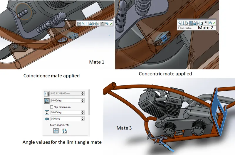
Fig 6.4: the mates applied to the kickstand
The next part added to the assembly was the transmission belt. Width, concentric and angle mates were applied to position it properly in the assembly. The attached figure shows details for the same.
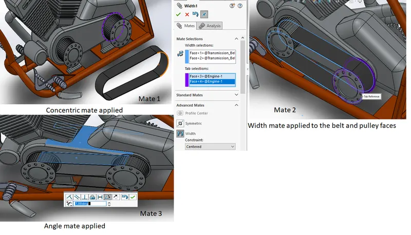
Fig 6.5: The mates apllied to the belt.
The next part added to the assembly was the oil tank. Three mates were applied to it as shown in the attached figure.
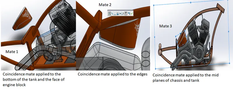
Fig 6.6: The mates applied to the oil tank
Next component added to the assembly was the rear fender. Mates applied to fix it are shown in the attached figure.
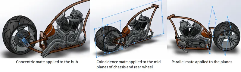
Fig 6.7: The mates applied to fix the rear wheel with the frame.
The next component added to the assembly was the rear fender. The mates applied to fux it to the assembly are shown in the attached figure.
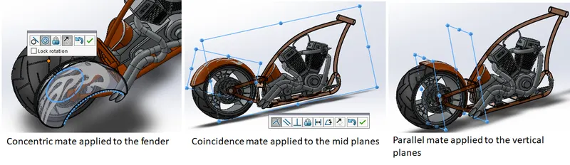
Fig 6.8: The mates applied to attach rear fender to the assembly
After that the chain was added to the assembly. The mates applied to position the chain properly are shown in the attached figure.
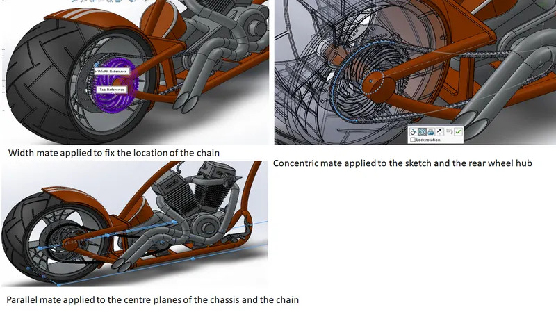
Fig 6.9: The mates applied to the chain
The next component inserted into the assembly was the fuel tank. Mates applied to position it are shown in the attached figure.
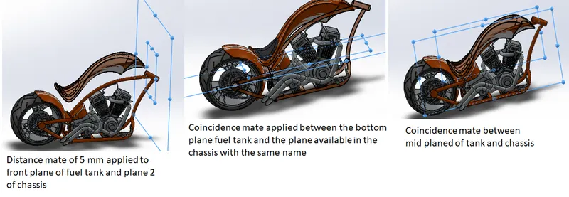
Fig 6.10: The mates applied to the fuel tank
After that front fork was added to the assembly. Attached figure shows the mates applied to the front fork and chassis.
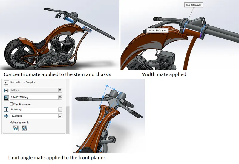
Fig 6.11: The mates applied to constrain the front fork
The next part added to the assembly was the front wheel. A plane in the middle of the front fork was created to mate the front wheel properly. The details are shown in the attached figure.
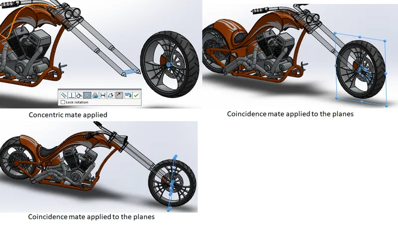
Fig 6.12: Mates applied to the front wheel
The final component inserted into the assembly was the front fender. Mates applied to constrain it are shown in the attached figure.
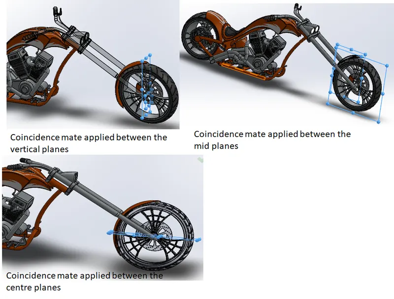
Fig 6013: Mates applied to constrain the front fender.
With this step the assembly of the chopper was complete. The part and assembly files are available to view through the Google Drive link: Abhishek_Kr_Chopper_Assembly
7. Rendering of the chopper
First of all a tangent relation was added between the tyres and the top plane to make the bike appearing touching the ground. A similar mate was applied between the kickstand and the top plane to make the bike appear being parked.
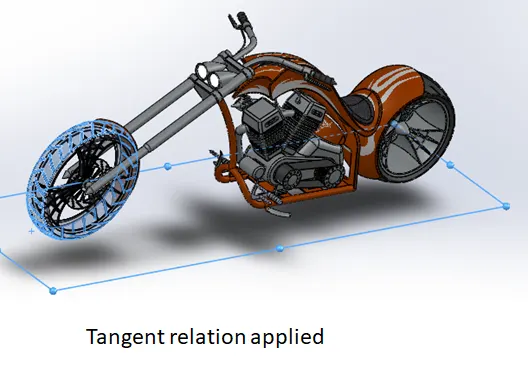
Fig 7.1: The tangent relation applied to front wheel and the top plane.
Then rendering was done in the Solidworks Visualise. With the limited processing power available, higher number of passes could not be applied. Some of the rendered images are attached below.
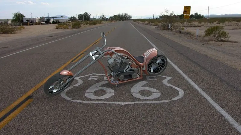
Fig 7.2: The rendered image using back plate in visualize.
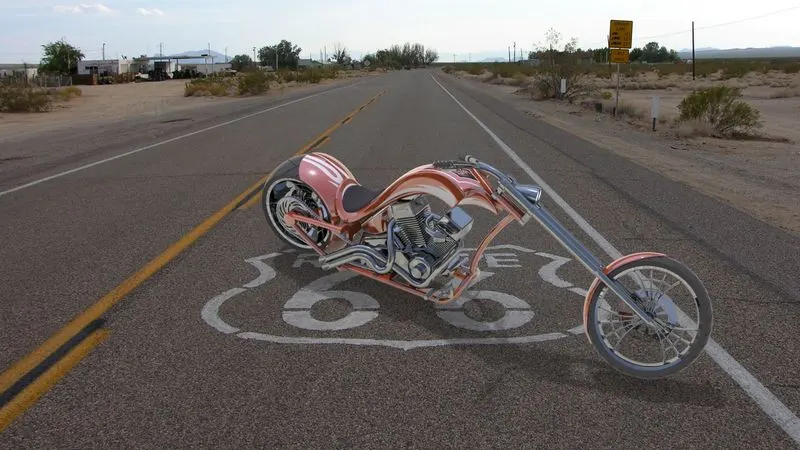
Fig 7.3: second rendered image

Fig 7.4: Rendered image with a different background
8. Conclusion
Working on this project was a wonderful tour to the resources available in the Solidworks software. This project enabled me to explore the variours designing options, methodologies and difference between varoius methods of solid and surface modelling. A good amount of exposure was made to the rendering part of modelling. Making projected curves was one of the interesting things that one can get hands on experience while working on this project. It enables the designer to get intended shape of a sweep path during modelling.
At last, I want to thank the Skil-lync team for their support and help provided in the project.