Week 6-Meshing of Hood Challenge
The meshing of hood panels using Hypermesh
1. Introduction
In this exercise, the panels of hood section used in passenger cars were meshed using Hypermesh. Step file for the hood panels was provided which consisted of four parts namely Latch reinforcement, Hinge reinforcement, outer extract and the inner extract.
All the provided components were of thicknesses in the range of 3 to 4 mm so mid surface was extracted out of all the four bodies and 2D meshing was carried out.
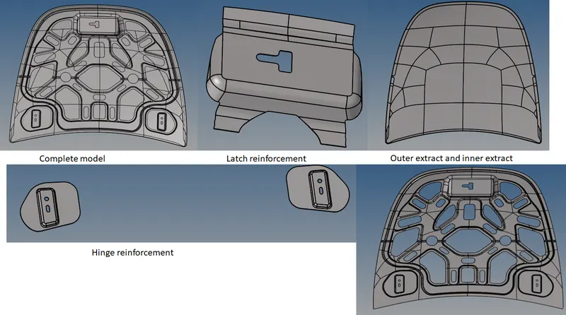
Fig 1.1: Hood panels
Meshing was carried out separately for all the four components as explained in the following sections.
2. Meshing of the Latch reinforcement
First of all, the solid bodies from the model were deleted using the delete command. Then mid surface extraction was carried out using the skin offset option available under the mid surface extraction options. Symmetrical portions of the surface were deleted and splitting, as shown in the attached figure, was carried out for convenience.
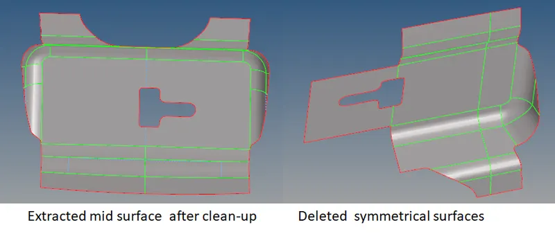
Fig 2.1: the extracted mid surface and deleted symmetric surfaces.
Then meshing was carried out with the below-attached criteria set under the criteria file setting available under the preferences settings. Mixed type of elements was used with a target size kept at 5 mm.
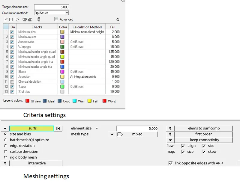
Fig 2.2: The criteria file and mesh settings
The surface was set to wireframe mode, geometry colour mode was set to 'by topo' and the element colour was set to 'by element quality'. The half portion was meshed as shown in the attached figure and reflect tool was used to reflect the remaining half.
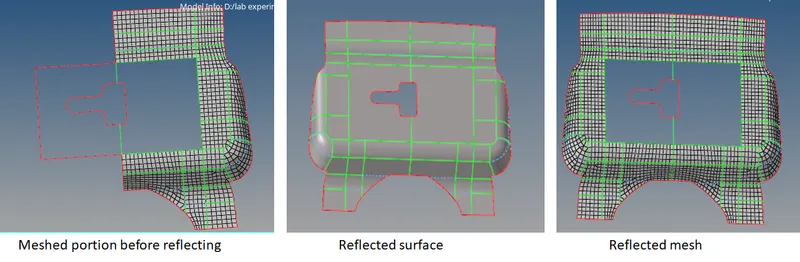
Fig 2.3: Meshing of the symmetrical portions
Finally, the remaining two surfaces of the top were meshed. While carrying out the meshing operation the topology revision scheme was set to advanced remesh for getting proper connectivity among the interface elements. The project tool was used to arrange the nodes along the feature lines.
This approach resulted in a total of 3179 elements and 2990 elements. Finally, a check for the direction of normal of the elements was made to ensure all of them were oriented properly and property was assigned to the model.
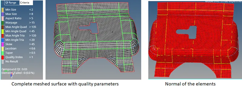
Fig 2.4: The meshed model.
3. Meshing of the Hinge reinforcement
The next part to be meshed was the hinge reinforcement. Mid surface extraction was carried out in a similar manner as done for the Latch reinforcement. One of the hinges was meshed and the elements were then reflected to get a similar mesh on the second hinge as well.
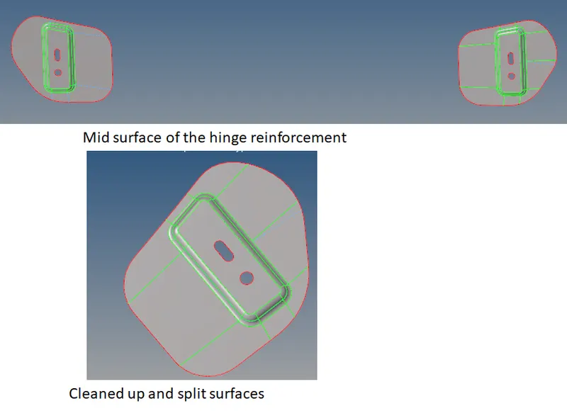
Fig 3.1: Mid surface for the meshing
Meshing around the rounded edges was done with a mix of tria elements and quads. Extensive use of the cleanup tools available in the quality index was made to ensure no failed elements were in the mesh. The 'drag tria' option was used to position two trias properly so no two of them share a common node. Node optimise and element optimise were used to make the mesh a better one.
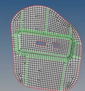
Fig 3.2: The meshed hinge reinforcement
Then the created elements were reflected using a centre node which was created using the arc centre option of the circular holes of the hinge reinforcements. The attached figure shows the details.
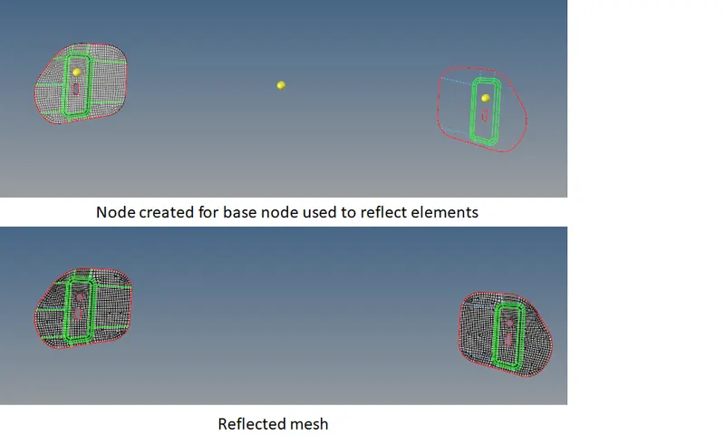
Fig 3.3: The reflected mesh
A total of 3004 nodes and 2888 elements were created using this approach.
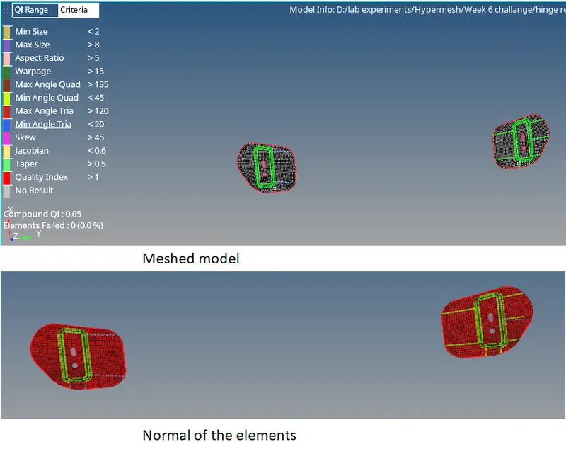
Fig 3.4: The meshed model and normal check of the elements.
4. Meshing of the outer extract
The geometry of the outer extract consisted of the nearly flat large surface with hemmings around the edges. The geometry was symmetric about the kine as shown in the attached figure.
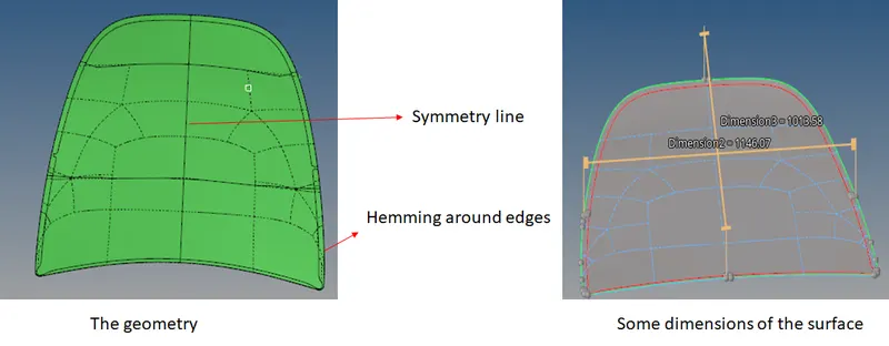
Fig 4.1: the extracted mid surface of the model.
Half portion of the model was deleted and the remaining portion was meshed after proper geometry cleanup.
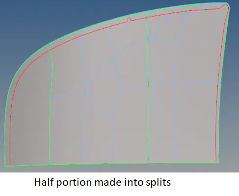
Fig 4.2: the surface used for meshing
After that meshing was carried on the split surfaces as shown in the attached figure. Care was taken in the hemmed edges so that no two trias share common nodes and there were no bad quality elements. The attached figure shows the details. This approach yielded a total of 52254 nodes and 51696 elements.
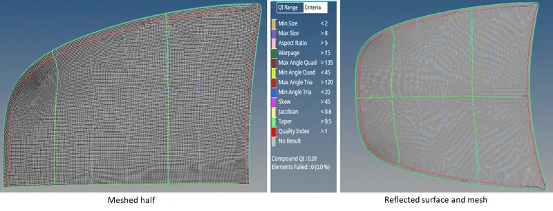
Fig 4.3: the meshed model
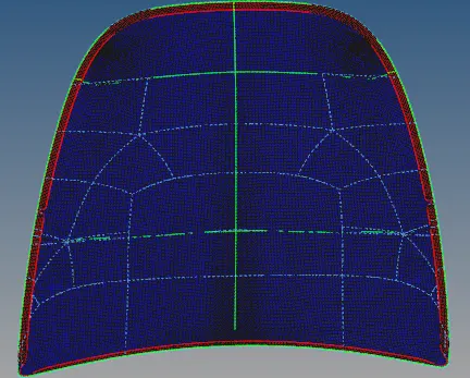
Fig 4.4: the normal of the elements of the mesh
5. Meshing of the Inner extract
This was the most difficult part of the model to mesh. It has a large number of contours and bends on the surface which needed to be captured properly. The geometry was symmetric about a vertical line. So half of it was deleted after mid surface extraction. Some of the extracted surfaces were not proper so they were made into manual offset and later on moved to the mid surface using the organise tool.
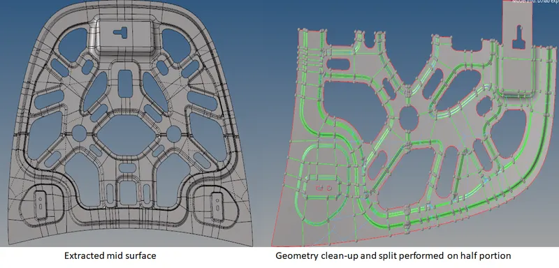
Fig 5.1: The mid surface used for meshing
After that, the meshing operation was carried out surface by surface and the topology revision was kept to advanced remesh for most of the time. In some of the areas, the topology revision was kept at 'keep mesh to avoid disturbing the created mesh and connectivity of the elements was established later on using the replace tool. Project tool was used extensively to capture the features properly by aligning the nodes along the feature lines. The attached figure shows the details.
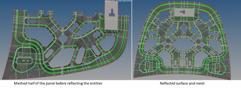
Fig 5.2: The meshed half and reflected part
After reflecting the remaining top portion was meshed. Sometimes the elements failing for warpage were corrected by translating its node in the direction of an adjacent element. The approached resulted in a total of 46342 nodes making 44911 elements.
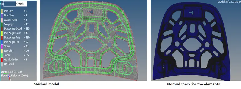
Fig 5.3: the meshed model.
6. Conclusion
This exercise enabled me to carry out 2D meshing of parts in a very practical manner. The parts provided in the exercise contained very moderate to difficult ones which require an iterative approach for getting a better mesh. Overall it was a very detailed tour of the 2D meshing in Hypermesh using Optistruct.
I am thankful to the Skyll-lync team for the support provided in the completion of this exercise.
The complete model can be viewed using the Google Drive link: Hood meshing files