Week 6 - Creating connection for Rear door
Connection Modelling for Rear door of a Passenger Car
1. Introduction
A typical car is made of almost 3000 components and each and every component is modelled when it comes to full vehicle simulation for NVH or crash simulation. The individual components from the model are meshed separately and then connected together using the appropriate type of connection. Connection modelling in itself is a gigantic task and requires a considerable amount of experience to deploy the proper connections between two parts.
In this exercise, a rear door model from a passenger car BIW was fully modelled using different types of connections available in ANSA. As an input for the exercise, a FE model was provided without CAD data. This FE model was first segregated into different property IDs (PIDs) for the convenience of connection deployment. The detailed steps are presented in the below sections.
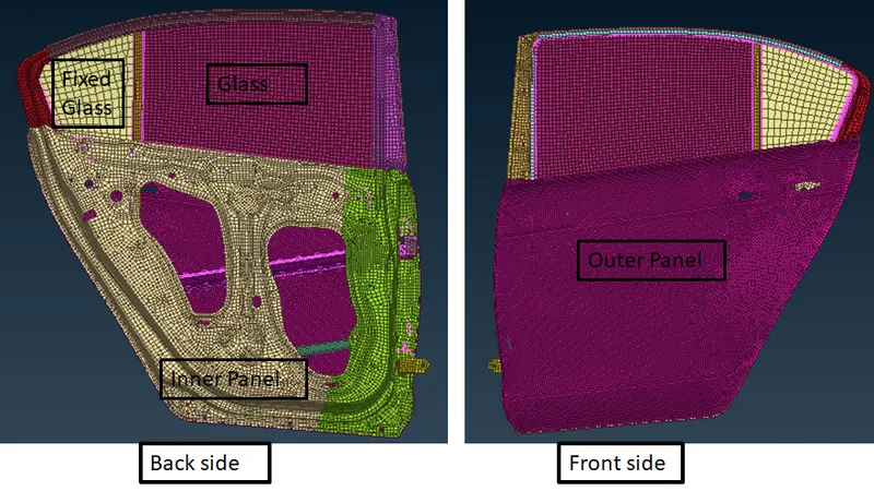
Fig 1.1: The Finite Element Model of Side Door
2. Connections in ANSA
There are various types of connections available in ANSA. Some of them are rigid connections like RBE2 elements, bolts (made of RBE2 or RBE3 elements), various types of spot welds, seam welds, elastic elements and beam elements etc. A bolted connection in FE modelling is basically represented with RBE2 and RBE3 elements. RBE2 and RBE elements are different in terms of the position of the independent and the dependent nodes. In RBE2 elements the dependent nodes are present on the periphery of the hole and the independent node is present at the centre of the hole. While in the RBE3 elements, the centre node is the dependent one while the nodes on the periphery are independent, which does not induce stiffness to the element.
For spot weld joints different types of elements can be used. Some of the elements are RBE2, CWELD, RBE2 and RBE3 elements along with hex elements etc. For Seam weld, shell elements are generally used for FE representation with various parameters like weld angle, no of steps, width etc. A special type of element called CBUSH elements is used to represent the sealing connection between the glass and frame of the window.
2.1 The Rigid connections
This connection modelling was done from the perspective of an NVH analysis using NASTRAN so all the holes that were meant for housing some mechanism, were made rigid with the help of RBE2 spider as shown in the attached image.
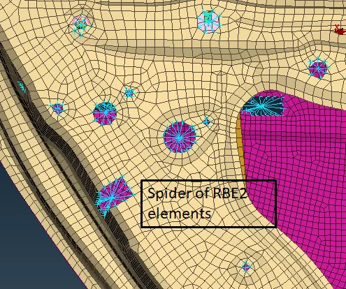
Fig 2.1.1: the rigid elements used for making the free edges a rigid one.
The nest type of connection that was used was bolt connection. A bolt connection can be directly modelled using the RBE2 or RBE3 elements or it can be deployed using the connection manager. The stem of the bolt can be modelled for a more detailed representation of the connection. Also by using the info tab, the degree of freedom for a particular element can be changed.
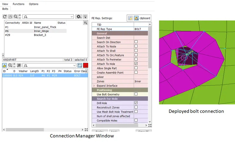
Fig 2.1.2: Details of a bolt connection
In hinge areas, the bolted connection was not made completely rigid. The stem element was allowed rotation about the Z-axis by removing 6 from the constrained motion box as shown in the attached image.
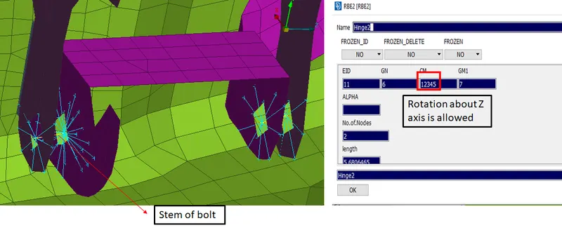
Fig 2.1.3: Modelling of bolt stem with rotation DOF
2.2 The Spot Weld connections
For long members, the spot weld connection was deployed along the edges as shown in the attached figure. For the sake of simplicity RBE2 elements were used for realising the spot welds for the reinforcement rib as shown below.
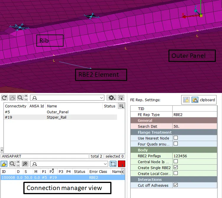
Fig 2.2.1 the spot weld with RBE2 elements.
In a similar manner, the spot weld can be created with the RBE2-Hex-RBE2 type. In this type, as the name suggests, Spider of RBE2 elements are used to model the connection between a Hexa element and the two joined plates.
2.3 The Seam Weld
Seam weld connection using shell element representation is a little bit tricky to deploy successfully. Mesh on the joining members need to be compatible for the realisation of the joint and all the parameters need to be keyed in properly. Often, the issue arises in realisation due to incorrect step length and search distances. Search distance value should always exceed the real distance between connecting parts and step length should be approximately equal to mesh size. Also, the width of the weld should be defined using an angle with a value of 45 degrees to ensure proper representation of the same.
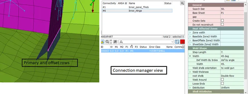
Fig 2.3.1: A seam weld deployed successfully
2.4 CBUSH elements
CBUSH elements are used to model elastic sealing joints like the one between the glass and frame of the door. Each CBUSH element needs six values of damping coefficients which are available as modelling data in the actual scenario. In our case, CBUSH elements were used along the glass edges as shown in the attached figure.
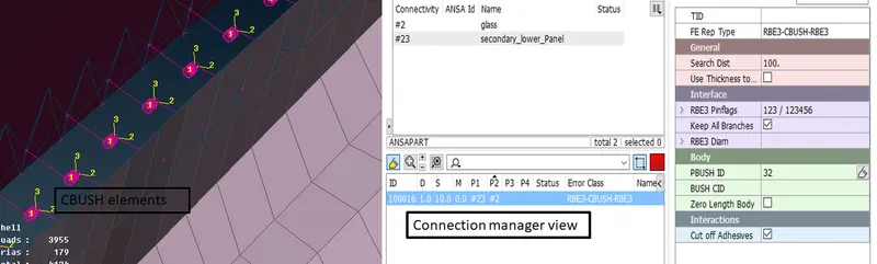
Fig 2.4.1: The RBE3-CBUSH-RBE3 connection deployed for glass and frame
Additional checks for the CBUSH elements:
All the CBUSH elements need to be oriented according to the global coordinate system. By default, they are oriented according to local coordinates which causes issues at the time of the simulation. To avoid it two modifications as shown in the attached figure were made in the CBUSH details.
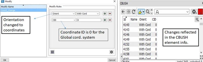
Fig 2.4.2: The changes made to the CBUSH elements
In this manner, all the connections were deployed successfully. Modal analysis can be carried out to check if all the components are connected properly or not.
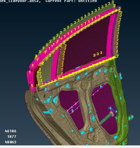
Fig 2.4.3: The completed model
Conclusion
This exercise was a detailed introduction to the connection modelling approaches in ANSA. It teaches all the basics about NVH connection modelling with different types of available options.
Thank you.