Week- 5 - Solid meshing
1. Introduction
The FE modelling of components that are above 5 mm thickness is carried out using 3D mesh. For such components usually, the mid surface can not be extracted properly as they have non-uniform features.
There are two types of 3D mesh i. e. Structured mesh and unstructured mesh. The structured mesh contains Hexa and Penta elements while the unstructured mesh contains only the tetrahedron elements.
A CAD model of a side-view mirror from a passenger vehicle was meshed with tetra elements in this exercise.
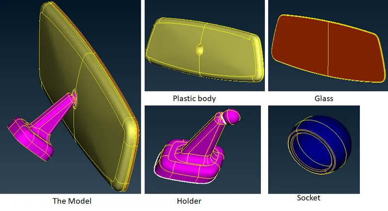
Fig 1.1: The CAD model of mirror
In an actual scenario, such components don't have much importance, they will simply be represented by a rigid link with mass. But here for the sake of learning all the components were meshed according to the following criteria:
Tria mesh: target size 1 mm, minimum size 0.5 mm and maximum size of 7 mm.
Tetra mesh: tet collapse of 0.2
The general procedure for Tetra meshing involves 2D mesh generation with tria elements on the surface of components which are then converted to Tetra elements. So the first step was getting a surface mesh with tria elements.
2. Geometry cleanup and 2D meshing
The features of the model were checked properly for any geometry constraints leading to elemental failures. Special attention was given to fillets and curvature areas and proper defeaturing by suppressing unnecessary edges and creating user splits was carried out.
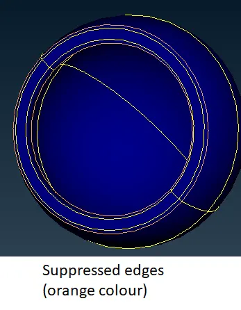
Fig 2.1: the cleanup of the socket
After that, the curved areas were meshed using ortho tria elements. They give a better feature capturing in comparison to the normal tria elements. The remaining areas were meshed with normal tria elements and appropriate quality fixing was done. The ortho tria elements take
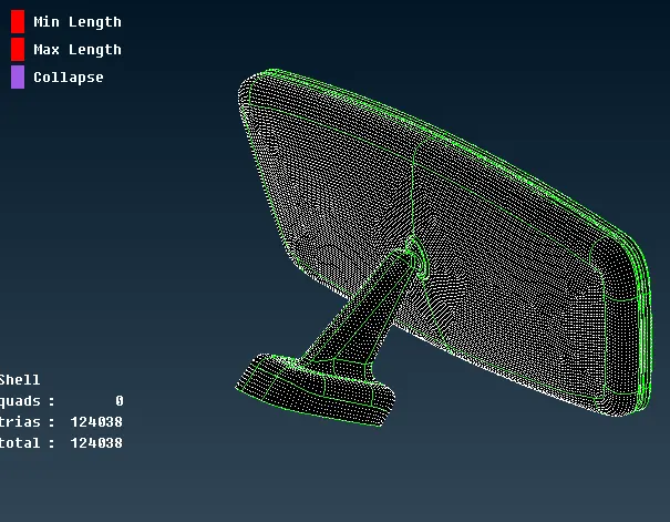
Fig 2.2: The meshed model of the mirror
3. Tetra meshing
After getting the tria mesh on all the surfaces, the next step was to create volumes out of the components. They are defined using the 'define' command from the volume tab of the volume mesh module. All the individual components were defined as a separate volume.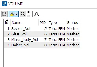
Fig 3.1: the volumes defined for each component
There are two different algorithms available in ANSA for getting tetra mesh. They are Tetra FEM and Tetra rapid. They have differences in the growth rate and the associativity between the volume and the surface mesh. In this exercise tetra, FEM was used to get the tetra elements.
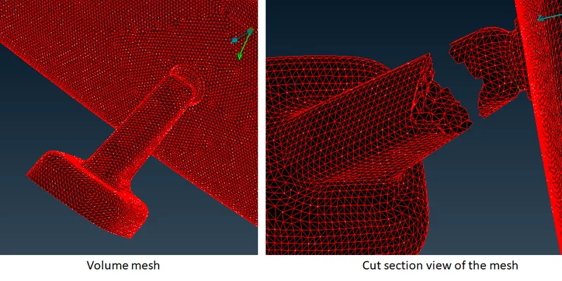
Fig 3.2: The Tetra mesh generated on the model
This approach generated a total of 993949 tetra elements.
Conclusion:
Tetra mesh generation is used for components generally above 5 mm of thickness which includes cast and mould parts. It is much easier to deploy in comparison to the shell mesh for which we need to do the mid surface modelling.
This exercise provided a good exposure to unstructured mesh generation methodology in ANSA software.
The models are attached for evaluation.
Thank you.