Assignment 1-2D Meshing Challenge
Assignment 1-2D Meshing Challenge
1. Introduction:
Shell meshing is used for components that have uniform thickness and the value of thickness is below 6 mm. It is used mostly for sheet metal parts and plastic components. The basic process includes mid surface extraction, geometry cleanup and shell meshing. Shell meshing uses 2 D elements which are assigned thickness values numerically and it saves a lot of cost in terms of computational resources needed to run the simulation.
In this exercise 3, sheet metal components were provided and it was asked to perform shell meshing with a target size of 5 mm, the minimum size of 3.5 mm and a maximum size of 7 mm.
2. The geometry
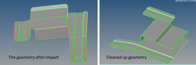
Fig 2.1: The first part
It was having missing surfaces and free edges (red edges) and duplicate surfaces which were connected as T connection (yellow edges). They were corrected by using surface edit tools like trim surface, surface generation tools like ruled surface and quick edit tools toggle, filler surface and split surface operations.
Next, the mid surface was extracted manually out of the surface using the manual offset method with an offset value of 0.91/2 was used. After that, the holes smaller than 5 mm in diameter were filled using the filler surface command available in the quick edit panel. Then user splits were created on the surfaces to achieve a better mesh flow and fillets/ bends below 3.5 mm (minimum element size) were removed by suppressing/toggling the edges so as to avoid the minimum element length failures.
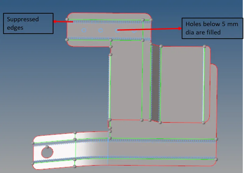
Fig 2.2: The cleaned-up mid surface of the first part
Then criteria file was updated using prescribed values as shown in the attached figure.
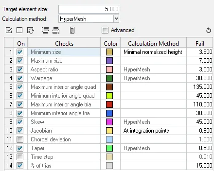
Fig 2.3: The criteria file used in the model
After that, Macro by macro meshing was done using the mixed types of elements (quads and tria elements). In the lower region where the hole is present, the element failures due to minimum length could not be avoided while attempting better feature capturing. Elements were checked for free edges and equivalence to ensure node connectivity. This approach led to a total of 397 nodes making 341 elements out of which 5 were tria elements. The cleanup tools available in the quality index menu were used extensively to avoid element failure, touching trias and rotating quads.
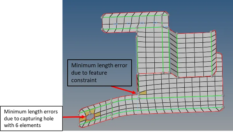
Fig 2.4: The meshed model of part 1
After that property and material were created and they were assigned to the component containing mid surface and its mesh.
2.1 Other parts
A similar approach was used for the remaining two parts. up to mid surface extraction. But in these two components, symmetry was present, so position tools were used to copy and paste elements from a meshed feature to the similar one.
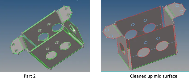
Fig 2.1.1: the geometry of part 2
Again holes below 5 mm dia were filled up and bends below 3.5 mm were not captured by suppressing one of its edges.
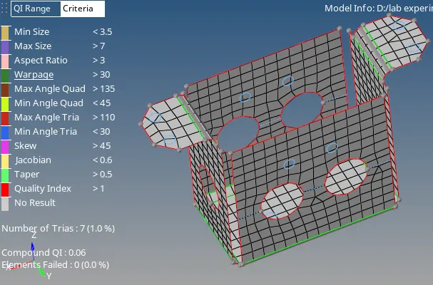
Fig 2.1.2: the meshed model of the part2
After that meshing was performed for the third part. This part contains a stamped feature in the form of a bulge which is pretty hard to capture with a minimum element length of 3.5 mm. It was simplified using a toggle command for edges and approximate capturing with a centre line was made as shown in the attached figure.
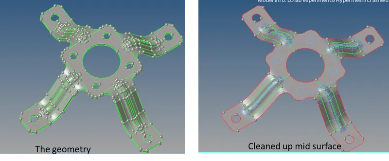
Fig 2.1.3: the geometry of part 2
The position tool was used to copy and paste the mesh from one leg to the remaining three legs. The holes on the central portion were filled up for simplifying the geometry.
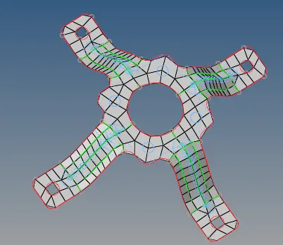
Fig 2.1.4: The meshed model of part 3
The models are attached for evaluation in the asset section.