Week 12:Project 2-Meshing of Rear Wheel Holder challenge
Mesh Generation on the Trunk model using Hypermesh
1. Introduction
In this exercise, a trunk portion of an Automobile BIW was meshed using Hypermesh software. BIW stands for the 'body in white', referring to the automobile sheet metal welded structure or body shell. The most general materials are steel and aluminium alloys used for the fabrication of the body shell. All the other parts like the door, bumper and dashboard are mounted on it.
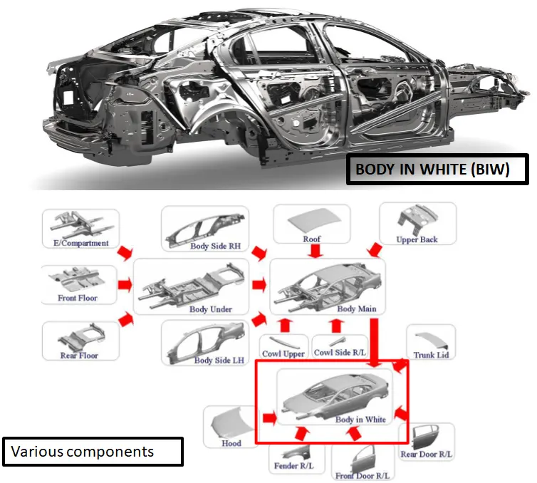
Fig 1.1: Schematic of BIW
The extracted mid surface of the trunk model was provided as a part of this challenge. The first step was the geometry clean up of the surfaces to get rid of all the extra features which may alter the mesh quality.
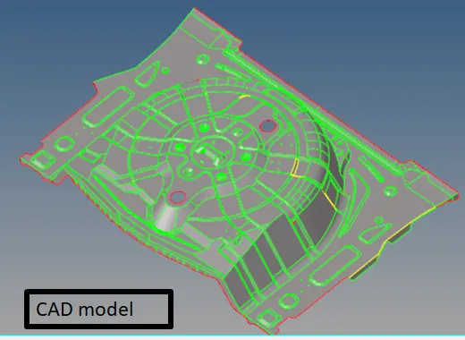
Fig 1.2: The mid surface of the trunk portion of BIW
This model contained a lot of features that needed to be corrected or simplified in order to get proper mesh quality. Some of them are shown in the below-attached figure.
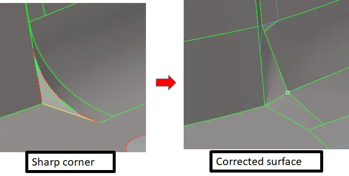
Fig 1.3: The removal of sharp corners.
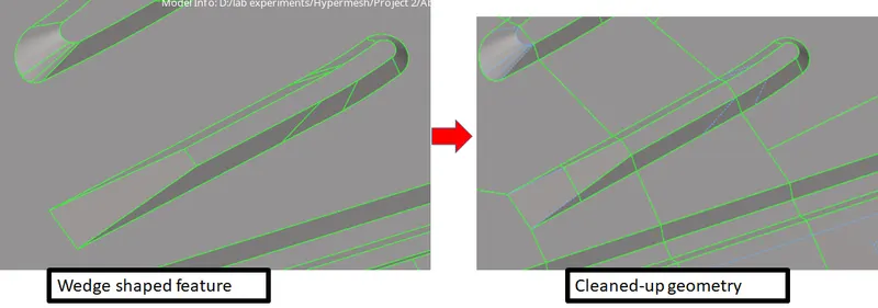
Fig 1.4: The geometry cleanup of feature
Some small features, in the form of small buttons or spheres, were present in the model. It was not possible to mesh them with mentioned quality criteria for the challenge so, they were removed and the surface was patched as shown in the below-attached figure.
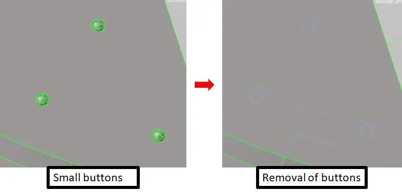
Fig 1.5: the removal of small features
The next step was mesh generation on the surface. Since it was a component with thickness less than 6 mm, 2D or shell mesh was used.
2. Mesh Generation
The quality criteria file for the mesh generation is shown in the below figure.
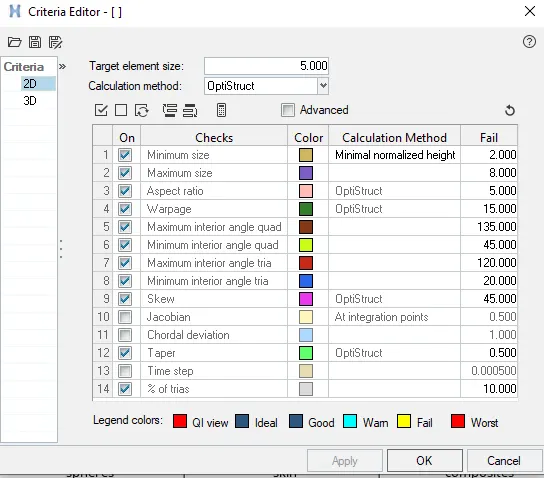
Fig 2.1: the criteria file for mesh generation
Element type was selected as mixed along with a target size of 5mm for the mesh generation. Proper splits were created during the cleanup so that meshing could be carried out in surface by surface manner keeping a check on the quality. In some of the regions like the one shown below, presence of sharp corner or pointed features were leading to warpage, minimum angle tria and minimum length errors. This was overcome by allowing a slight deviation of nodes from the feature lines as shown in the figure.
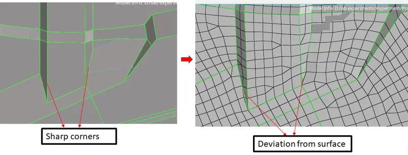
Fig 2.2: The capturing of sharp edges
The other option for mesh generation, in such an area, would be to toggle or suppress one of the feature lines and allowing the capture of features from adjacent surfaces as a single surface. This option was also tried but, it created problems in achieving proper mesh flow along with high warpage in the range of 25-30 degrees.
A similar approach was adopted for other such regions where two feature lines were meeting at a very narrow angle.
There was an edge on either side with a height of 1.95 mm which is less than the minimum element length. So, there were two options, either to allow a little bit of node deviation in the vertical direction to get a value greater than 2 mm(minimum length allowed) or to allow the elements to fail for the minimum. Since minimum length failures can be accepted in feature constrained areas like this one, the elements were allowed to fail as shown in the figure.
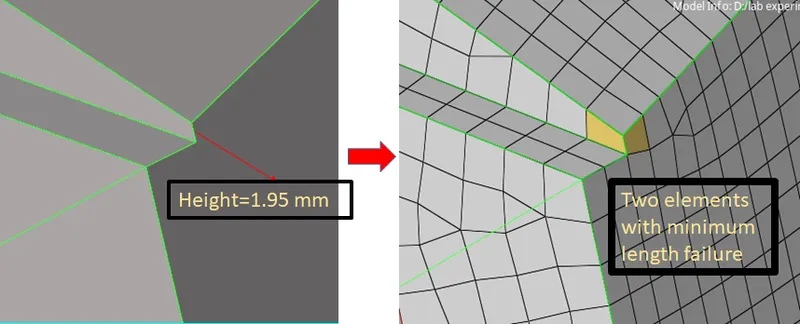
Fig 2.3: Minimum element length failures allowed in the mesh
This approach generated a total of 43886 elements made of 43706 nodes.
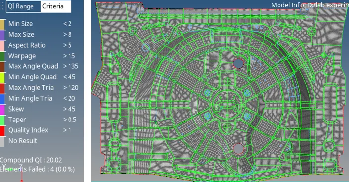
Fig 2.4: The mesh generated on the surface
The last step was material and property assignment to the model. A thickness value of 1 mm was assigned along with steel as the material for the model.
The model is attached for evaluation.
Thank you.