Week-7 Head Impact
Child Head Impact Test on a Car Hood and calculation of HIC using LS-Dyna software
1. Problem Statement: In this project, a children's head form model is provided. You are supposed to replicate a scenario where this head form will impact a car bonnet. The bonnet should be considered as a rigid wall for the 1st case. Then the actual meshed hood model should be used with an elastoplastic material card. From the simulation, the head impact coefficient must be calculated manually and with the help of LS-PrePost.
2. Introduction:
The term 'Pedestrian Safety' refers to guidelines and standards to which a vehicle must comply in order to impart minimum injury to a pedestrian in the event of a collision. It is one of the major compliances for a vehicle apart from standards like crashworthiness, occupant safety etc.
In the event of a pedestrian getting hit by a car almost 80% of fatal injuries happen to the head followed by lower limbs where almost 37% of the serious injuries happen. In a typical hitting scenario, the lower limb is hit first followed by hitting of the head on the hood due to a pedestrian falling on it.
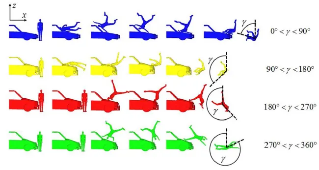
Fig 2.1:different hitting scenarios based on vehicle front design.
As clear from the above figure a typical scenario would involve the pedestrian first making contact to the bonnet leading edge followed by the head making contact with the hood or windshield (depending upon the vehicle front structure). In this exercise, the impact of the head on the hood is examined using LS-Dyna software. In the beginning, a simple sphere representing a child's head was used to set up the case. A rigid wall was used in place of the hood for the sake of simplicity. Next, the child headform model was used instead of a simple sphere and it was oriented at an angle of 50 degrees. The impact was made on a rigid wall and results were recorded. The final simulation was run using the head form model and the car hood model provided for the challenge. All three cases are discussed one by one:
3. Simple head model with rigid wall
3.1 Geometry
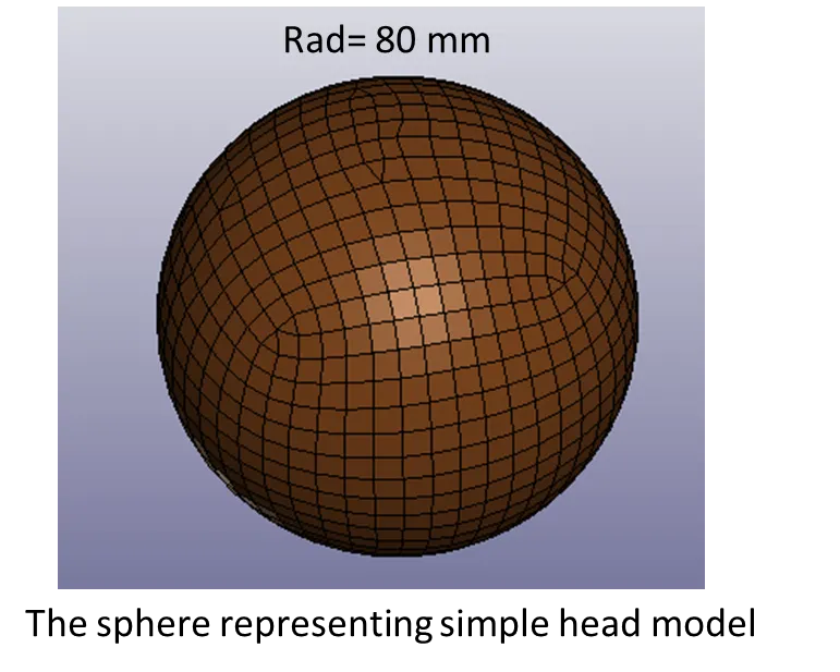
Fig 3.1.1: The sphere is used as a simple head.
A section card and material card were created to provide section and material properties to the model.
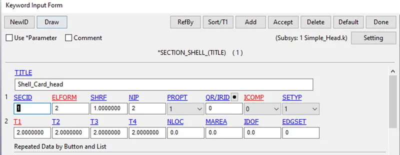
Fig 3.1.2: The Shell section card used for the head model.
As clear from the above figure, a thickness value of 2 mm was assigned and element formulation 2 was used for the shell elements of the head model.
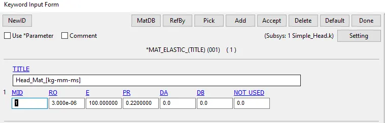
Fig 3.1.3: The elastic material card used for the shell elements of the head model
A rigid wall was created and placed 20 mm apart from the sphere as shown in the attached figure.
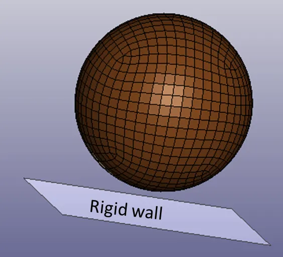
Fig 3.1.4: The Rigidwall created using the create entity tool with the planar option.
3.2 The boundary conditions and other necessary inputs
The Sphere was to be provided with a velocity of 40 kmph which comes out to be 11.11mm/ms in the [kg-mm-ms] unit system used for the exercise. The velocity was imparted using the velocity card available in the initial option in the negative Z direction. An automatic single surface contact card was used for defining contact. In this case, the sphere and rigid wall are going to come into contact upon impact, so a contact definition must be provided for getting proper results. A rigid wall will not undergo any deformation or in other words, it possesses infinite stiffness, so we need to define only the sphere as a slave part of the contact.
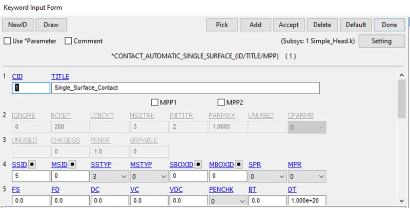
Fig 3.2.2: the automatic single surface contact card used for the model.
A control termination card was used to define a simulation time of 5 ms. In addition to it, an hourglass card was used to capture formation in a better way. The control energy card with an HGEN value of 2 was used to enable the recording of hourglass energy.
Output requests:
The binary D3 plot was used and output was requested at an interval of 0.01 ms. In ASCII options GLSTAT, Nodout, ELout, SLEout etc were used to request output files.
3.3 results and discussion:
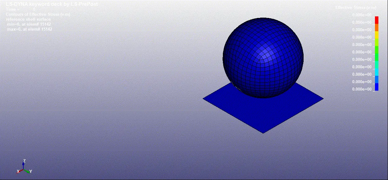
Animation 3.3.1: the impact test simulation of simple head on a rigid wall
HIC value
"Head Injury Criterion (HIC)" is a way to quantify head injury. In the event of a pedestrian's head hitting the bonnet of a car, 95% of the points should not induce serious injuries.
This value is used to find the likelihood of a serious head injury in the event of an impact.
The acceleration data is taken and various quantities can be calculated based on it.
- Severity Index: `SI= int_0^T a(T)^ndt` Where a(t) refers to acceleration, n is an exponent which comes out to be 2.5 for the head.
- Head Injury Criterion (HIC) = `[max t1,t2]*[1/(t2-t1)*int_(t1)^(t2)a(t)dt]^2.5*(t2-t1)`
- A HIC value is then correlated with Abbreviated Injury Scale (AIS) which are as follows:
- Slight damage to the brain with headache, dizziness and no loss of consciousness.
- Concussions with or without skull fracture, less than 15 min of unconsciousness, detached retina, face and nose fracture.
- Concussion with or without skull fracture, more than 15 mins of unconsciousness without severe neurological damage, multiple skull fractures, loss of vision, multiple facial fractures, cervical fracture without damage to the spine.
- Multiple skull fractures with severe neurological damage.
- Concussion with or without skull fracture, more than 12 hours of unconsciousness, haemorrhage in the skull, critical neurological condition.
- Death, cervical fracture with damage to the spine.
These levels are related to the HIC value via probability like at HIC 650 there is :
- 90% probability of AIS level1 injury.
- 55% probability of AIS level 2.
- 20% probability of AIS level 3.
- 5% probability of AIS level 4.
Some important points regarding HIC:
- The condition (t2-t1) <36 ms i.e. the considered time interval must be less than 36 ms, longer deceleration times do not increase the injury risk, according to observations.
- Peak acceleration value must last 3 ms. This requirement has reasons for measurement technique and is supported by the assumption that declarations of shorter durations do not have any effect on the brain.
- A small HIC value does not mean the head injury will be of low levels.
- Likewise, a high HIC value does not mean high-level injuries.
- The real meaning is that with a higher HIC value the probability of getting a high-level head injury is high.
In LS-Dyna the HIC value can be easily calculated from the inbuilt HIC function.
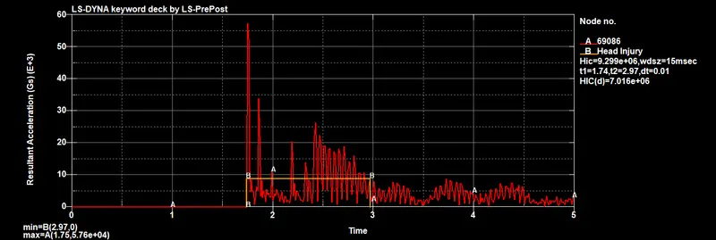
Fig 3.3.2: The HIC15 value calculated from the resultant acceleration of a node on the sphere
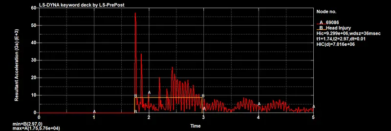
Fig 3.3.3: The HIC36 value calculated from the resultant acceleration of a node on the sphere
Manual calculation of HIC value:
- For manual calculation, we need to find approximate constant acceleration in the considered time interval.
- It comes out to be `a(t)= 9e3g` for the period between t=1.7 ms and t=3 ms.
- Then `int_(t=1.7ms)^(3ms)(9e3*g)dt` = 9e3*1.3 [ms*g]
- This gives avg. acceleration as `[int_(1.7ms)^(3ms)(9e3g) dt]/(3ms-1.7ms)= 9000g`
- Finally, HIC=`(t_2-t_1)*(avg. acc.)^2.5` `[s*g^2.5]`
- So HIC = `0.0013[s]*(9000*g)^2.5= 9.89635e6 [s*g^2.5]`
- The calculated value is approximately equal to the value obtained by HIC function in the LS-Prepost (9.299e6).
Energy plots
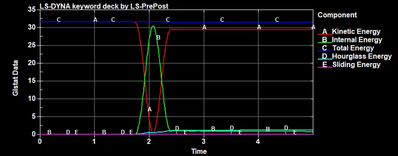
Fig 3.3.4: The energy plots for the simulation
The total energy remains constant, sliding and hourglass energies are very low, this indicates the simulation was ok and served the purpose.
4. The Pedestrian Head form and rigid wall
This time a pedestrian headform was used for the simulation. A hood was substituted with a rigid wall for the sake of simplicity. A headform is a model mimicking the behaviour of a human head. There are guidelines and standards for the headform. Some of them as mentioned on the Automotive Industry Standard's website are:
- The child headform impactor shall be made of aluminium, be of homogenous construction and be of spherical shape.
- The overall diameter shall be 165 ± 1 mm.
- The mass shall be 3.5 ± 0.07 kg.
- The moment of inertia about an axis through the centre of gravity and perpendicular to the direction of impact shall be within the range of 0.008 to 0.012 kgm2. The centre of gravity of the headform impactor including instrumentation shall be located in the geometric centre of the sphere with a tolerance of ± 2 mm.
- The sphere shall be covered with a 14 ± 0.5 mm thick synthetic skin, which shall cover at least half of the sphere.
- Similar guidelines are there for the instrumentation used for taking measures by placing an accelerometer to the head form.
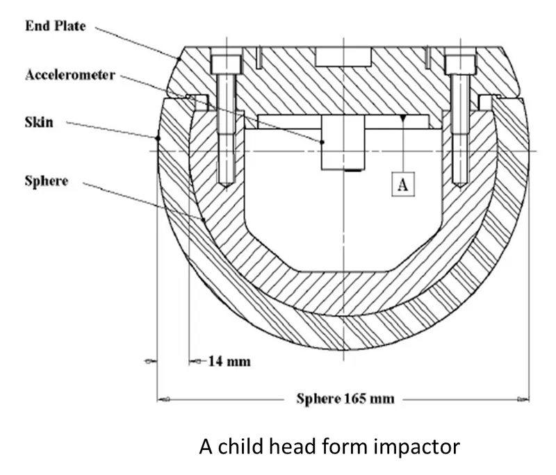
Fig 4.1: The schematic of a child headform impactor.
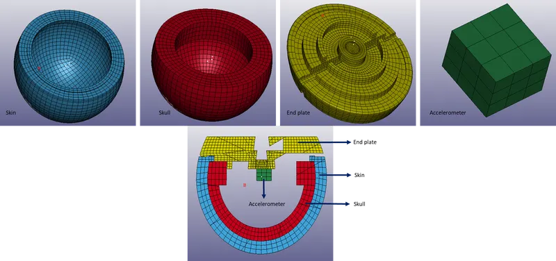
Fig 4.2: The FE model of the child headform
The standard models such as headform are often provided by a reputed organisation like Humanatics or LSTC. The user is supposed to maintain the purity of the model and not make any changes to the data. This requires the use of *include keywords to call another file inside the main file. It is called organising a multi-include file which is a very handy method when it comes to modelling large assemblies. Especially in the cases where each subsystem is prepared by different groups.
The head form model was called into the main file using the *include transform keyword. It was done to orient the head form at an angle of 50 degrees with the Y-axis.
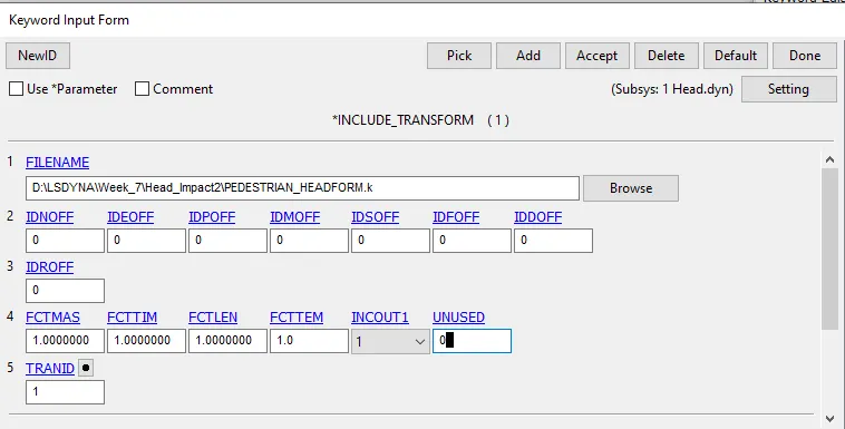
Fig 4.3: the include transform card used to call the head form file
In this card the OFF boxes refer to the ID offset value for nodes, elements and other entities in the imported model. The TranId refers to a transformation card defined using the *define_transformation card as shown below.
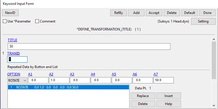
Fig 4.4: the Define_transformation card used for orienting the head form model
A1 to A3 values refer to the direction cosines for the axis of rotation, A4 to A6 values refer to the coordinates of a point through which the axis of rotation needs to pass. A7 refers to the angle value in degree for the rotation.
Then a rigid wall was created in a manner similar to the one used for the simple head simulation and an initial velocity card was used to assign a resultant velocity of 11.11[mm/ms] in the negative direction along the axis of rotation. This was done by decomposing the velocity in x = -11.11 cos(50) and velocity in Z direction = -11.11 sin(50).
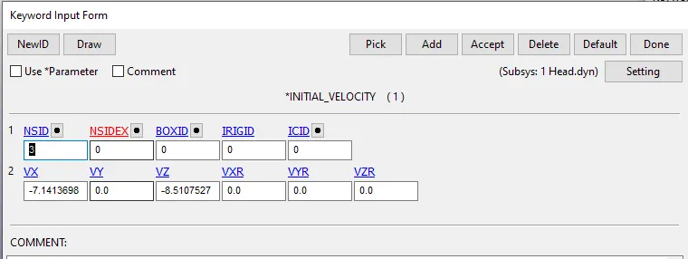
Fig 4.5: The initial velocity card used for imparting velocity to the head form
An automatic single surface contact card was used to define the contact between the rigid wall and the skin of the head form. Output requests were the same as used in the previous simulation. This time a history node card is used in the headform model for measuring the history of the accelerometer node which is in the accelerometer block.
The results and discussion
Animation: The headform crashing on the rigid wall.
After that, the HIC values were calculated using the HIc function of the LS Pre-Post.
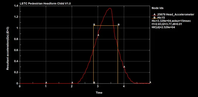
Fig 4.6: The HIC 15 value calculated from the plot of the resultant acceleration.
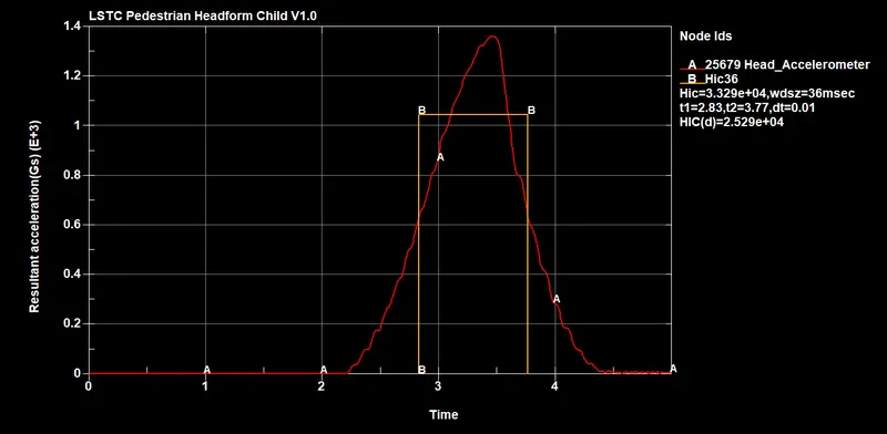
Fig 4.7: The HIC 36 value calculated from the plot of the resultant acceleration.
The impact is captured well in the acceleration plot, peak at 3.5 ms denotes reversal of the direction after impact. The higher value of HIC may be attributed to the fact that the rigid wall does not deform and all of the impact energy is absorbed by the head form itself.
Then Von-Mises stress was plotted for an element ID 3302, the graph is shown below.
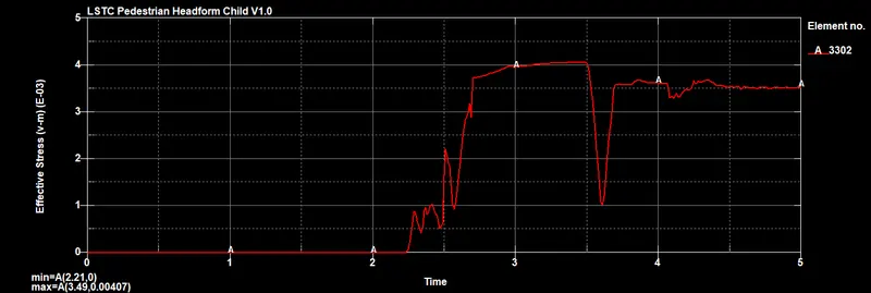
Fig 4.8: The effective stress developed in element near the bottom
The rise and fall can be attributed to the deformation and elastic recovery of the skin after coming into contact with the skull elements which are much stiffer.
5. The Head form and the hood model
This time a meshed hood model was used instead of a rigid wall for the simulation. The orientation of the head form was kept exactly similar and all other inputs were same except the addition of the material and section properties for the hood model.
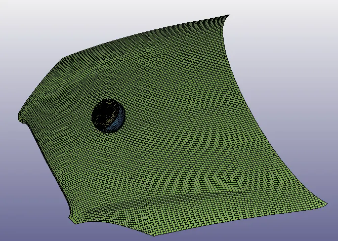
Fig 5.1: the headform and the hood model
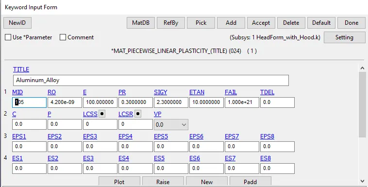
Fig 5.2: The material card used for the hood model.
A shell section card with ELF 2 and a thickness of 1.5 mm was used for the hood elements. The velocity was kept identical to the previous case and an extra contact card was provided making the hood the master and the skin as the slave.
Animation: Head form impact with hood
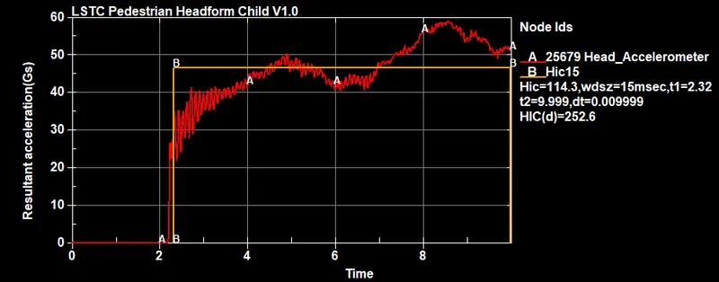
Fig 5.3: the HIC 15 value calculated for the model
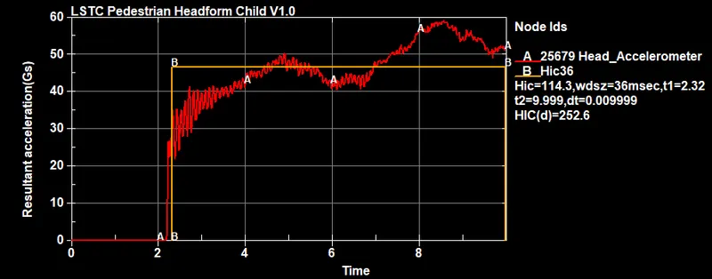
Fig 5.4: The HIC 36 value calculated for the model
The Hic value is very low, it indicates the chances of serious injury like AIS level 5 are minimum for the setup used in this exercise. The lower HIC value in comparison to the rigid wall simulation can be attributed to the fact that the hood crumples and absorbs the energy of impact, unlike the rigid wall.
Stress comparison for the element 3302 with the rigid wall simulation.
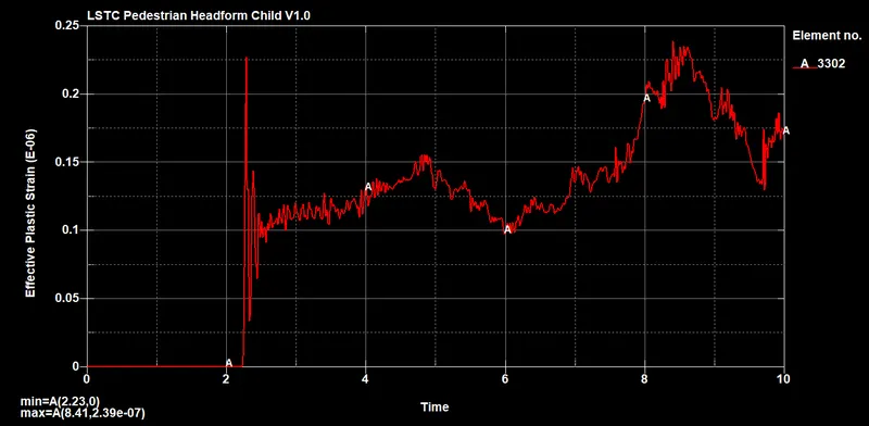
Fig 5.5: the stress plot for the 3302 element on the skin of the head form
A much lower value of the stress is developed and this can be attributed to the shock being absorbed by the hood during impact.
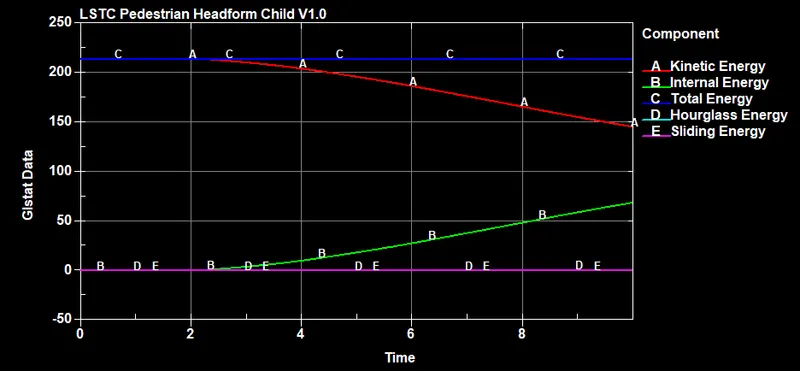
Fig 5.6: the energy plot for the contact interface
The total energy remains constant, sliding and hourglass energies are very low, this indicates the simulation was ok and served the purpose.
Conclusion
- This exercise was aimed at making the user familiar with the pedestrian head simulation. The more accurate results would require a detailed modelling of the material for the hood and a much higher run time.
- Different steps involved in the HIC calculation were learned and an overview of how to relate the HIC value to the severity of the injury was developed.