Week-6 : Turbocharger Modelling
Aim : Turbocharger Modelling
objectivie :
- List down different TC and locate examples from GT Power
- Explore tutorial number 6 and 7
- Plot operating points on compressor and turbine maps
- In which application Variable Geometry Turbine is beneficial?
- Explore example- Diesel VGT EGR and understand the modeling part
theory :
need for different type of turbo charger
Different types of turbochargers are used based on the specific requirements of the engine and the vehicle. Here are some of the reasons why different types of turbochargers are needed:
-
Engine Size: Turbochargers are available in different sizes to match the displacement of the engine. Larger engines require larger turbochargers.
-
Boost Pressure: Different types of turbochargers can provide varying levels of boost pressure to suit the needs of the engine.
-
Engine Speed: Turbochargers that are optimized for high engine speeds are needed for high-performance engines.
-
Engine Load: Different types of turbochargers can respond to changes in engine load in different ways. For example, a variable geometry turbocharger (VGT) can be adjusted to provide more or less boost as needed.
-
Efficiency: Different types of turbochargers can have different levels of thermal and hydraulic efficiency, affecting their performance and longevity.
-
Cost: The cost of the turbocharger is an important consideration, and different types of turbochargers can have different price points.
different types of turbo charger
Turbochargers are classified based on the design of the turbocharger, the type of exhaust gas energy they use, and the method used to control the boost pressure. Some of the common types of turbochargers include:
-
Wastegate turbochargers: They use a mechanical wastegate to control boost pressure.
-
Variable geometry turbochargers (VGTs): They use a hydraulic or electric actuator to adjust the nozzle vanes, which control exhaust gas flow.
-
Twin-scroll turbochargers: They use two separate inlets and scrolls to direct the exhaust gas to the turbine wheel.
-
Electric turbochargers: They use an electric motor to spin the turbine wheel, eliminating lag time.
-
Dual-stage turbochargers: They use two turbochargers in series, providing high boost pressure and low-end torque.
-
Sequential turbochargers: They use two turbochargers, one small and one large, that work together to produce boost pressure.
-
Biturbochargers: They use two turbochargers, one for each bank of cylinders in a V-type engine.
most common turbo chargers are
- Wastegate Turbocharger: wastegate A turbocharger is a turbocharger system that uses a pressure valve to control the amount of boost created by the turbocharger. The valve helps regulate the pressure created by the turbocharger so that it does not exceed the desired level, allowing the engine to run at peak efficiency.
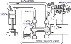
Wastegate Turbocharger
Example: Garrett T25 Turbocharger, Holset HX35 Turbocharger.
- Variable Geometry Turbocharger (VGT): A VGT turbocharger has adjustable vanes that control the flow of exhaust gases to the turbine. The vanes can be adjusted to optimize the boost pressure for a given engine speed and load.
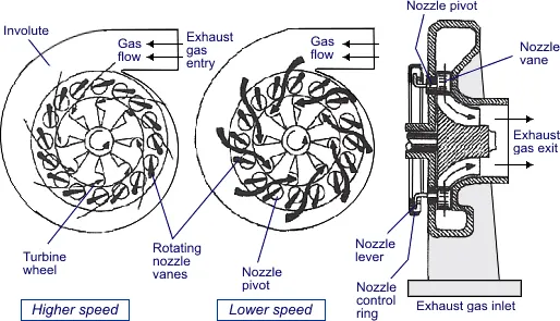
Variable Geometry Turbocharger (VGT)
Example: BorgWarner AirWerks S300SX3 Turbocharger, Mitsubishi TD05HR-16G6-10.5T Turbocharger.
Tutorial In this tutorial the single cylinder DICI engine created in Tutorial “Basic Cylinder Engine” will be converted
to a six cylinder diesel engine with turbocharger. A manifold will be built for the intake and exhaust.
Explore tutorial number 6 and 7
Before starting this process, it is important to have the following data:
• Measured engine volumetric efficiency or air mass flow data
• Turbine performance map data
• Compressor performance map data
• Measured turbocharger shaft speed data
tutorial 6 and tutorial 7 tubro step 1
both of these tutorials are same Run the Base Engine without the Turbocharger. the basic engine has been completed from the compressor outlet to the turbine inlet.
The compressor outlet and the turbine inlet conditions have already been set through EndEnvironment boundaries. In this way, the base engine performance can be tested for errors. This would indicate if the base engine model (manifolds, valves, cylinders, etc.) is properly modeled before we start complicating the system with the turbocharger.
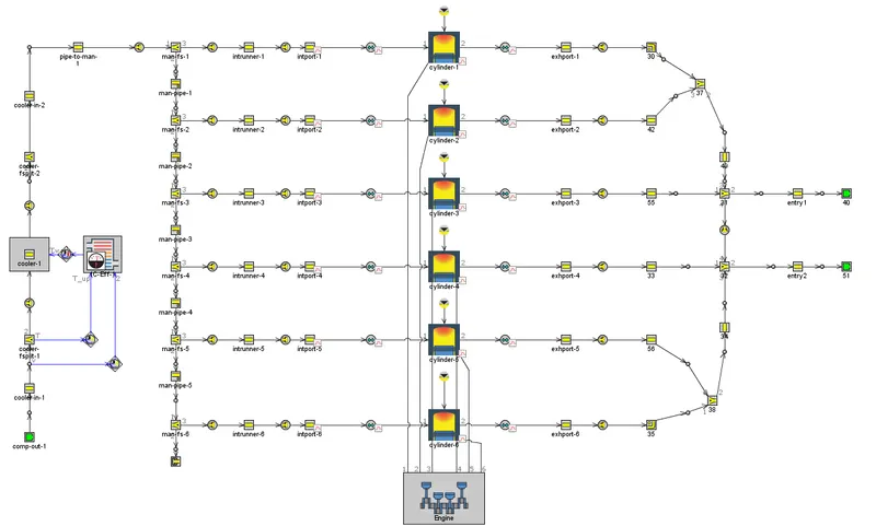
step 1 without compressor and turbin(outlet of compressor and inlet of turbine end environment)
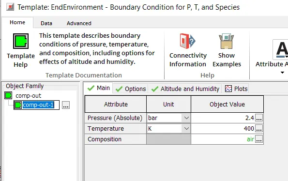
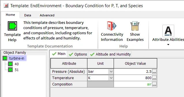
compressor outlet and turbine inlet setup
from compressor outlet air passsed through intercooler and to engine manifold after combution in engine cylinder exhuast gas is sent to turbine inlet end environment
results
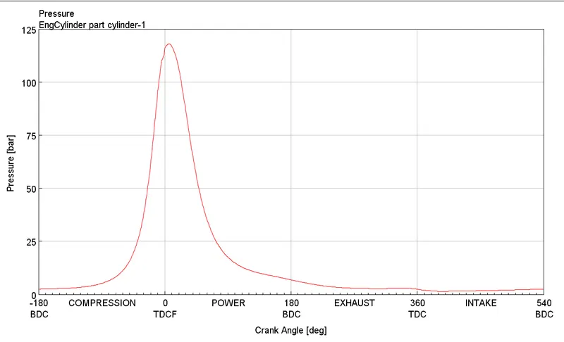
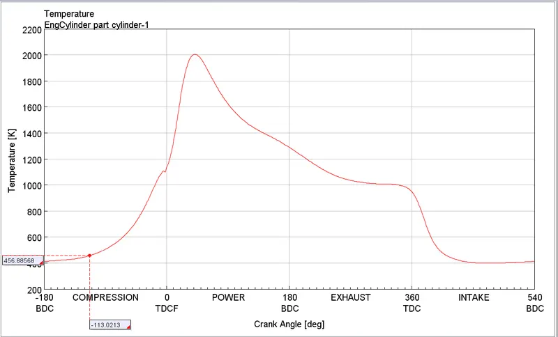
pressure and temprature in cylinder
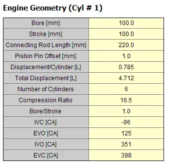
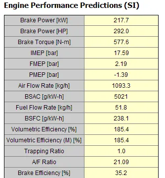
engine performence
7.2 Model Engine with No Turbine (only Compressor)
The second step is to add the compressor to the engine, while keeping the turbine inlet boundary modeled with EndEnvironment parts. This will allow us to independently study the compressor performance before complicating the engine system with the turbine.
modeled before we start complicating the system with the turbocharger.
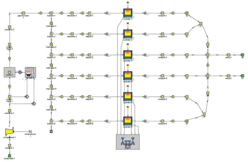
step 2 engine with compressor and turbine inlet end environment
in compressor setup compressor mapdata is importent there are two ways to input compressor map data
1. input all data like RMP , mass flow rate , pressure ration and efficiency
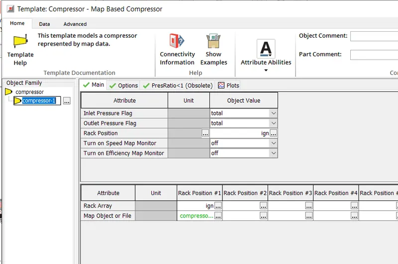
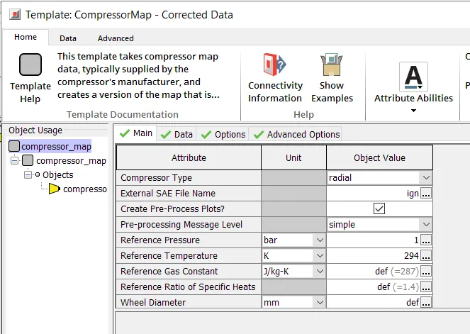
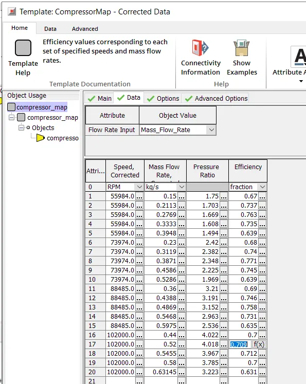
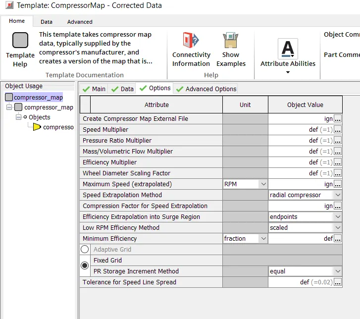
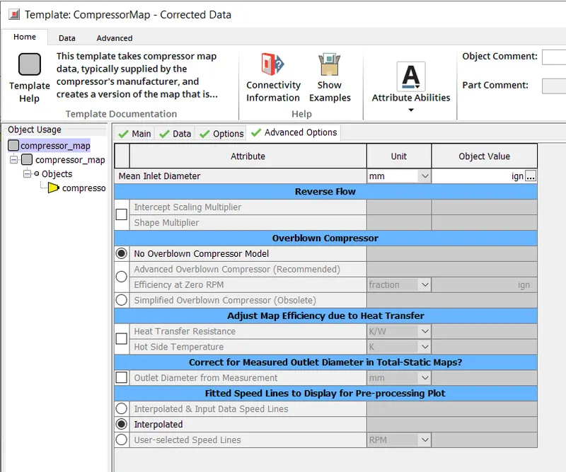
2. upload all of above date in
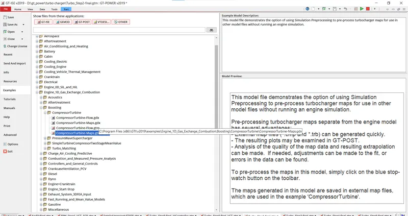
is example problem and preprocess the simulation and the simulation end up downloading a CMP file upload that file in
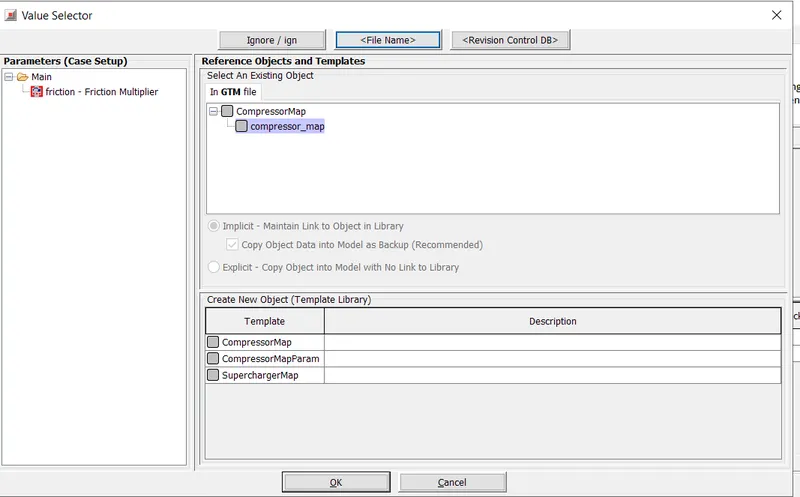
inplace of file name
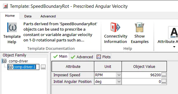
compressor runner
remaining all setup same as previous
result
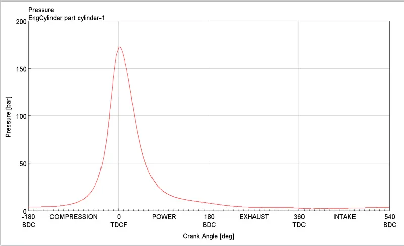
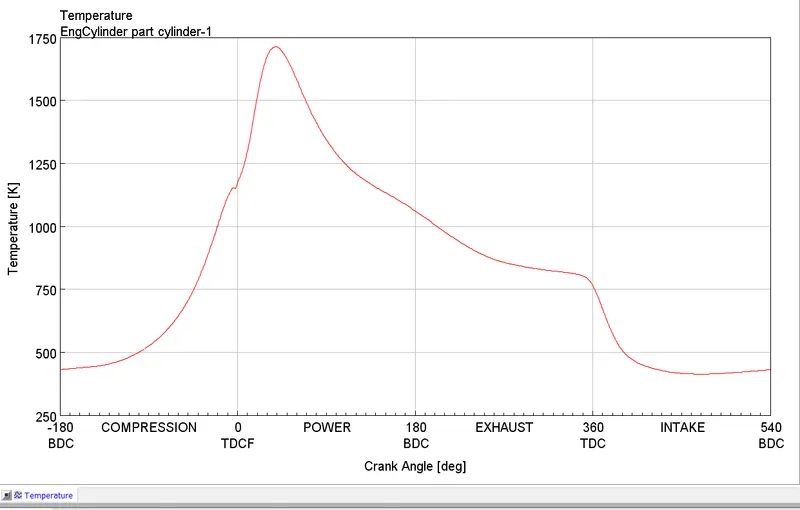
pressure and temprature in cylinder
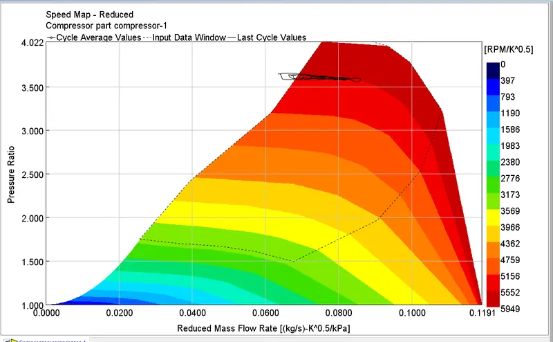
compressor performence
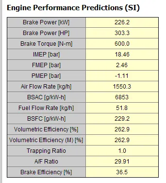
engine performance
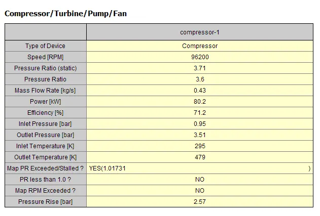
compressor performance
there is increase in airflow ratio compared to last step because the outlet presssure of compressor is more then the last simulation inlet environment pressure
7.3 Model Engine with No Compressor (only Turbine)
The third step is to add the turbine to the engine, while keeping the compressor outlet boundary modeled with EndEnvironment parts. This will allow us to independently study the compressor performance before complicating the engine system with the turbine.
add the turbine and replace the compressor with an EndEnvironment.
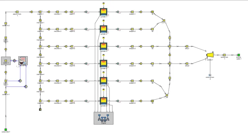
step 3 tunbine is added to engine with compressor outlet as end environment to inlet
adding turbine is simmilar to the compressor
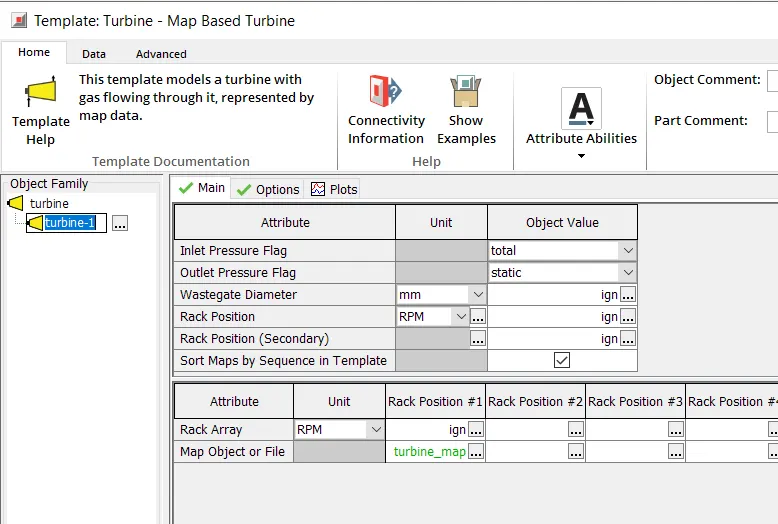
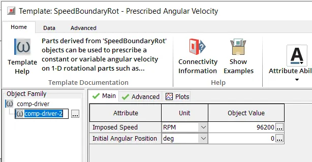
tubine and turbine runner
Result
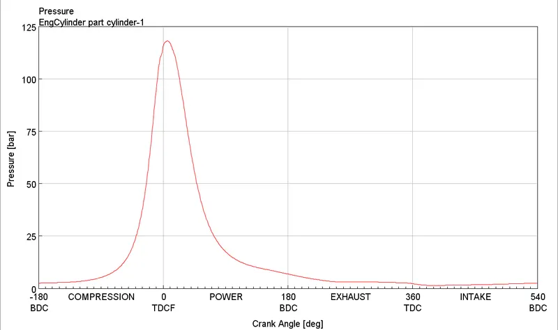
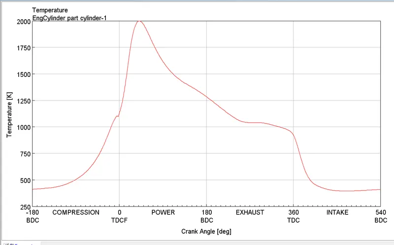
pressure and temprature in cylinder
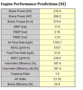
engine performance
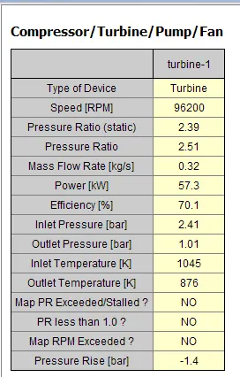
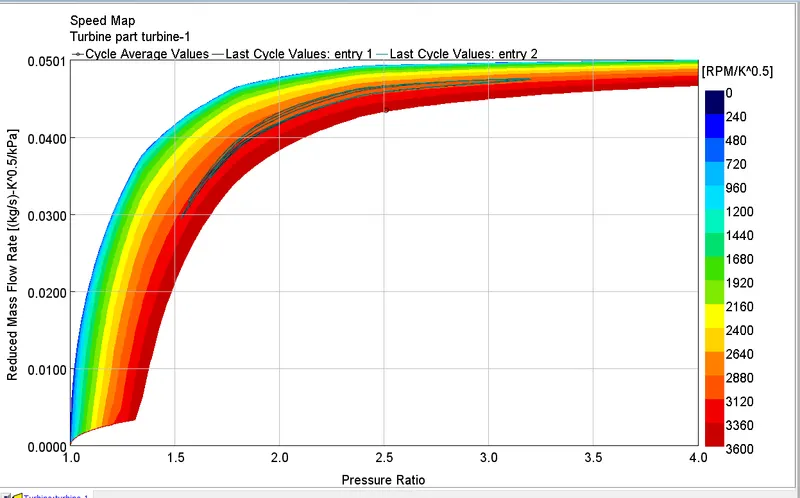
turbine performance
the inlet pressure and tempreture is similar to case 1 and engine performance is droped due to the rotaion of turbne is done by engine and the turbine work is not utilised
7.4 Calibrate the Compressor and Turbine Power
The fourth step is to add the compressor and turbine to the engine. This will allow us to independently study the compressor performance before complicating the engine system with the turbine.
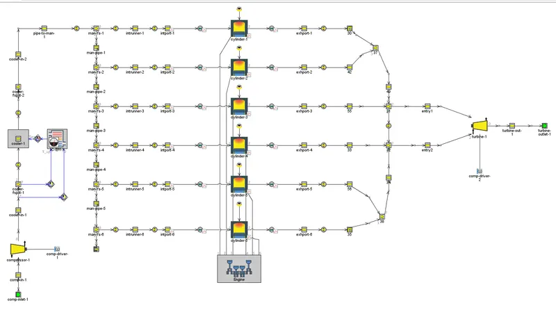
step 4 with turbine and compressor engine are connected throgth runner
the compressor and turbine setup same as step 2 and step 3 without shaft
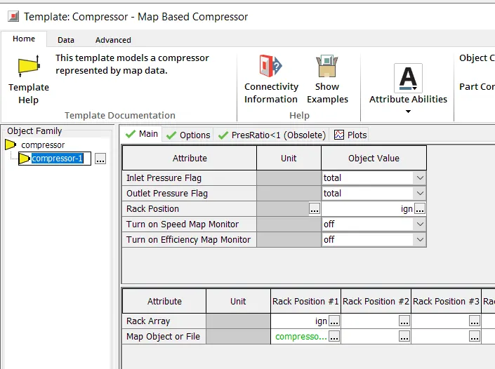
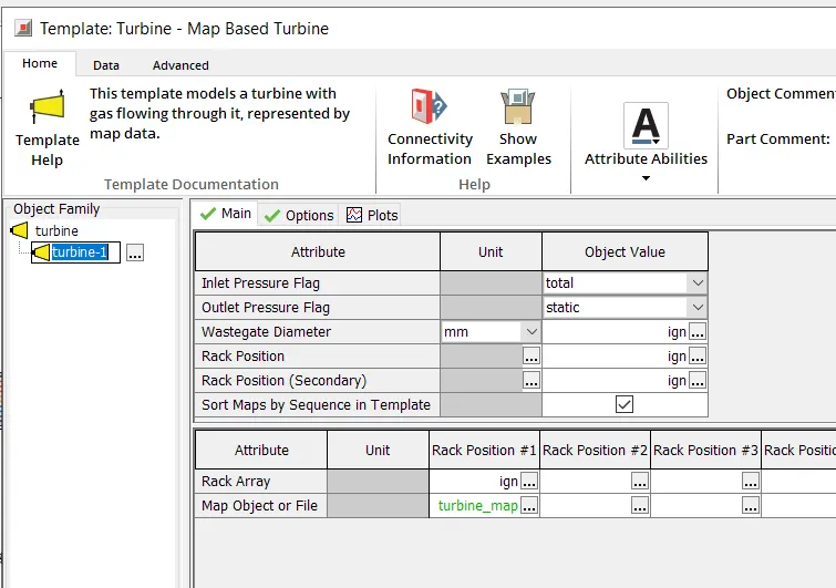
compressor and turbine
Result
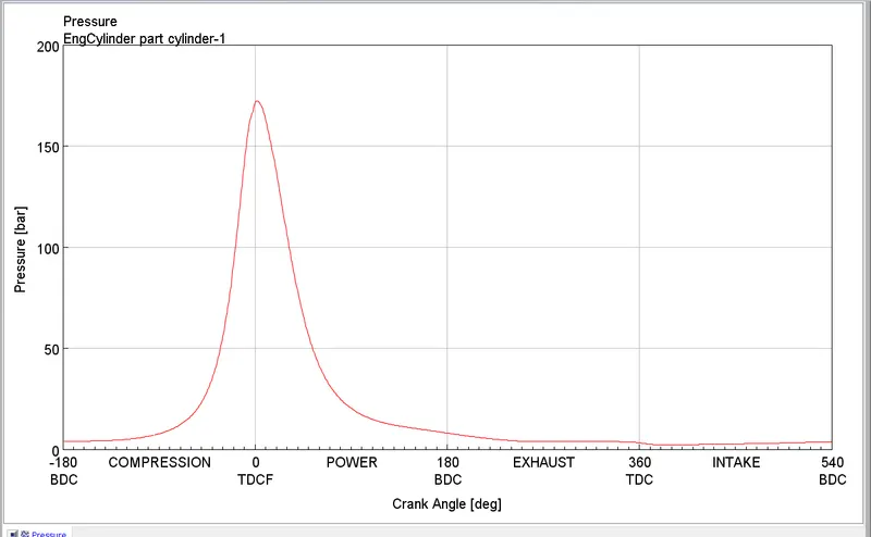 '
'
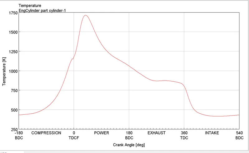
presssure and temprature
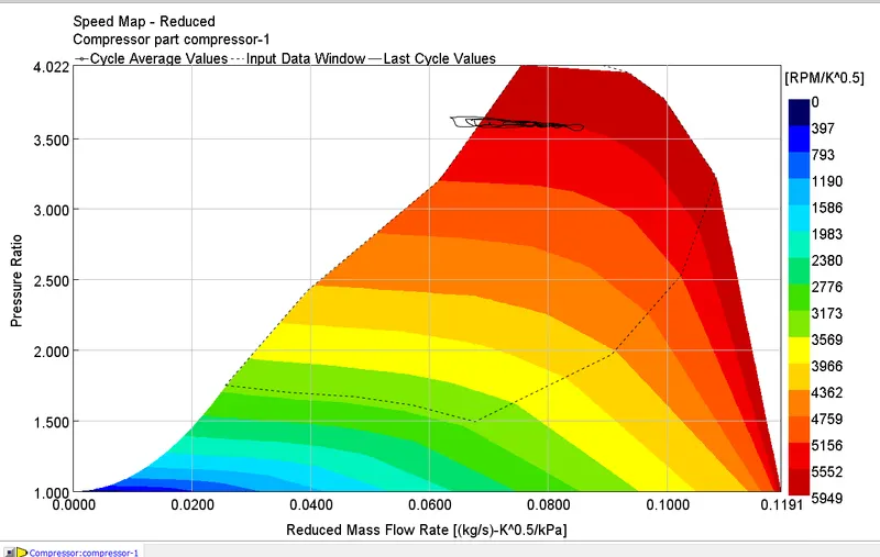
compressor
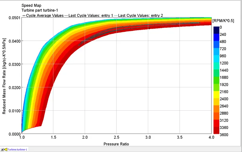
turbine performance
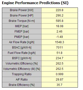
engine performance
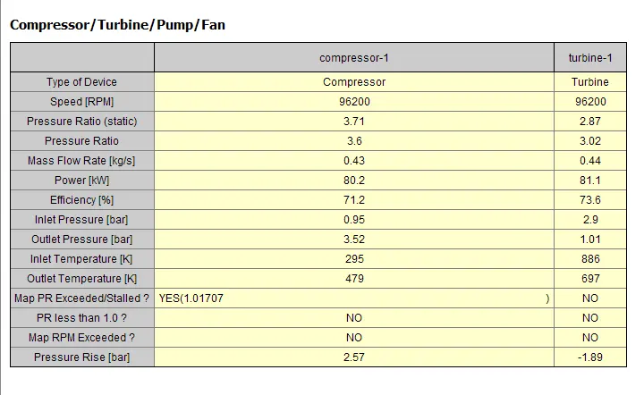
compressore and turbine perfrmance
there is improvement in BSFC of engine compare to step 2 result and remaining all other remain same
7.5 Complete the Turbocharger
complete the turbocharger by connecting the turbine and compressor with a 'ShaftTurbo' object.
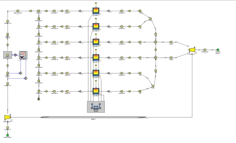
step 5 engine with fully turbocharged
the setp is same as previous case but instead of runner shaft is commnected b/w compressor and turbine wtih exhuast gas turbine runs and with shaft compressor runs
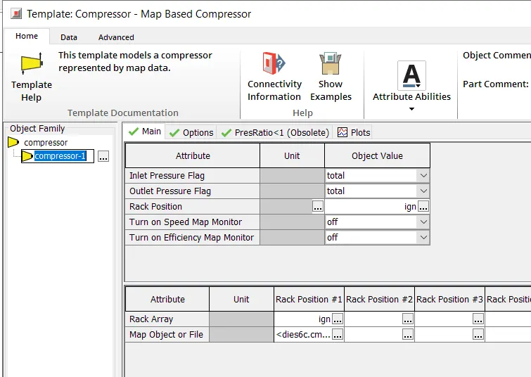
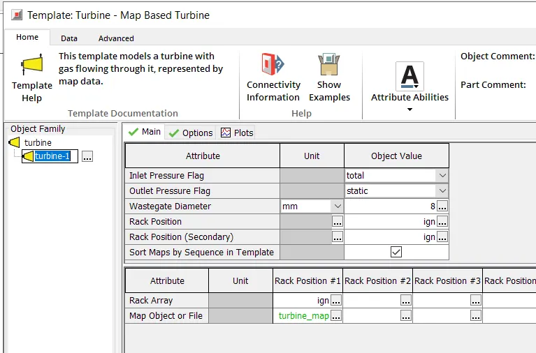
compressor and turbine setup
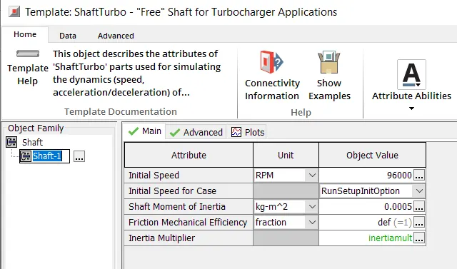
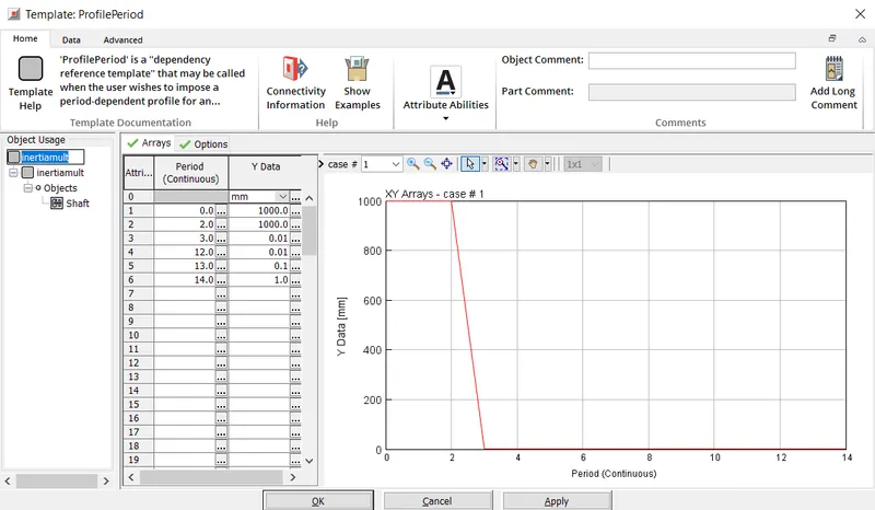
shaft setup
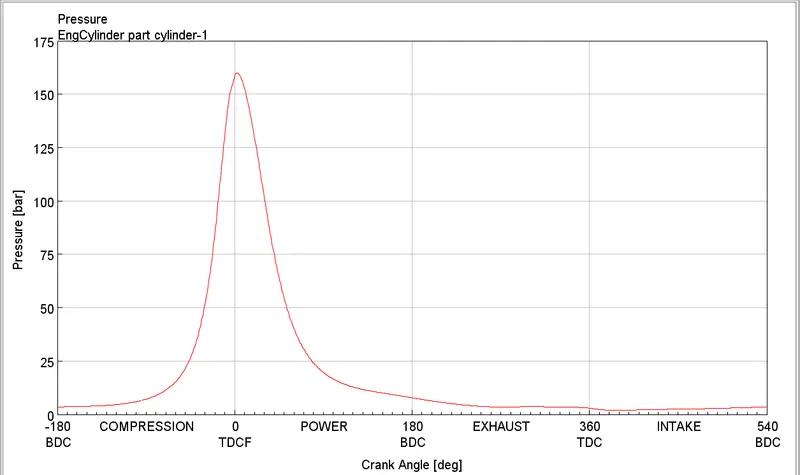
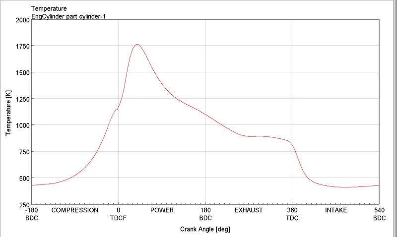
Result
 \
\
pressure and temprature
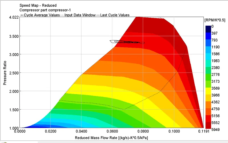
compressor preformance
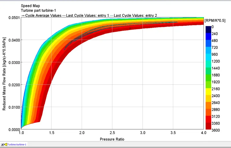
turbine performance
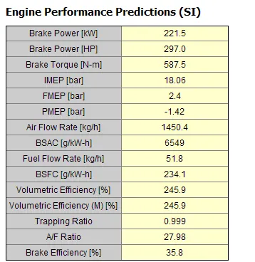
engine performance
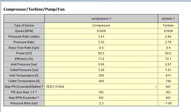
engine performance
results are similar to step 4 solution
Plot operating points on compressor and turbine maps
ploting operating poins of turbine and compressore are provided turbochager manifacture in CMP file or they provied the ratation speed mass flow rate , pressuure ratio and effiency
using this CMP and TRB file generated in GT power
to genarate CMP and TRB file there is an example problem is ther using that files are genarated
example problem
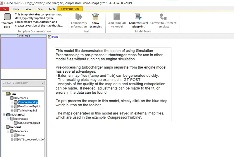
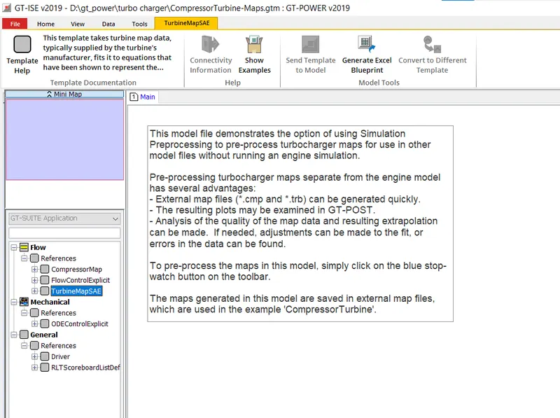
open the object and enter the input dat and preprocess the simulation the rsults will give CMP and TRB files
In which application Variable Geometry Turbine is beneficial?
The Variable Geometry Turbine (VGT) is commonly used in automotive and industrial applications, particularly in diesel engines. VGT can improve the engine's performance by increasing the boost pressure at low engine speeds and reducing the boost pressure at high engine speeds. This can result in improved fuel efficiency, reduced emissions, and better overall engine performance. VGT can also be used in other applications such as power generation and marine propulsion systems where a turbocharger is required.
advantages of VGT
Variable Geometry Turbochargers (VGTs) have several advantages over traditional fixed geometry turbochargers:
-
Improved Boost Control: VGTs can alter their geometry to maintain optimal boost pressure throughout the engine's RPM range, improving engine response and performance.
-
Increased Engine Efficiency: VGTs can provide improved exhaust gas scavenging, reducing engine pumping losses and increasing engine efficiency.
-
Improved Emissions: VGTs can help reduce emissions by enabling more precise control of air-fuel ratios, leading to cleaner combustion and reducing the amount of particulate matter in the exhaust.
-
Better Driving Experience: VGTs can provide faster throttle response, improved low-end torque, and improved driveability, leading to a more enjoyable driving experience.
-
Cost-effective: VGTs can be cost-effective as compared to other turbocharging technologies, especially in high-volume applications.
Explore example- Diesel VGT EGR and understand the modeling part
there anre diffrent types of VGT EGR example present in GT Power
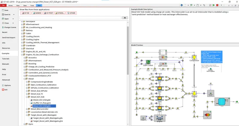
VGT EGR example
in this exapmle the 4 cylinder engine whih is turbo charged where fraction of xhuast gas goes to EGR and remaining gass to turbine which is controlled by VGR controller
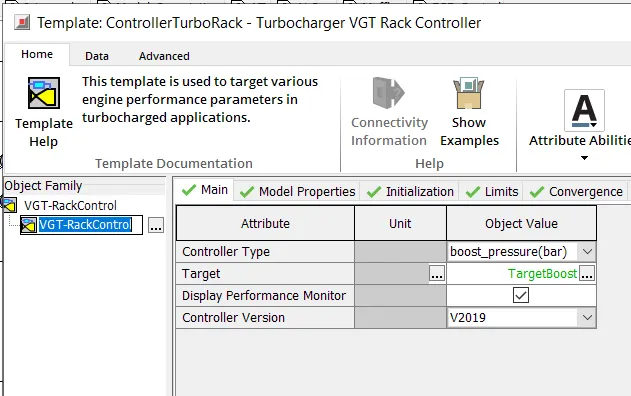
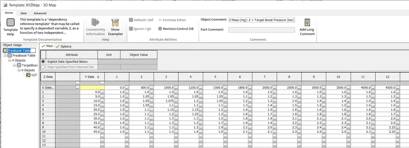
the setup is simmilar to all other compressor and turbine set up but the turbine profile is defined for for each rack position and the rack controll is controlled by VGR rack controller whic controlles the angle of vanes allowing the amount of exhuast gas in turbine to controll the over speeding of turbie and conrolle the boost pressure
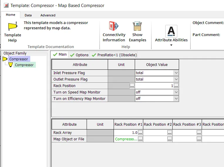
compressor
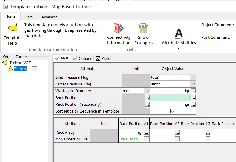
turbine
Results
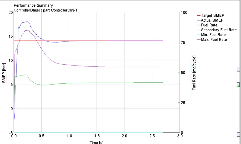
performance summary of diesel injector
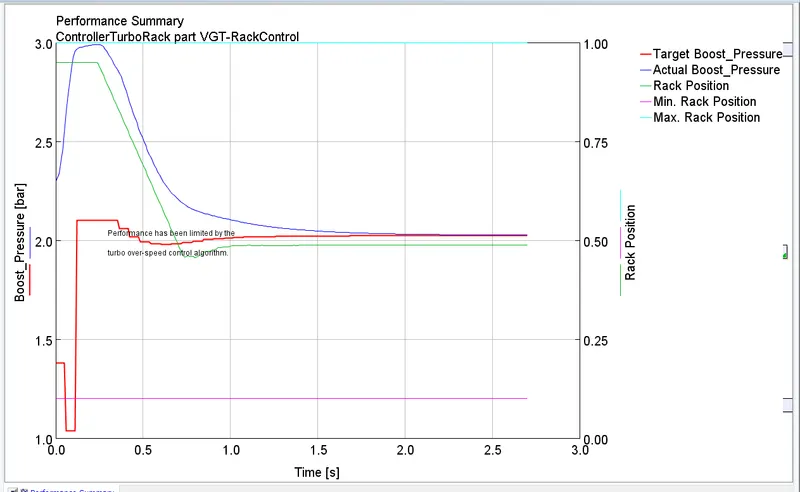
perforance rack controller performance
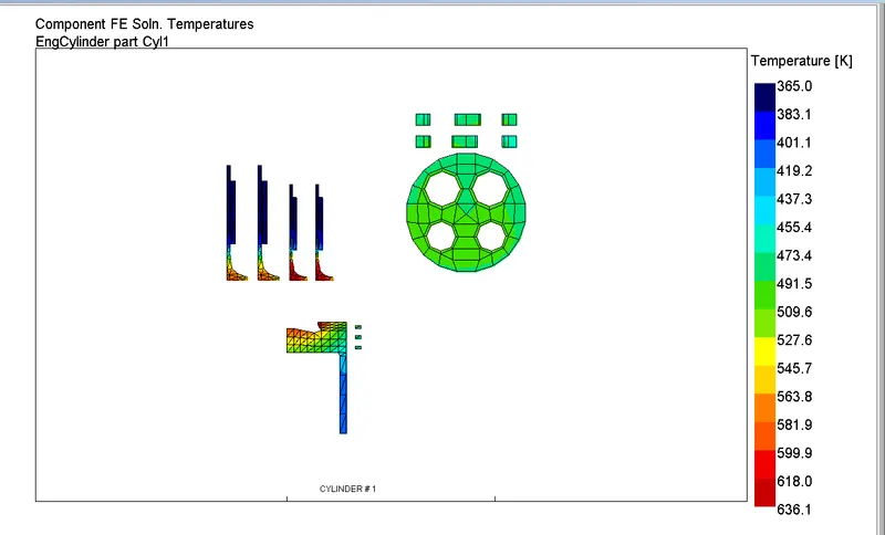
temprature
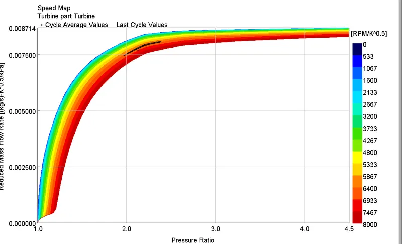
turbine performance
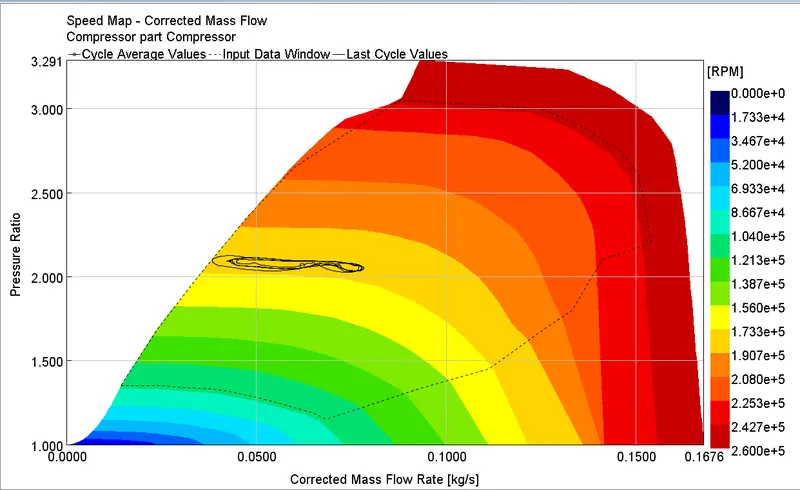
compressor
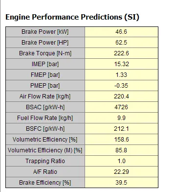
engine performance
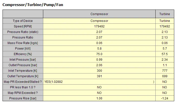
compressor
conclusion
in normal turbocharge engine there some time over speeding of turbine is one of the major concern
but with wesgated tuerbo charge its controlled but is constant if whenever to control amout of exhuast gas in turbine done mechanically or now days ontroled by actuator
in VGT turbine the vane angles are controlled with speed and boost requirement
some of explored example are here