Week 9 - Parametric study on Gate valve.
Challenge 9
Aim: perform a parametric study on the gate valve simulation by setting the opening from 10 % to 80%.
Objective: perform a parametric study on the gate valve simulation by setting the opening from 10 % to 80%.
- Obtain the mass flow rates at the outlet for each design point.
- Calculate the flow coefficient and flow factor for each opening and plot the graph.
- Discuss the results of the mass flow rate and flow coefficient.
Introduction:
Gate valve: Gate valves are designed for fully open or fully closed service. They are installed in pipelines as isolating valves and should be used as control or regulating valves. Operation of a gate valve is performed doing an either clockwise to close (CTC) or clockwise to open (CTO) rotating motion of the stem. When operating the valve stem, the gate moves up- or downwards on the threaded part of the stem.
Application of Gate valve
Gate valves are often used when minimum pressure loss and a free bore is needed. When fully open, a typical gate valve has no obstruction in the flow path resulting in a very low-pressure loss, and this design makes it possible to use a pipe-cleaning pig. A gate valve is a multiturn valve meaning that the operation of the valve is done by means of a threaded stem. As the valve has to turn multiple times to go from open to closed position, the slow operation also prevents water hammer effects.
Gate valves can be used for a vast number of fluids. AVK's gate valves are suitable under the following working conditions:
- Potable water, wastewater and neutral liquids: temperature between -20 and +70 °C, maximum 5 m/s flow velocity and up to 16 bar differential pressure.
- Gas: temperature between -20 and +60 °C, maximum 20 m/s flow velocity and up to 16 bar differential pressure.
Solving & Modelling approach
Geometry: gate valve is imported to space claim application then fluid volume extracted using volume extracted command then gate is moved up by 10 mm using move command and update the fluid volume body in context.
The above step is for moving gate to create a parameter go to group menu create parameter button will be there which enable after moving gate then select the moved element the parameter is created now pull the bottom for 800 mm for both side and update the volume in context.
And close the application
Mesh: name the inlet and outlet by face selection and mesh the component for required element size and close the application
Setup: gravity is given for z direction i.e 9.81 m/s^2
Solver setup
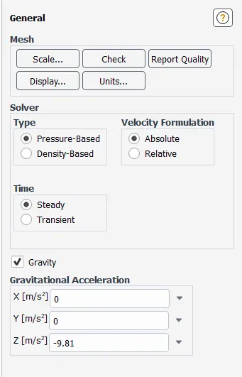
Fig 1 solver setup
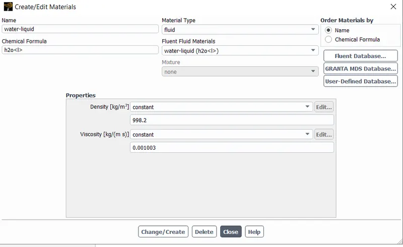
fig 2 material set up
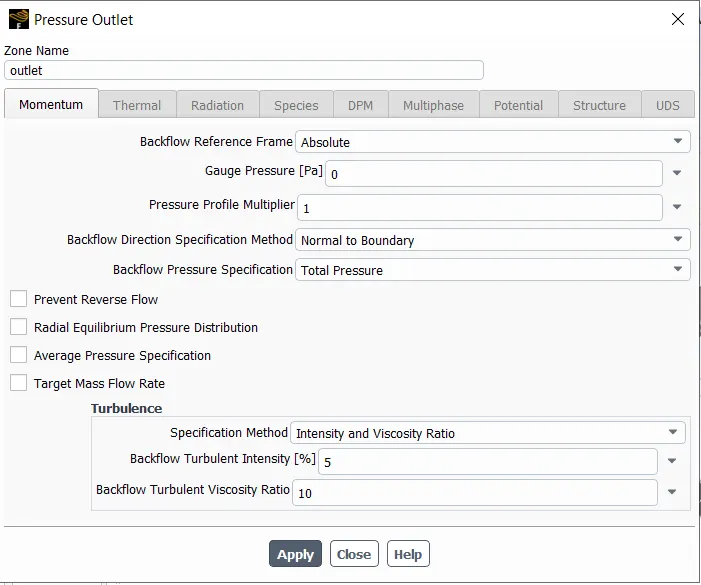
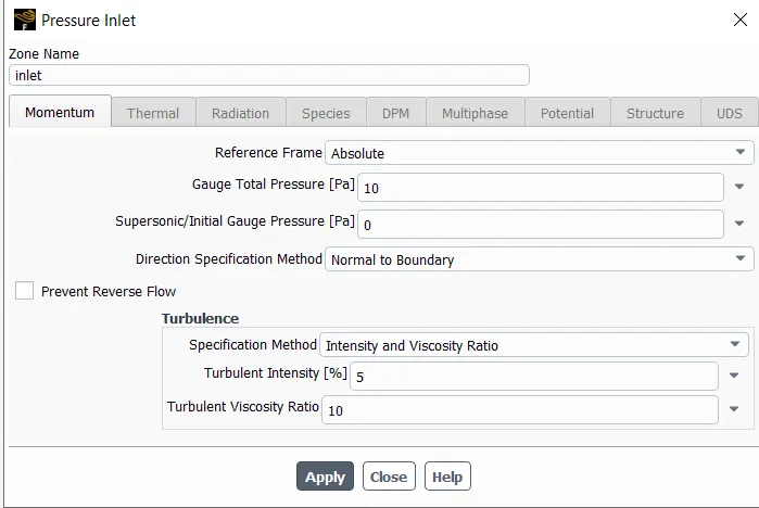
fig 3 boundary condition for inlet and outlet
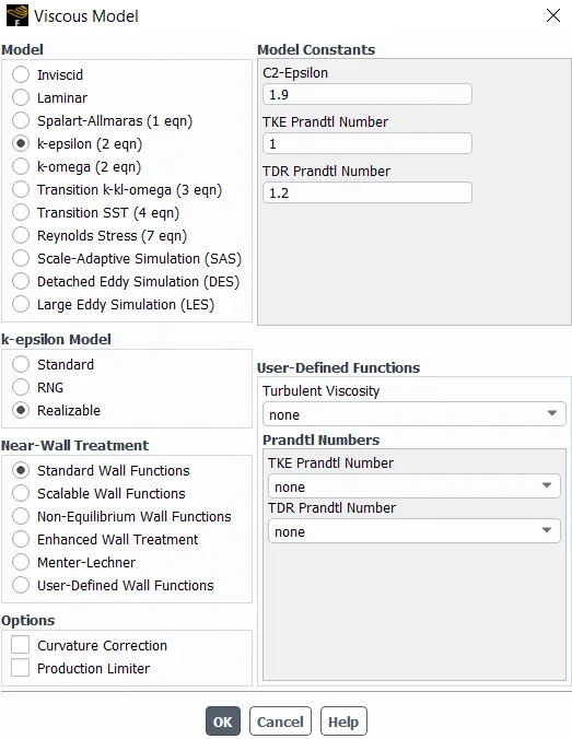
fig 4 viscous model
report defination for mass flow rate and volume flow rate the output parameter is created
intialize solution satndard with optrion
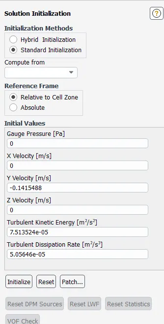
fig 5 solution intialization parameters
insert a plane to create contour and animation
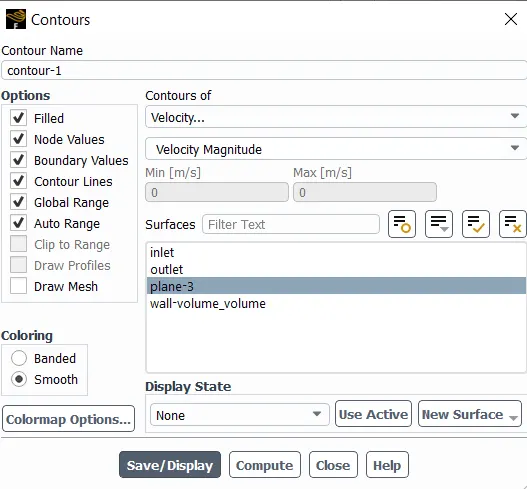
fig 6 contour set up
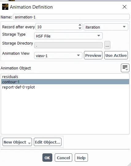
fig 7 animation set up
calculate the solution for 300 iteration
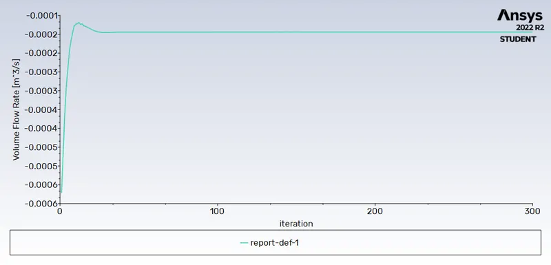
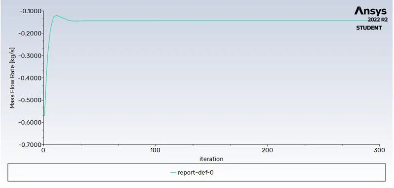
fig 8 volume flove rate and mass flow rate at outlet
once the calculation is done close the application at the botom of project parameter can be seen open that there will be table of design point pop wil be there in that enter the gate opening distance in mm enter the value from 20 to 80 mm and update all design points wait till alcalculation done
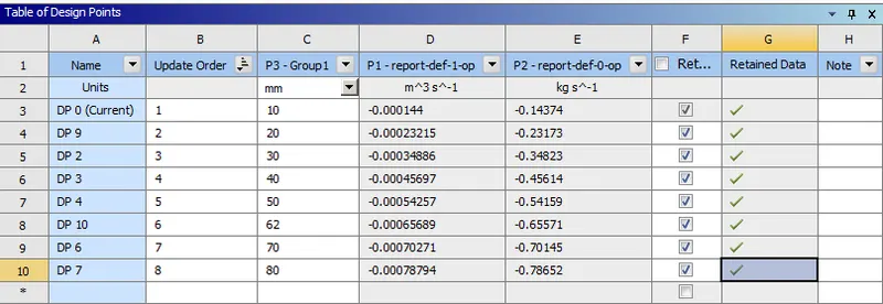
fig 9 degign points with output parameters
Results
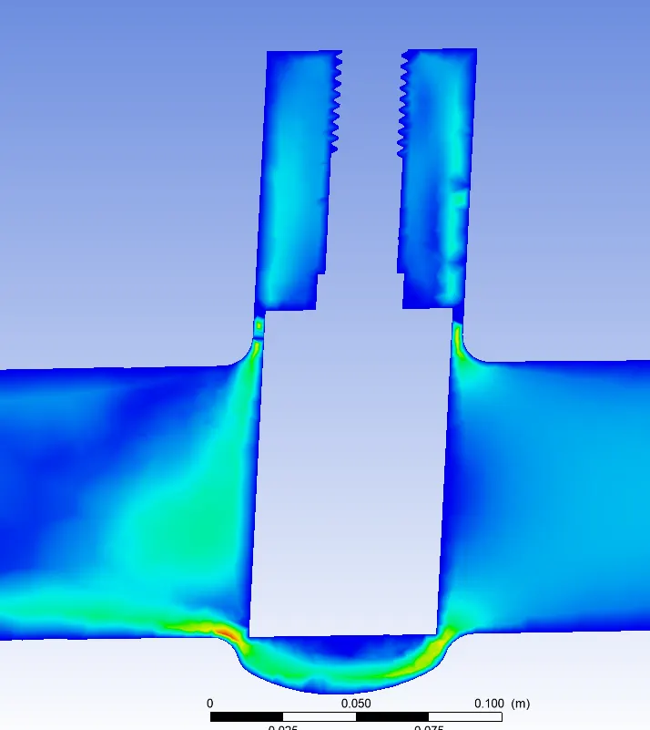
fig 10 valve open for 10 mm
mass flow rate -0.14374 and volume floe rate =0.000144
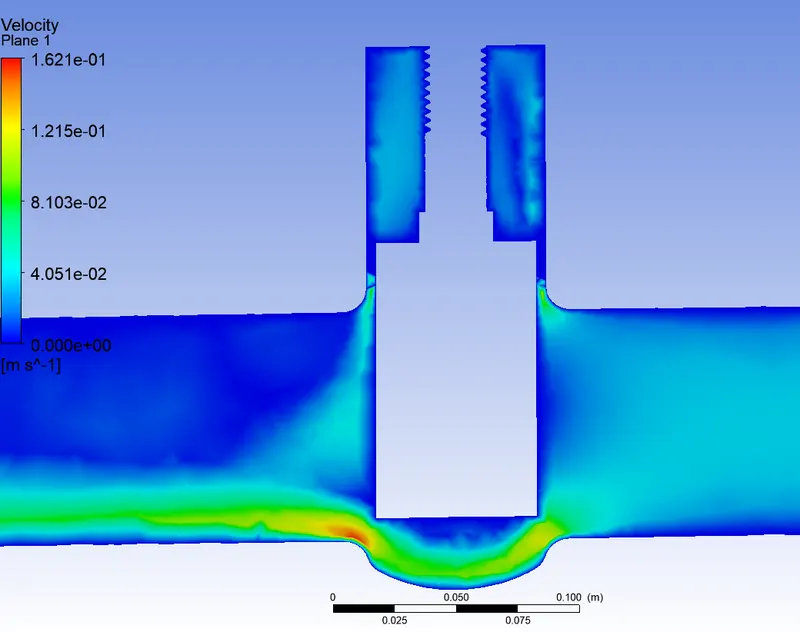
fig 11 valve open for 20 mm
mass flow rate -0.23173 and volume floe rate =-0.000213
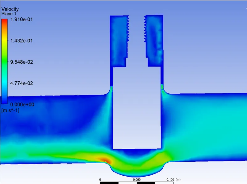
fig 12 valve open for 30 mm
mass flow rate -0.34823 and volume floe rate =0.000348
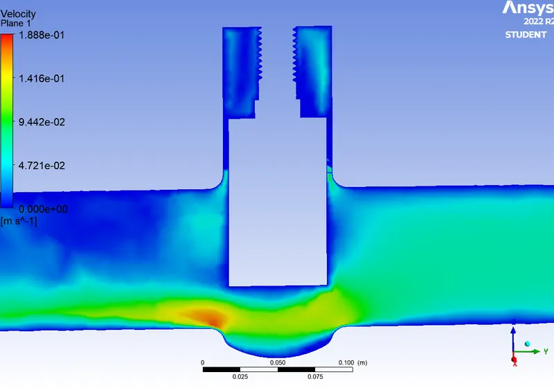
fig 13 valve open for 40 mm
mass flow rate -0.45614 and volume floe rate =0.000456
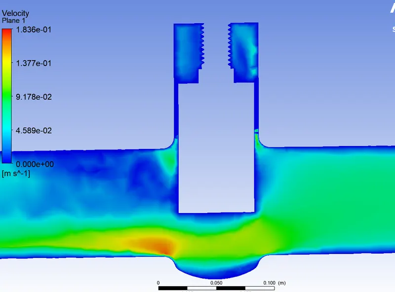
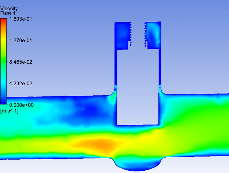
fig 14 valve open for 50 mm
mass flow rate -0.54159 and volume floe rate =0.000541
 i
i
fig 15 valve open for 62 mm
mass flow rate -0.65579and volume floe rate =0.000655
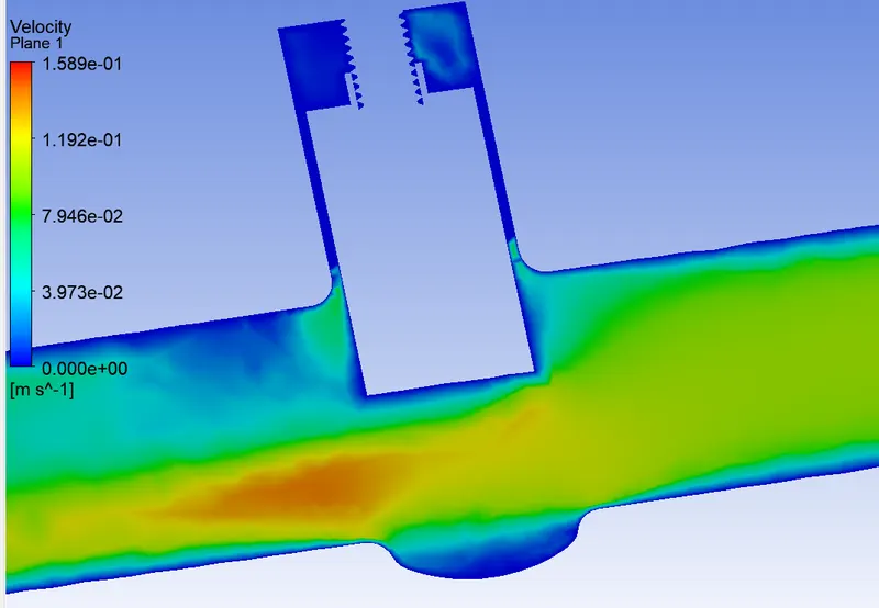
fig 16 valve open for 70 mm
mass flow rate -0.70324 and volume floe rate =0.000703
flow factor(k_v) and flow coeffient calculation(C_v)
The flow coefficient of a device is a relative measure of its efficiency at allowing fluid flow.
Flow Factor (Kv) is the flow coefficient in metric units that is defined as the flow rate in cubic meters per hour (m3/h)
`K_v=Q*sqrt((SG)/(deltaP)`
`C_v=K_v/0.865`
|
Sl no |
Gate open In mm |
Mass flow rate in kg/s |
Volume flow rate in m^3/s |
Kv |
Cv |
|
1 |
10 |
0.14374 |
0.000144 |
51.84 |
59.93 |
|
2 |
20 |
0.23173 |
0.000231 |
83.52 |
96.55 |
|
3 |
30 |
0.34823 |
0.000348 |
125.36 |
144.52 |
|
4 |
40 |
0.45614 |
0.000456 |
164.16 |
189.78 |
|
5 |
50 |
0.54159 |
0.000541 |
195.12 |
225.66 |
|
6 |
60 |
0.65579 |
0.000655 |
236.23 |
273.09 |
|
7 |
70 |
0.70324 |
0.000703 |
253 |
292.48 |
|
8 |
80 |
0.78652 |
0.000786 |
283 |
327.16 |
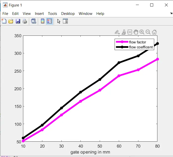
fig 17 flow factor, flow coeffiecent vs gate opening plot
conclusion
as the gate wall opens the mass flow rate at outlet increaase as well as volume flow rate aslo increase
due to presuure drop is same across the inlet and outlet same foe all simultaion so tha the flow factor and flow coeefient laso increases as the gate wall opens