Week 2 : Basic Calibration of Single cylinder SI-Engine
Aim: Basic Calibration of Single cylinder SI-Engine
objective:
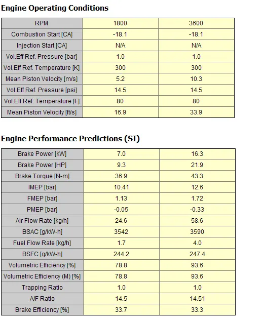
1.Run the case at 1800 rpm and list down important parameters
- air flow rate
- BMEP
- BSFC
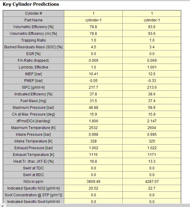
- In-cylinder pressure
2. Increase the power output at 3600 rpm by 10%
theory :
SI engine: An SI engine, or Spark Ignition engine, is a type of internal combustion engine that uses spark ignition to ignite the fuel-air mixture in the combustion chamber. The term "SI engine" is commonly used to refer to gasoline engines, as they use spark ignition to ignite gasoline fuel.
SI engines are widely used in a variety of applications, including automobiles, motorcycles, lawnmowers, and power generators. They are favored for their simplicity, reliability, and fuel efficiency, and are used in the majority of passenger cars and light trucks in the world.
working SI engine: its work on the otto cylcle principle. Where the fuel-air mixture is drawn into the cylinder during the intake stroke, and is compressed during the compression stroke. The spark plug is fired during the compression stroke, igniting the fuel-air mixture and creating a controlled explosion in the combustion chamber. This explosion drives the engine's pistons, which transmit power to the crankshaft, producing the engine's output power.
Mean effecative pressure:
Mean Effective Pressure (MEP) is a term used in internal combustion engine theory to describe the average pressure that is exerted on the engine's pistons during a complete cycle of engine operation. It is a measure of the engine's thermal efficiency and is used to calculate the engine's output power.
MEP is calculated as the ratio of the engine's power output to its displacement. The displacement of the engine is the total volume of air that the engine's cylinders can hold. The MEP can be calculated at any given engine speed, and is often used to compare the performance of different engines or to optimize engine design.
There are several different types of MEP
-
BMEP (Brake Mean Effective Pressure): BMEP is a measure of an internal combustion engine's average power output, calculated by dividing the engine's brake power output by its displacement. Brake power is the power produced by the engine at the crankshaft, before the loss of energy due to the drivetrain and other losses. BMEP is a measure of the average power an engine can produce over a given range of operating conditions.
-
IMEP (Indicated Mean Effective Pressure): IMEP is similar to BMEP, but it is calculated based on the engine's indicated power, which is the power produced by the engine before accounting for any frictional losses. IMEP is a measure of the engine's theoretical power output, and is typically used in engine design and optimization.
-
FMEP (Friction Mean Effective Pressure): FMEP is the difference between IMEP and BMEP, and represents the power loss due to friction in the engine. FMEP is a measure of the engine's frictional losses, and is used to evaluate the engine's efficiency and identify areas for improvement.
-
PMEP (Pumping Mean Effective Pressure): PMEP is a measure of an engine's pumping losses, which are the losses due to the engine's air pump. PMEP is calculated by subtracting the pumping losses from the BMEP, and represents the engine's effective power output after accounting for pumping losses. PMEP is used to evaluate engine efficiency and to identify areas for improvement in the engine's air pumping system.
BMEP = IMEP - FMEP - PMEP
case setup:
open gt power application from tutorials copy si engine tutorials
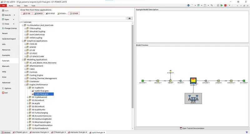
si engine consistes of many componets which an be seen in the tutoarila file now save the file to a different folder otherwise the simulation wont run
after saving file to different location the simulation parameter can be adjusted and run the simulation
now look in to setup to achive the objective
envirimental inlet and outlet : the setup is simple here atmospharic air is imported and the exhoust gases are emmited at atmopheric pressure
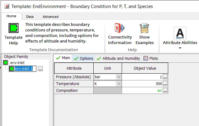
lets keep the intake runner and exhaust runner same as it is
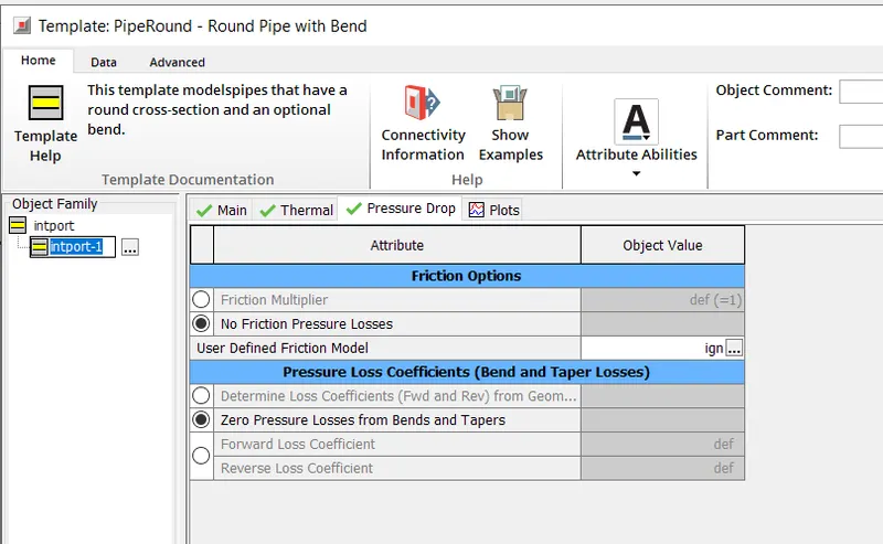
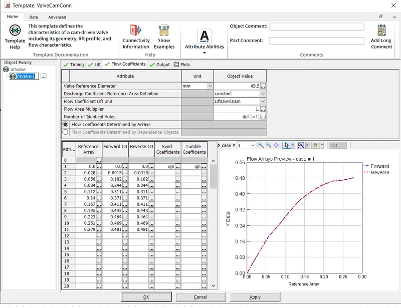
in intake port and exhaust port the pressure pressure drop due to friction selcted as no because in valves these losses are acummedated using flow coeefients
air fuel mixture is injected by InjAFSeqConn (This template is used for the operation of a sequential pulse fuel injector, most commonly in SI engines.)
here injector delivary rate is 6g/s and air fuel ratio is 14.5
inlet valve and outlet valve:enter valve opening angle lift parameters and flow coeffient
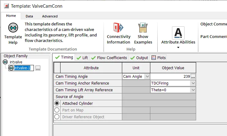
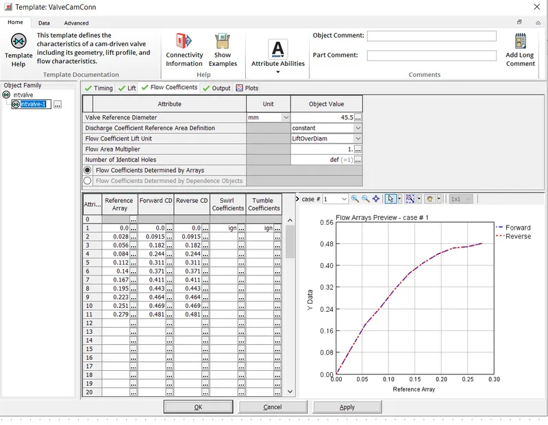
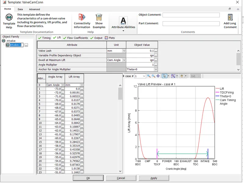
in cylinder
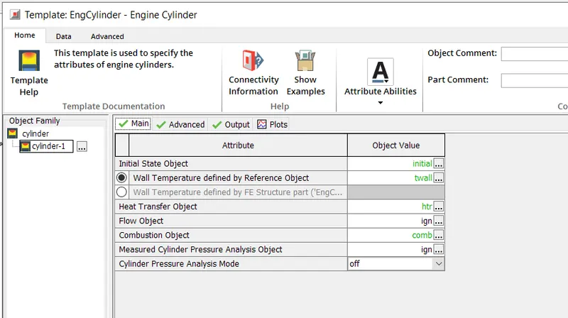
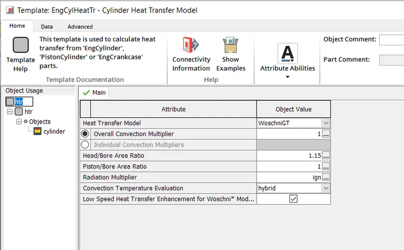
heat transfer object: need to define which model is using
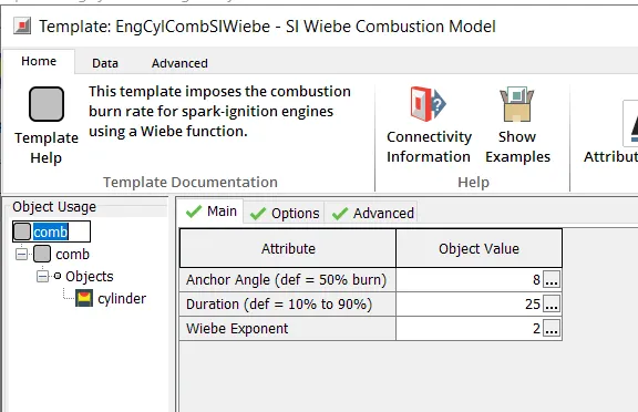
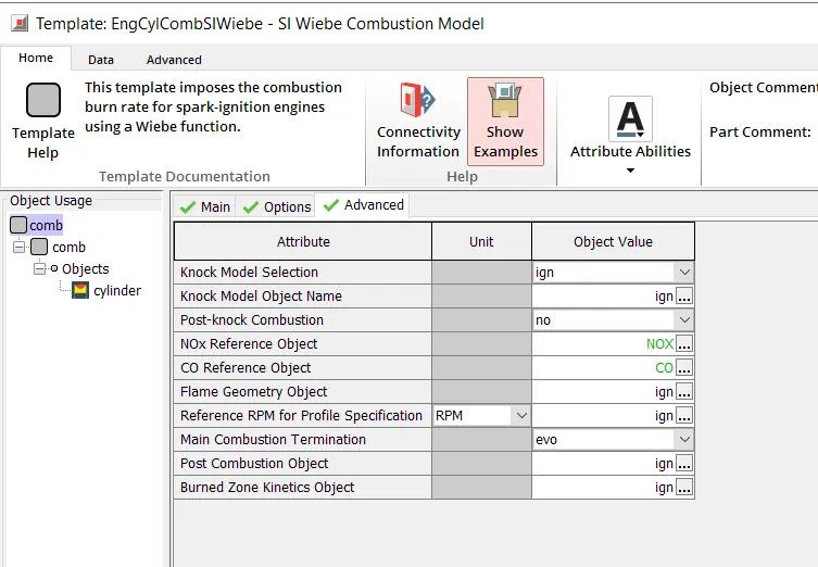
combustion object: in cunstion activate NOX and CO emmision
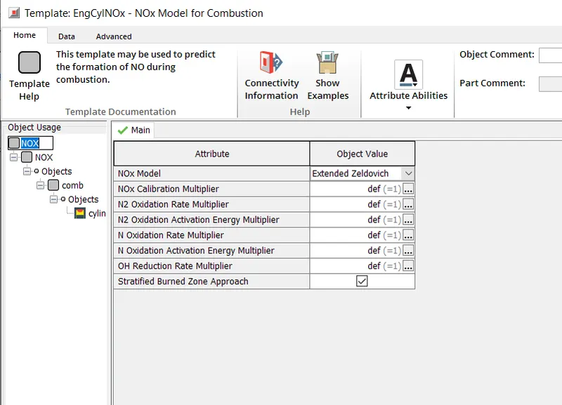
NOX object:select the model
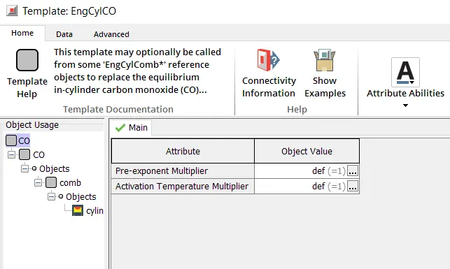
CO object
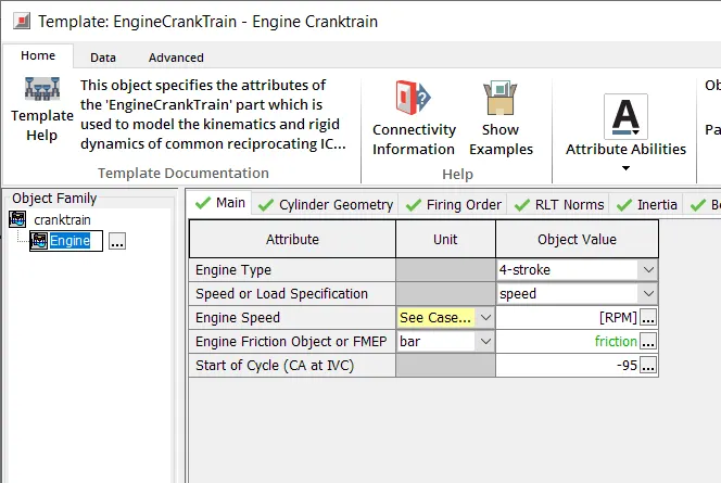
egine setup
define type of engine select specification as spped and in engine speed create a object named [RMP] to run multiple case at time
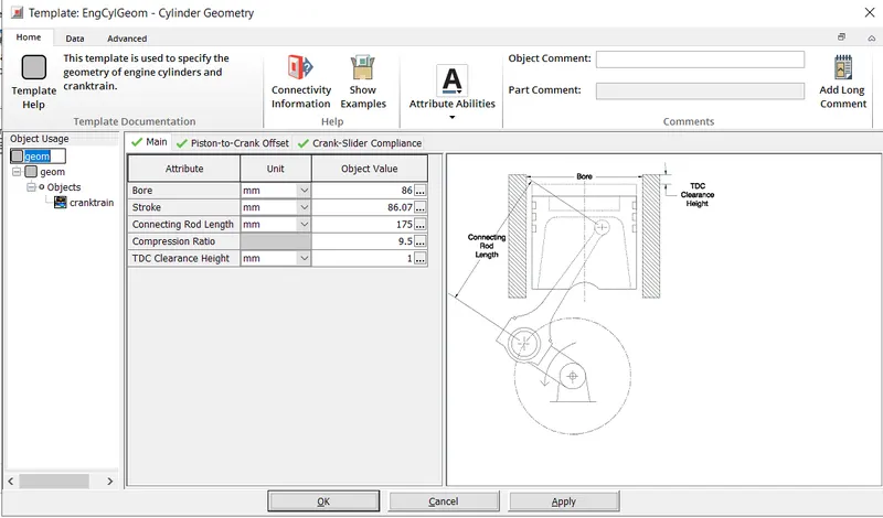
cylinder grometry
after all set up now case setup
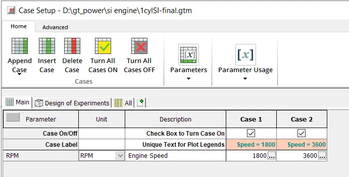
now run with 2 cases at differnt engine speed
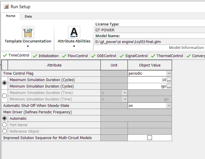
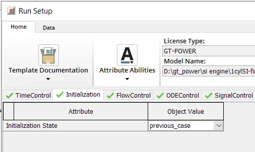
run setup
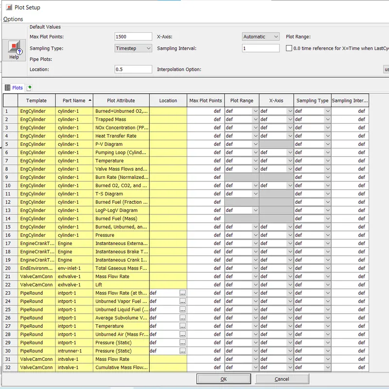
plot setup :different type of results plot saaved after simulation
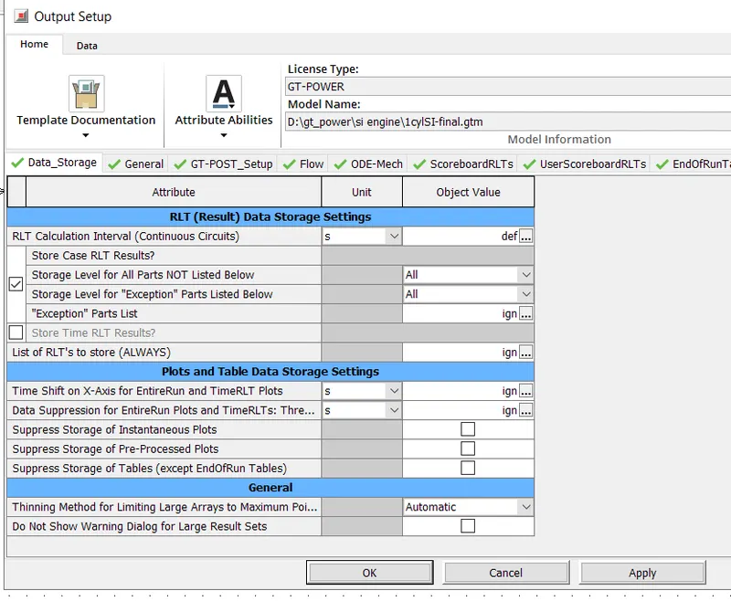
output setup
after all set up run the simulation
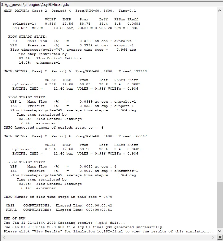
after simulation runs view the results
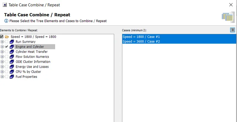
to see all case results at atime go to macros section and select combine table data select all case and apply
Results:
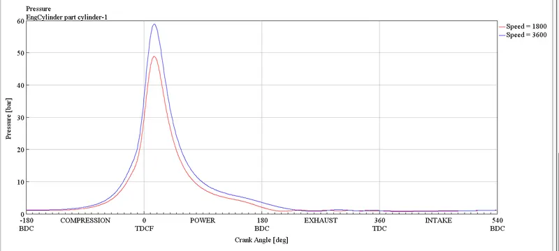
cylinder pressure
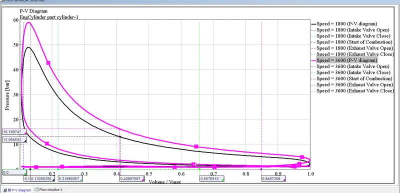
pv diagram
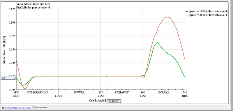
mass plow rrate at inlet valve
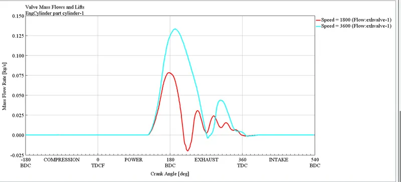
mass flow rate at outlet
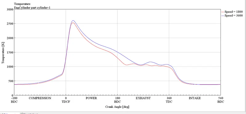
temprature
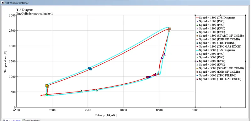
ts diagram
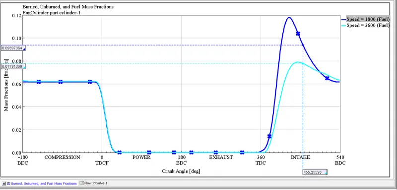
unburt fule mass fraction
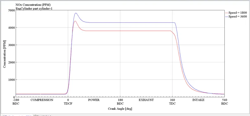
NOX
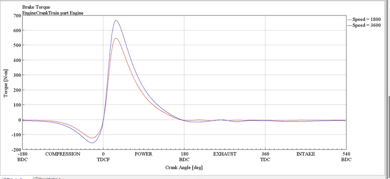
brake torque
BMEP = IMEP - FMEP - PMEP
for 1800 RPM
BMEP=10.41-1.13-(-0.05)=9.33 bar
for 3600 RPM
BMEP=12.6-1.72-(-0.33)=11.21 bar
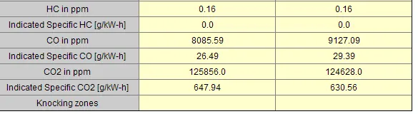
comclusion: from results it can be seeen that with increasing speed will increase the perpormence of engine mean effective pressure of engine, air fuel rate, BSFC, volumetric efficiency
with that there are some draw back also there increasing concetration of NOX and CO
PROBLEM 2
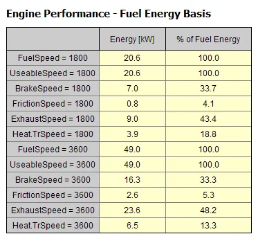
At current 3600 RPM speed the enine produce a 16.3 Kw power
To improve the power output of a spark-ignition (SI) engine at constant speed, several strategies can be employed:
-
Increasing engine displacement: Larger engines can generate more power, but at the cost of added weight and decreased fuel efficiency.
-
Improving engine efficiency: Making modifications to the engine such as adding a turbocharger or improving the intake system can increase engine efficiency and power output.
-
Increasing the compression ratio: A higher compression ratio allows for more efficient combustion, which can result in increased power output.
-
Upgrading the fuel system: Using higher-octane fuel or upgrading the fuel delivery system can improve combustion and increase power output.
-
Upgrading the ignition system: An improved ignition system can allow for more complete combustion, resulting in increased power output.
here we are going to increase the stroke length and make air fuel mixture richer and see the results
case setup
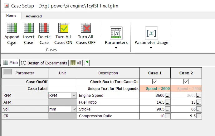
results of problem 2
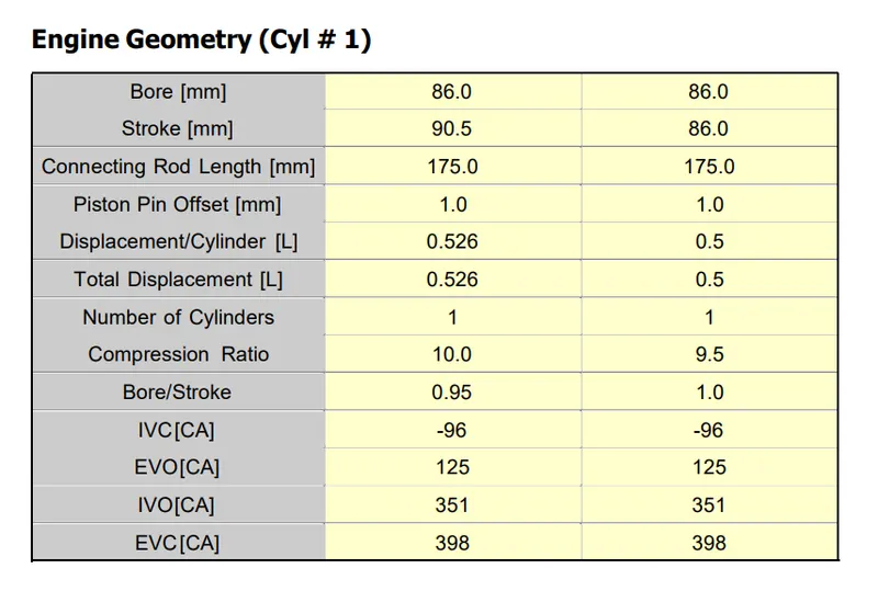
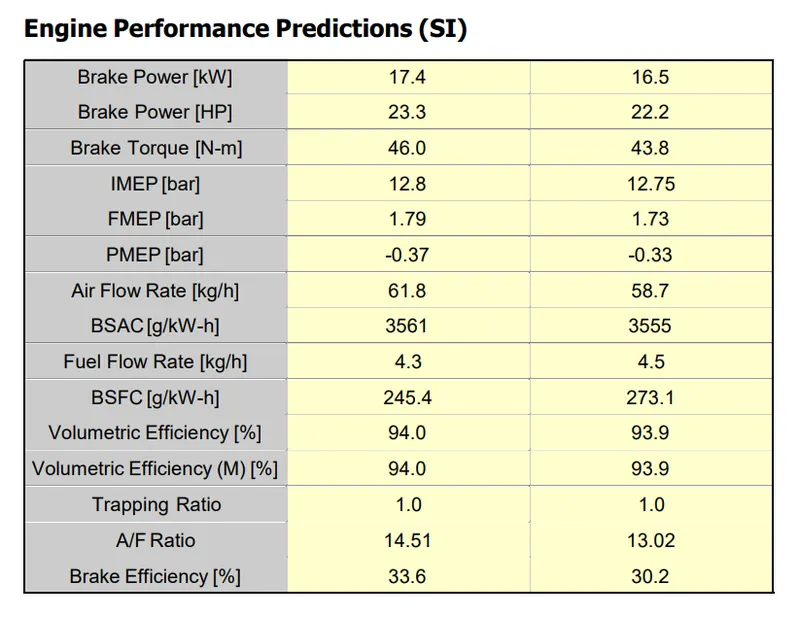
engine propormence
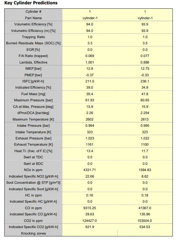
from results of problem 2 it can be seen that making air fuel mixture riched doesnt help much in performence but it will inrease the CO emmision drastically hence using rich air fuel mixture id a bad idea
with increasing stroke length there id a good improvement in performence and also sligth improvement in BMEP