Week 9: Project 1 - Surface preparation and Boundary Flagging (PFI)
aim: Surface preparation and Boundary Flagging (PFI)
objective;
1, Boundary Flagging.
2, Surface preparartion.
NO HYDRO case set up, create an animation for NO HYDRO simulation
theory:
A spark-ignition engine (SI engine) is an internal combustion engine, generally a petrol engine, where the combustion process of the air-fuel mixture is ignited by a spark from a spark plug.
A four-stroke spark-ignition engine is an Otto cycle engine. It consists of following four strokes: suction or intake stroke, compression stroke, expansion or power stroke, exhaust stroke. Each stroke consists of 180-degree rotation of crankshaft rotation and hence a four-stroke cycle is completed through 720 degrees of crank rotation. Thus, for one complete cycle there is only one power stroke while the crankshaft turns by two OR MORE revolutions
The otto cycle processes are described by
- Process 0–1 a mass of air is drawn into piston/cylinder arrangement at constant pressure.
- Process 1–2 is an adiabatic (isentropic) compression of the charge as the piston moves from bottom dead center (BDC) to top dead center (TDC).
- Process 2–3 is a constant-volume heat transfer to the working gas from an external source while the piston is at top dead center. This process is intended to represent the ignition of the fuel-air mixture and the subsequent rapid burning.
- Process 3–4 is an adiabatic (isentropic) expansion (power stroke).
- Process 4–1 completes the cycle by a constant-volume process in which heat is rejected from the air while the piston is at bottom dead center.
- Process 1–0 the mass of air is released to the atmosphere in a constant pressure process.
The Otto cycle consists of isentropic compression, heat addition at constant volume, isentropic expansion, and rejection of heat at constant volume. In the case of a four-stroke Otto cycle, technically there are two additional processes: one for the exhaust of waste heat and combustion products at constant pressure (isobaric), and one for the intake of cool oxygen-rich air also at constant pressure; however, these are often omitted in a simplified analysis. Even though those two processes are critical to the functioning of a real engine, wherein the details of heat transfer and combustion chemistry are relevant, for the simplified analysis of the thermodynamic cycle, it is more convenient to assume that all of the waste-heat is removed during a single volume change.
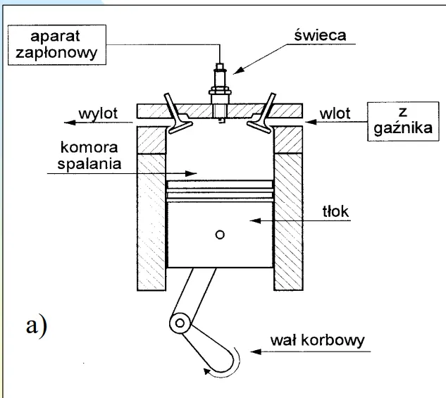
engine scheme
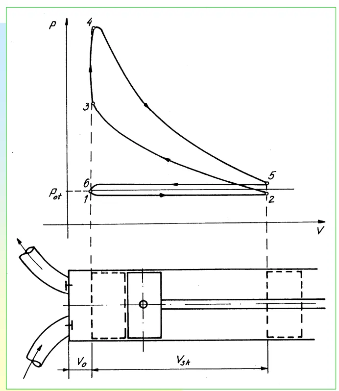
otto cycle operation graph
case set up:
intially the give stl file is imported to the converge workspce when the file is run diagnosis the will be error present the removng error is known as surface preparation and given a name to each part is boundary flagging
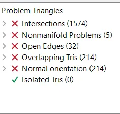
intial diagnosis run
the are many error present in this file due to this need to resolve these error sothat continue with case setup
before try to resolve thse error we need to boundary flag these this will make surfca prepration easy
so first boundary flag
boundary flag
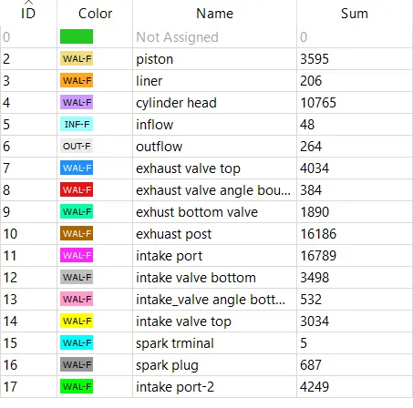
these are theboundary flagging
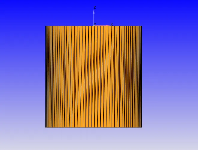
liner
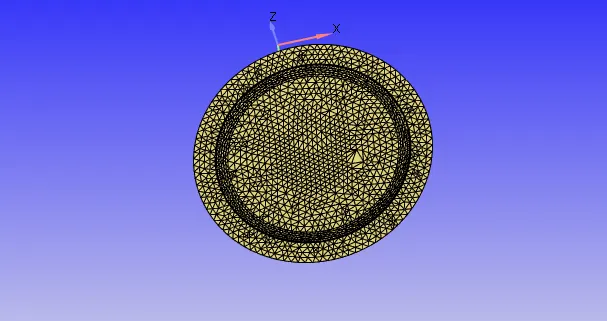
piston
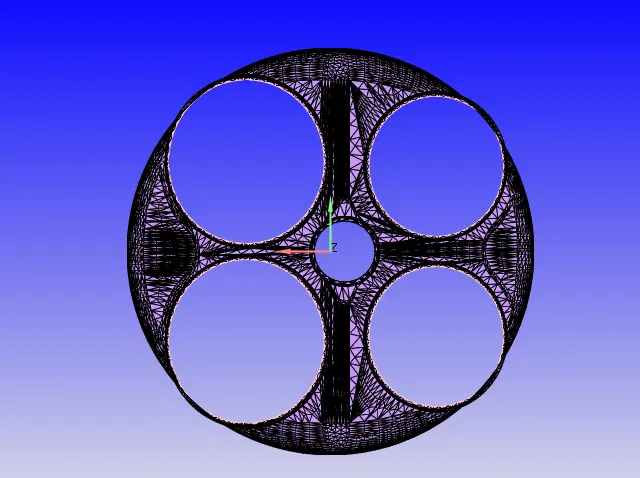
cylinder head
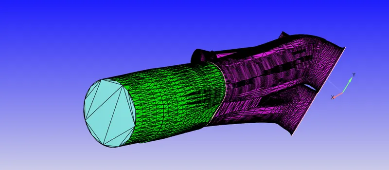
inflow, intake port 1 and 2
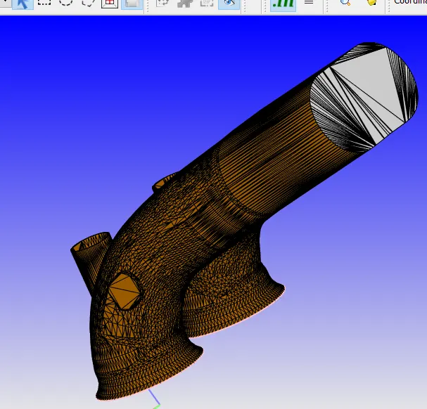
outflow and exhuast port
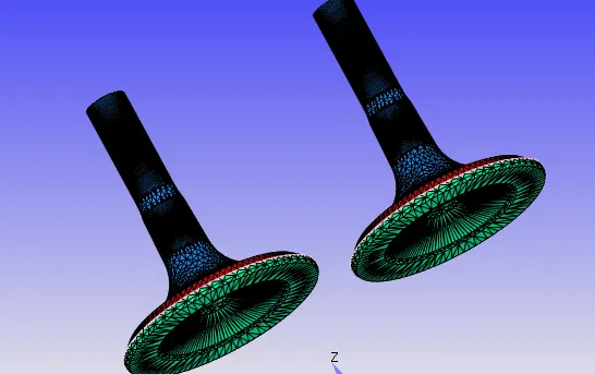
exhast valve top, angle boundaries and bottom
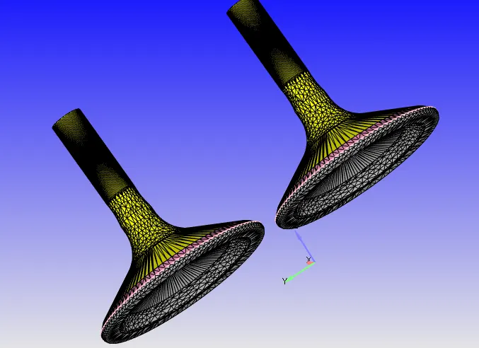
inlet valve top, angle boundaries and bottom
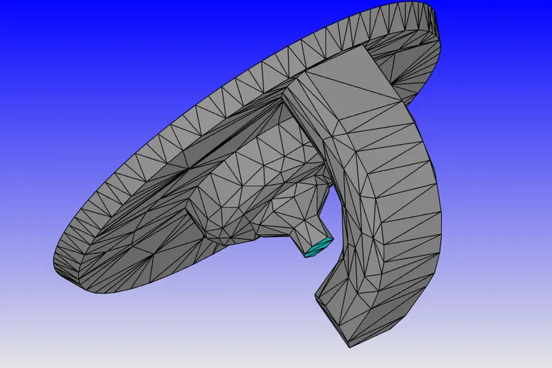
spark plug and terminal
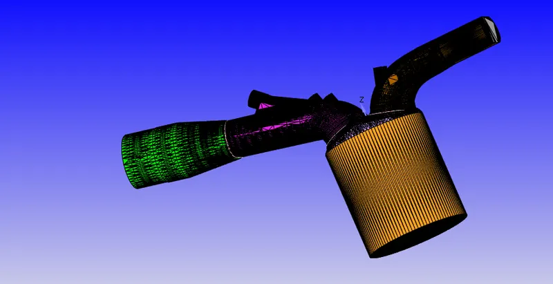
full engineover view
surface preparation
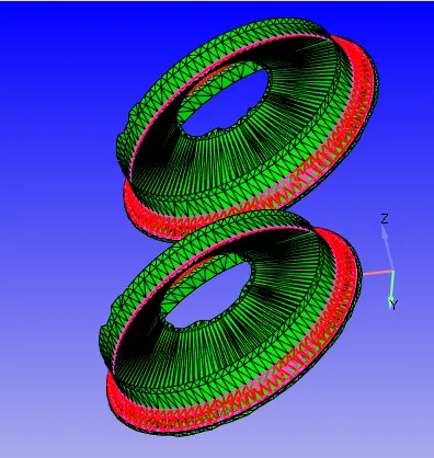
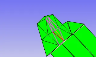
these are the intersection error at inlet post and inlet valve
thse can be resolve by translatiing down the valve by few mm
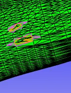
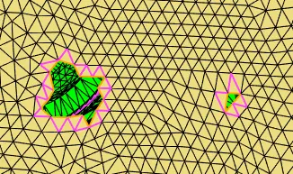
these are the open edges
relved by using patch commnda
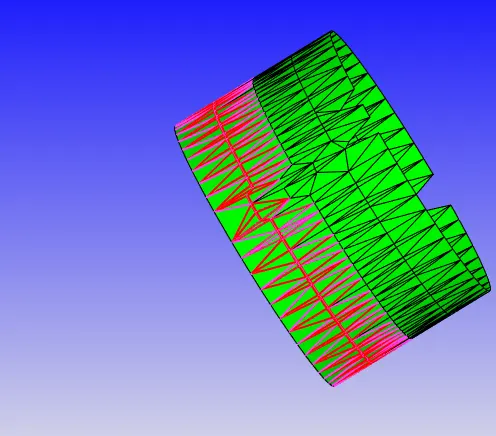
normal oreintation error
thse can be resoved by using tranformation commnand
after recifing error run diagnossis again if any error present try to resolve according to the problem
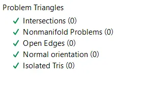
after no error in diagnosis now case setup
case setup
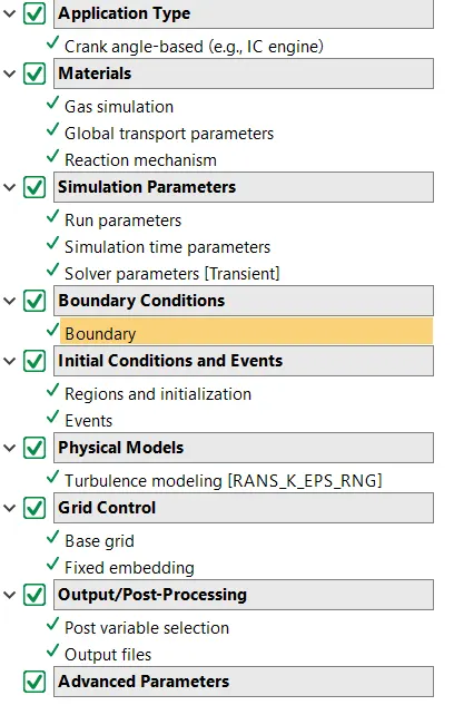
case set up tree
application type:
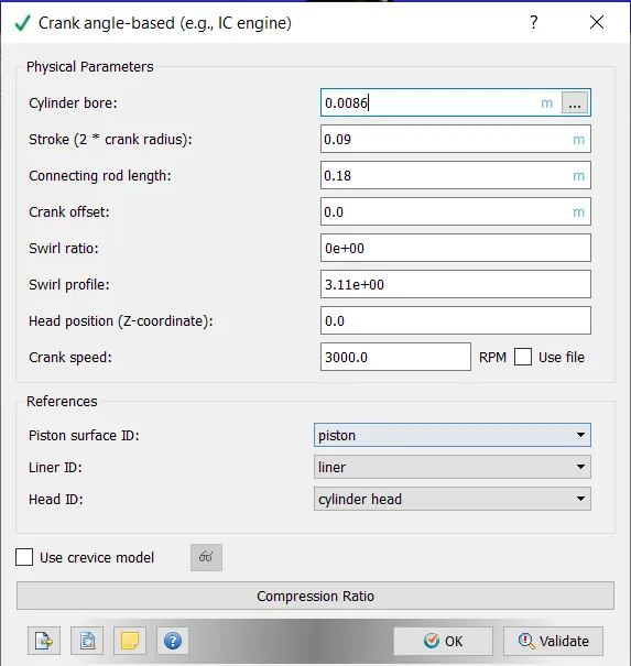
materials:
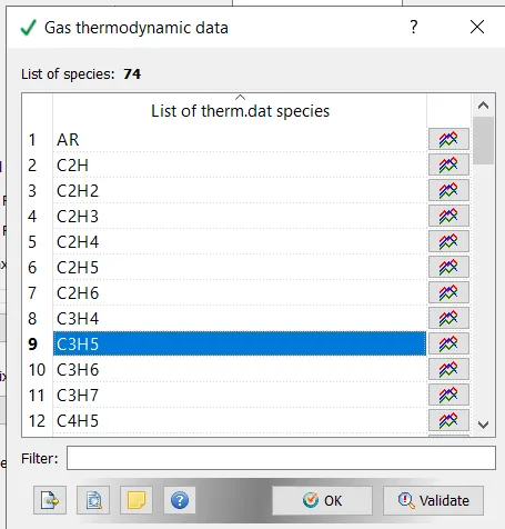
in gas simlation import thermodynamic data provide in gas thermodynamic section and upload
them.dat
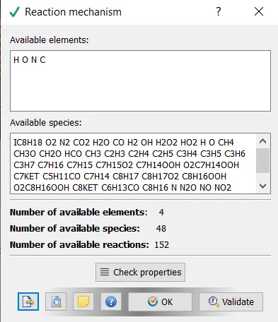
in rection mechanism import mech.dat file and validate
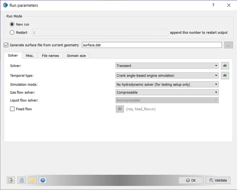
simulation parameter;
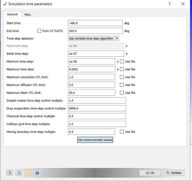
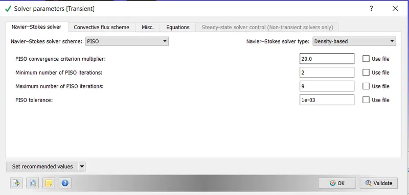
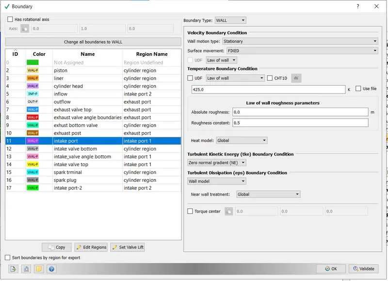
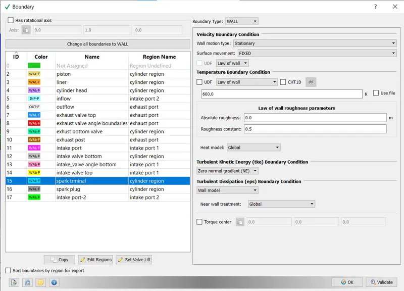
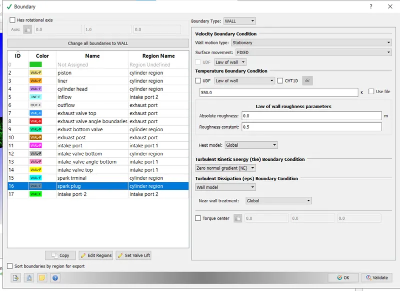
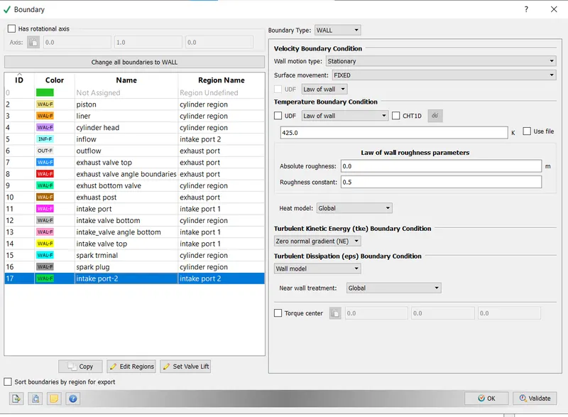
boundaries:
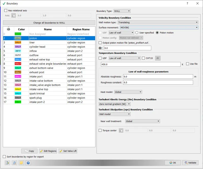
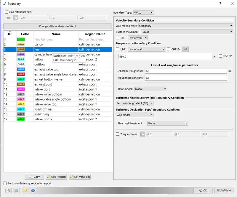
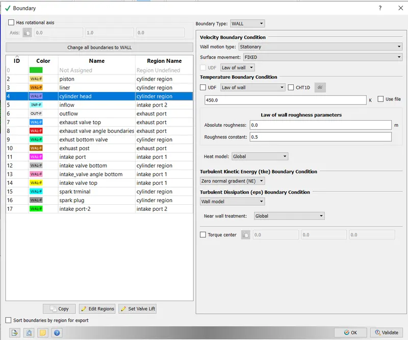
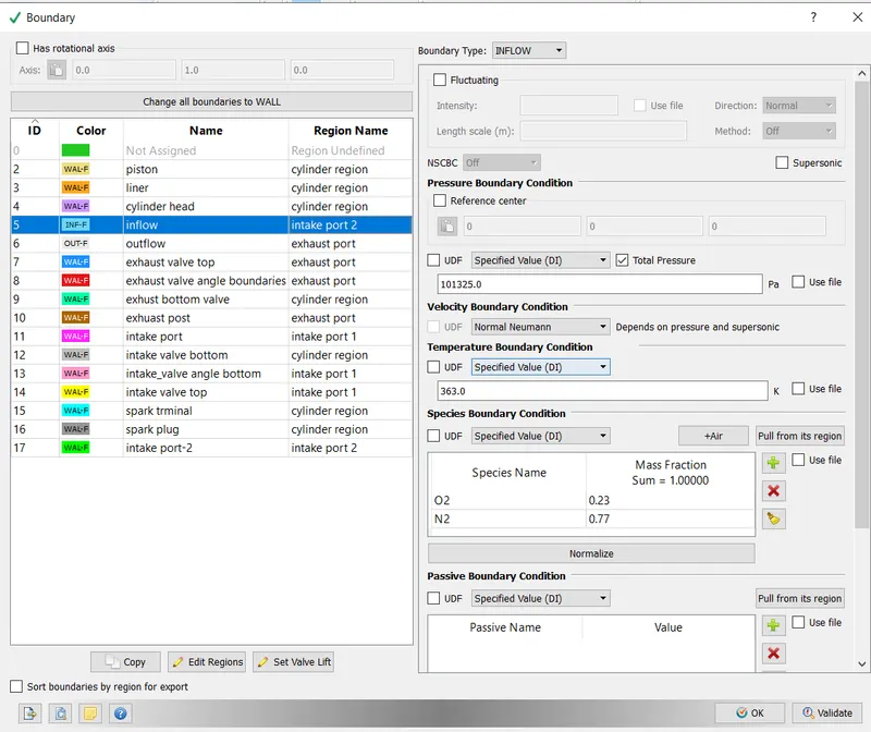
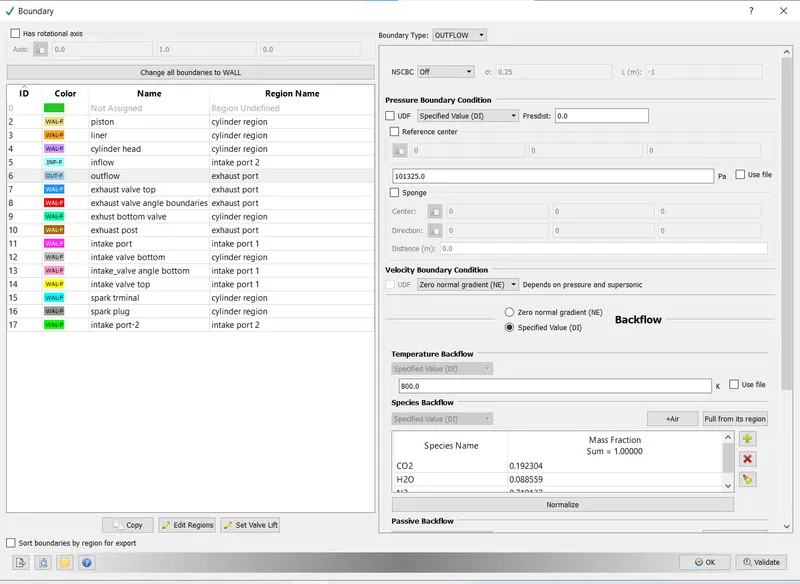
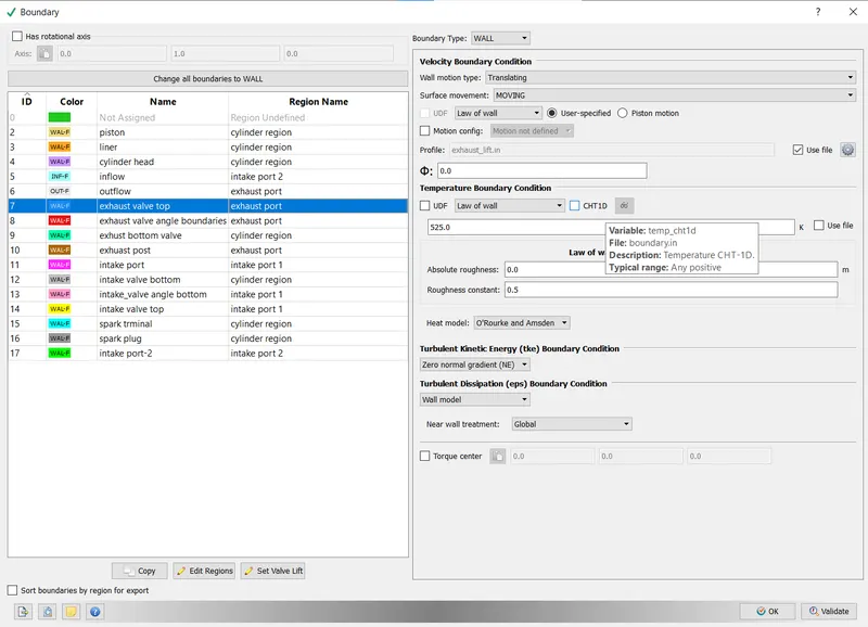
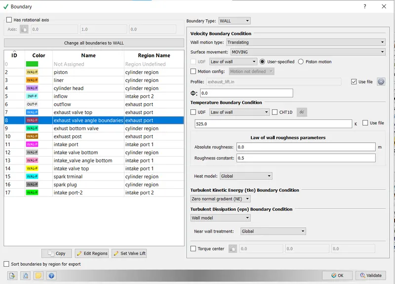
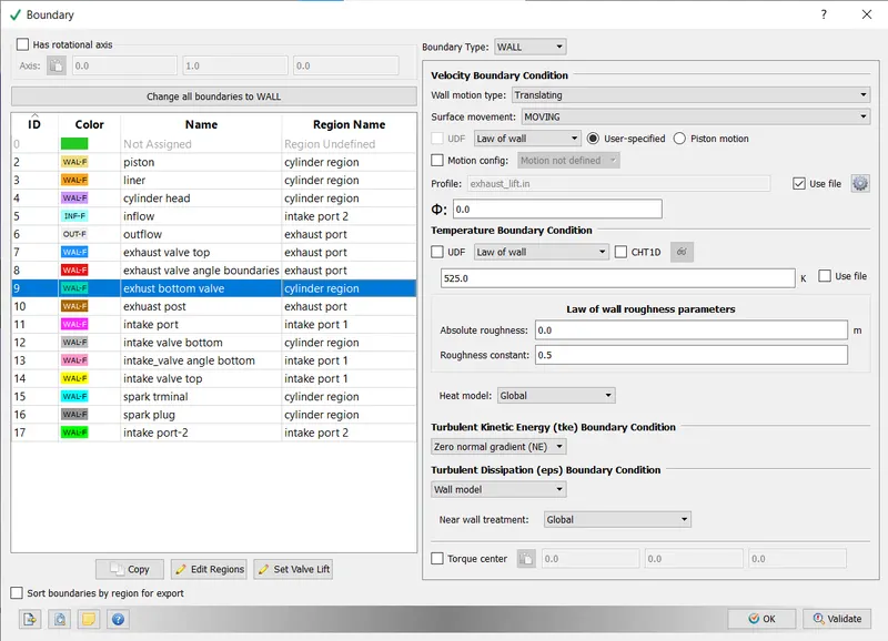
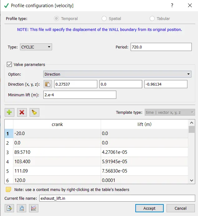
the valve movement pattren is uploaded using intake lift file and simmilarly done for exhast wall also
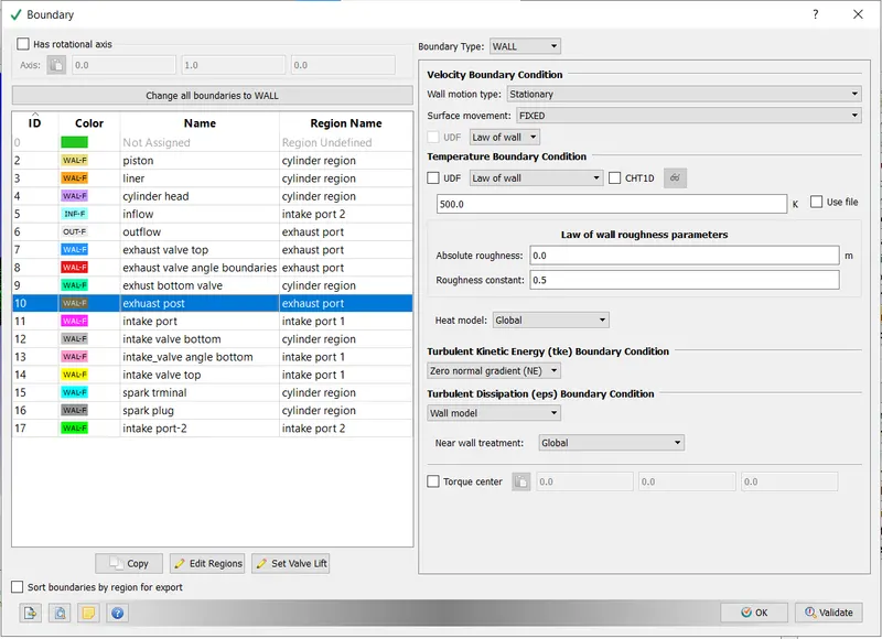
intial condtion and events:
in region and intialization 4 region is defined
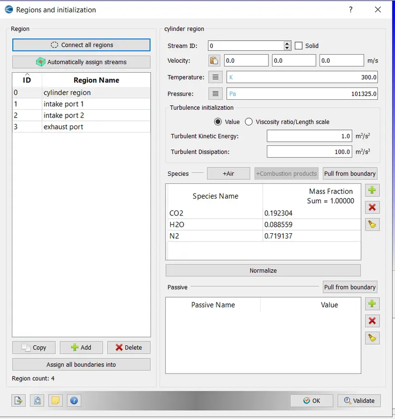
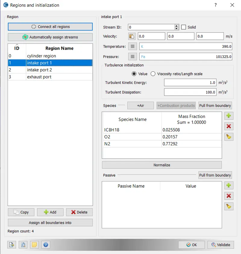
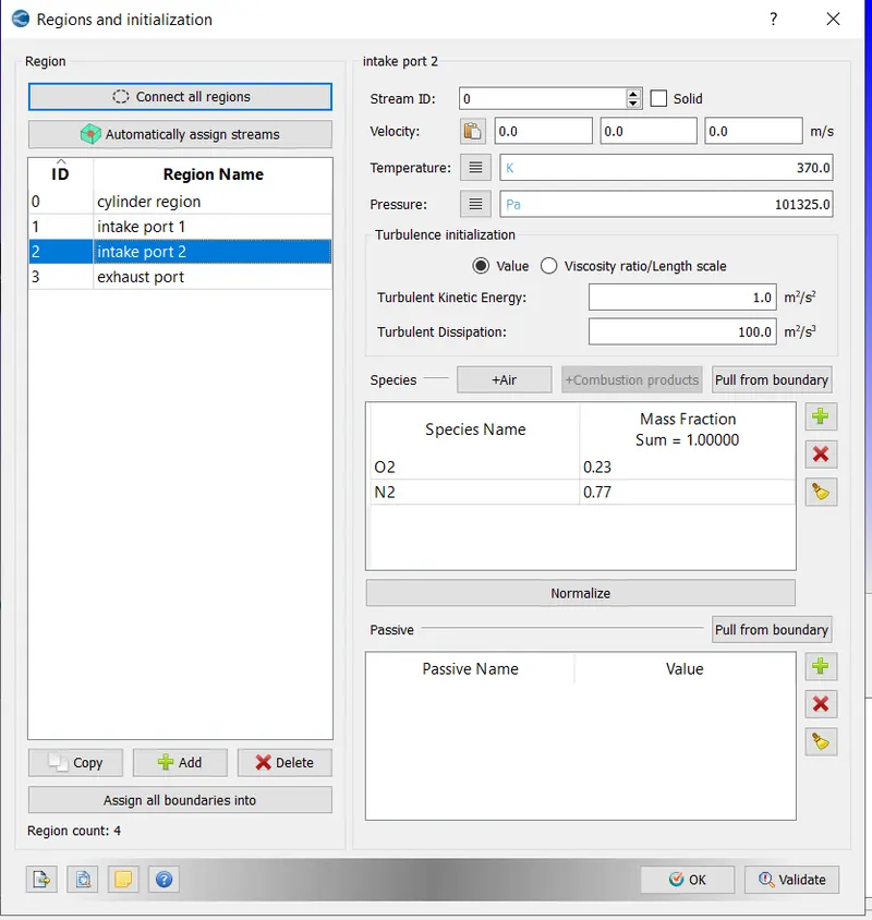
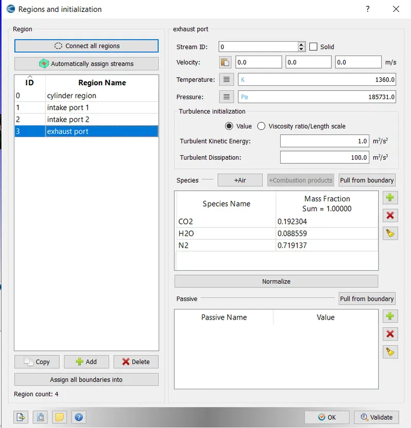
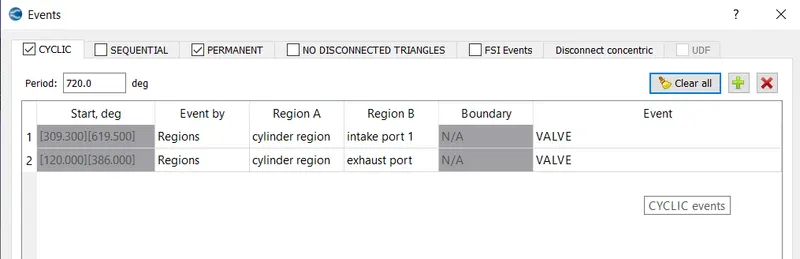
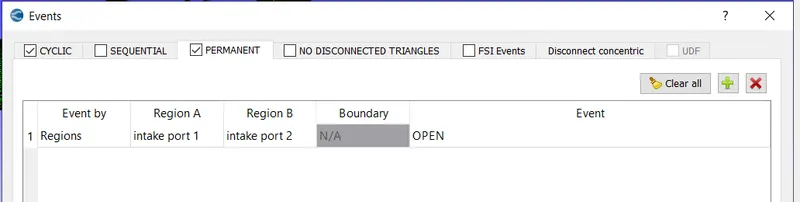
events:
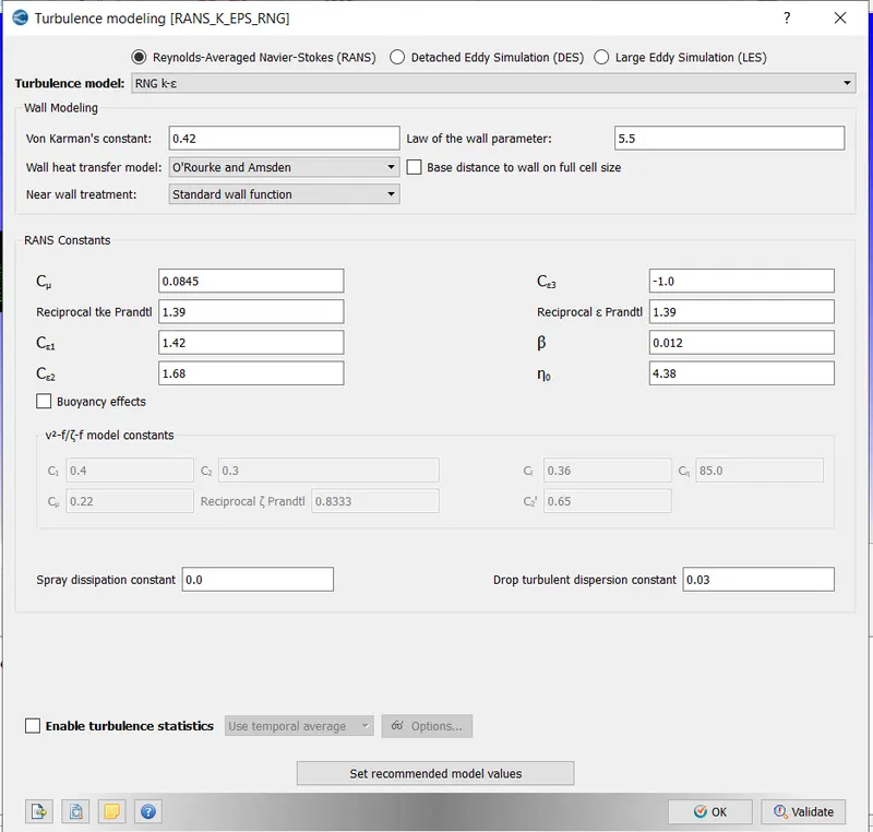
physical model
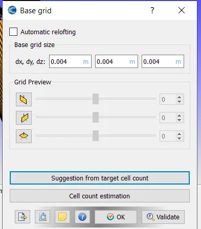
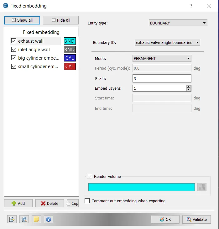
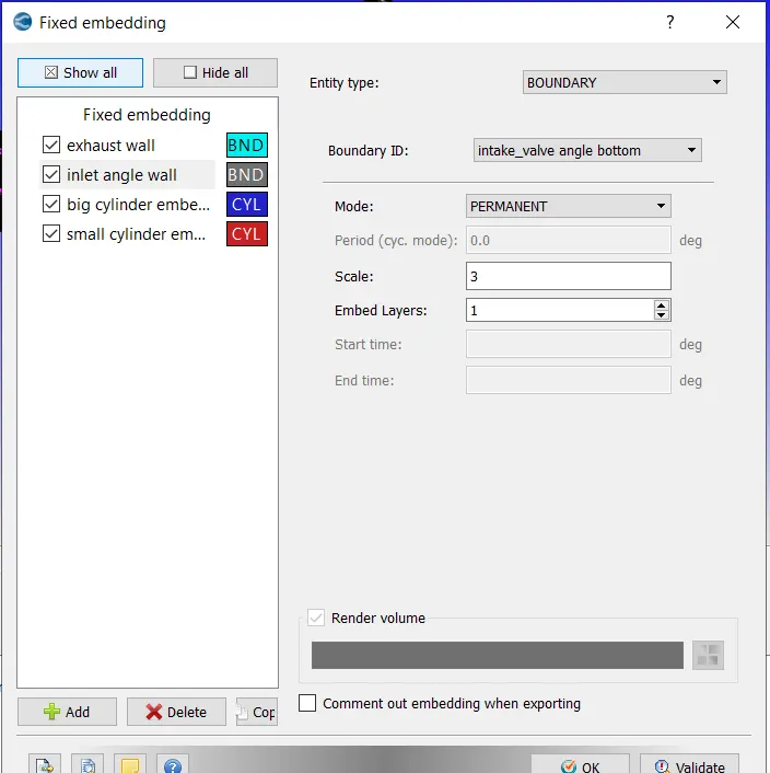
GRID CONTROL
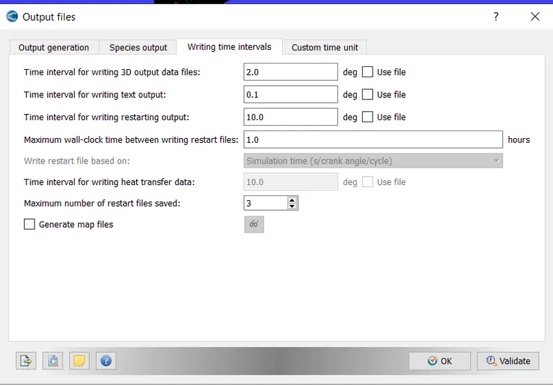
otput/post processsing
after case set up
run final validation
save the file and export the inputfile to a folder
open cygwin and navigate to folder and run this code
mpiexec.exe -n 2 converge.exe restricted
wait till simulation runs and post process the result
result:
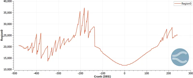
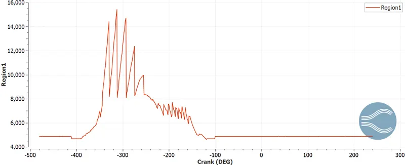
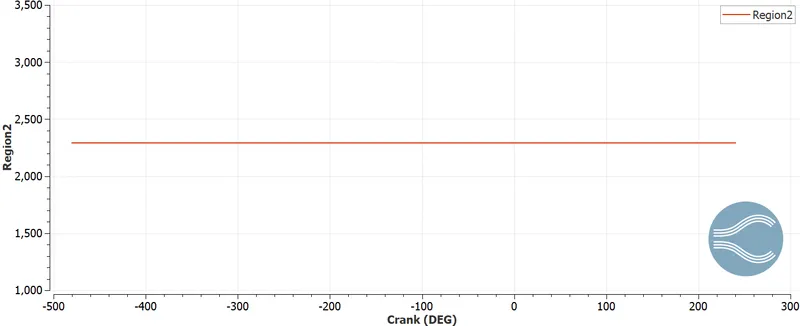
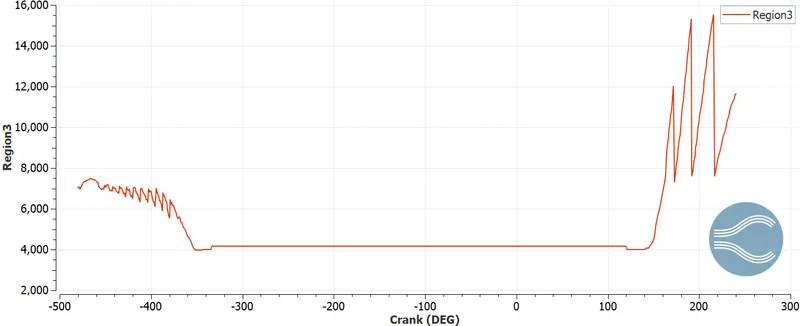
cell count by region
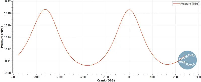
pressure
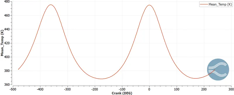
temp
because this is no hydro simulation this results do not match with the otto cycle results
post processing:
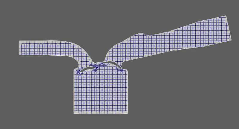 \
\
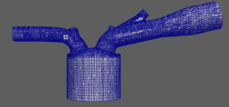
meshing
animation of cycle
https://drive.google.com/file/d/1UbYLrJlhOxcUnIlH0TeGDISqKzN63_RZ/view?usp=sharing
conclusion:
from animation it can be seen that it replicating the otto cycle so thata it can be said that the result is close to actual otto cycle