Week 3 - External flow simulation over an Ahmed body.
Challenge 3
Aim: simulation of External flow simulation over an Ahmed body.
Objective: Run the simulation for the velocity of 25 m/sec with the default air properties in fluent.
Introduction:
Ahmed’s body: -it is simplified vehicle model the airflow around the Ahmed body captures the essential flow features around an automobile and was first defined and characterized in the experimental work of Ahmed
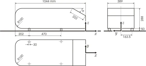
Fig 1 Ahmed body geometry
Although it has a very simple shape, Ahmed body allows us to capture characteristic features that are relevant to bodies in the automobile industry.
Application of ahmed body
its simplified vehicle model its easy to construct and simulate to get close results.
point of separation:-
The separation point is the point where the air stops "sticking" to an object that is moving through the air.
solving and modelling approach
Geometry:
Ahmed body is imported in to space claim for basic simulation just prepare a encloser using encloser command from prepare section once the encloser is created then suppress to physics the ahmed body and close the spaceclaim application
For refined mesh geometry to get finer mesh another encloser is created then application is closed
Mesh
Open mesh application name selection is done for inlet outlet, car walls, and symmetry walls. For basic mesh just mesh the available model for 100 mm for whole body then application is closed
For fine mesh body sizing added to inner encloser and multizone method is applied for outer encloser, face sizing done for car wall and foots of car and inflation layer id added o car wall for k – epsilon method 0.17mm first layer and for k omega 0.0117mm which is calculated using Y+15 and y+1 respectively
Y+ calculation
for y+=1
Renolds number
`Re=(rho*u*D)/mu`
D is charecterstics length =A/P
A= area
P = perimeter
Re=(1.225*25*1.36)/(1.789*10^-5)
RE=100000
friction coeffient
`C_f=0.026/(Re)^(1/7)`
C_f=0.005
wall shear stress
`tau_w=0.5*C_f*rho*u^2`
`tau_w=1.912`
shea velocity
`U_f=sqrt(tau_w/rho)`
U_f=1.2524
Y+=1
first layer thickness
`deltaS=(Y^+*mu)/(U_f*rho)`
`deltaS=0.0117`
Y+=15
`deltaS=(Y^+*mu)/(U_f*rho)`
`deltaS=0.17`
Then generate the mesh once mesh generation is done close meshing application
Setup
Open fluent Check for mesh quality then select solver setup
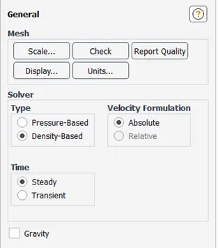
Fig 2 solver set up
- Selection of viscus model k epsilon and k omega model used
- Boundary conditions inlet velocity as 25 m/s
- In solution create definition report and plot for drag coeffect
- Create a plane inside simulation model to see the velocity and pressure profile over the ahmed body
- Create contour for velocity on plane and pressure contour on same plane and a pressure contour on car wall to create animation
- Animation created using 3 contours
- Initialize the solution and calculate solution for 1000 iteration
- Calculation is done create animation video
Results
Basic simulation
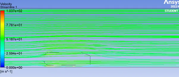
Fig 3 velocity streamline
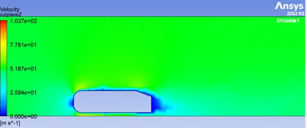
Fig 4 velocity contour on cut plane
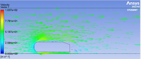
Fig 5 velocity vector
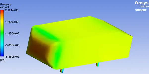
Fig 6 pressure on car walls
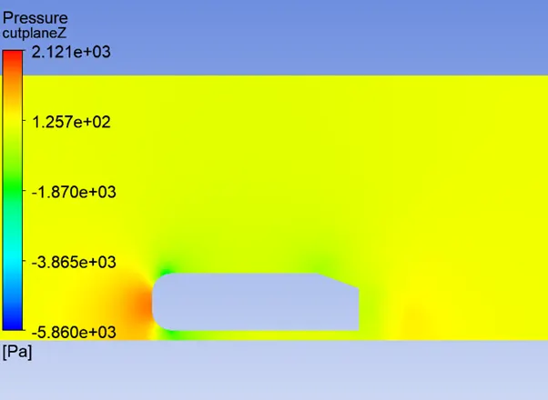
Fig 7 pressure on cut plane
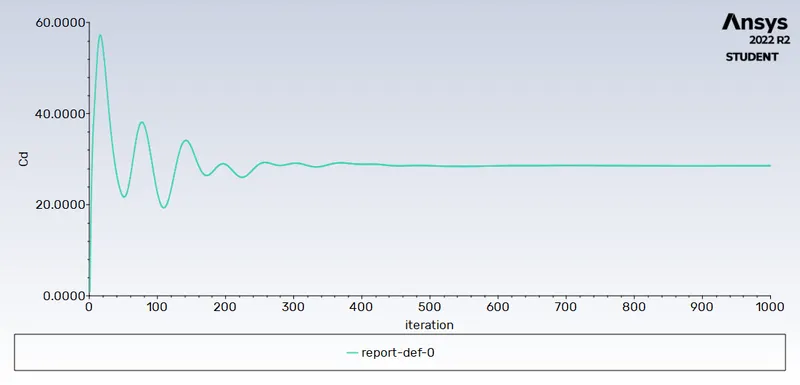
drag force coeffient
K omega model results
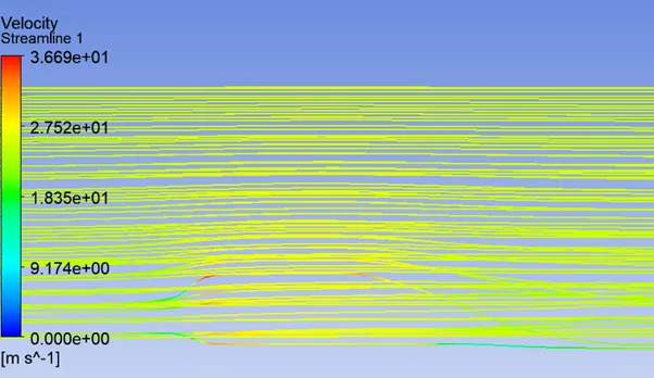
Fig 8 velocity streamline
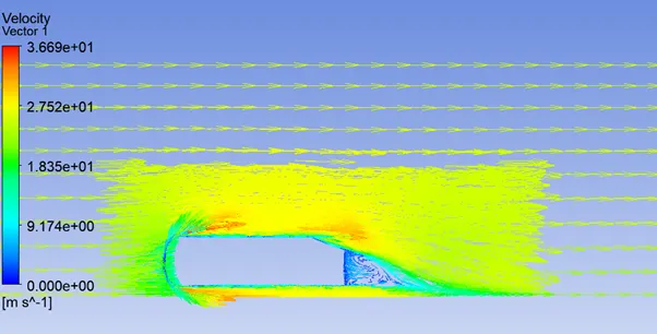
Fig 9 velocity vector
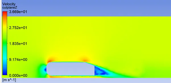
Fig 10 velocity contour on cutplane
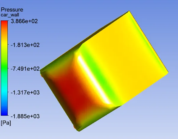
Fug 11 pressure on car wall
fig 12 pressure contour on cut wall
K epsilon model results
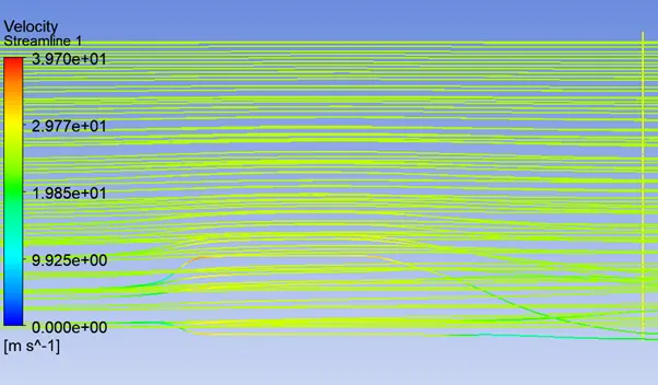
Fig 13 velocity streamline
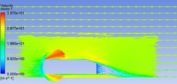
Fig 14 velocity vector
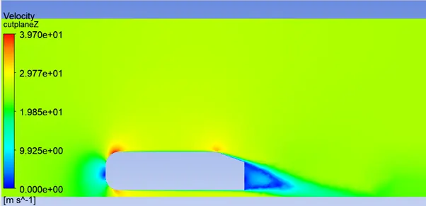
Fig 15 velocity contour on cut plane
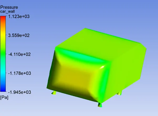
Fig 16 pressure on car wall
Conclusion
As the mesh is get fine the velocity and pressure profile looks great
results animation are uploaded in zip file
Negative pressure in the wake region.
The flow behind an object separates from the surface and creates a highly turbulent region behind the object, called the wake. . The pressure inside the wake region remains low as the flow separates and a net pressure force (pressure drag) is produced. In other words, due to the production of pressure drag being produced from flow separation, the pressure in the wake region is low. This is what is causing the vacuum.