Week 3: Flow over a backward facing step
Challenge 3
Aim Flow over a backward facing step
Objective:
run the case for three different base mesh sizes
- dx = dy = dz =2e-3m
- dx = dy = dz =1.5e-3m
- dx = dy = dz =1.0e-3m
introduction:
Backward Facing Step (BFS) problem is one of the intriguing problems in the field of Turbulence Fluid Dynamics. In this problem, the flow enters from the inlet passes through a constant area duct and exits into another duct having a cross-sectional area larger than the inlet duct. As this occurs, a recirculation zone occurs at the 'step’ of the duct having a larger cross-sectional area. Even though it is a simple and a common problem but it has a wide scope which makes it a building block for a variety of applications.
Theory
The Backward-Facing Step (BFS) flows, also called as “sudden expansion flows”, “circular expanding flow”, “back-step flow”, “diverging channel” or “backward flow” under some other occasions, involves the basic features of general separation flows. It has three-dimensional nature and suitable for two-dimensional discussions under some flow conditions and/or with simple step geometry. It is an important model for separation flows across wide range of Reynolds numbers. This section describes the features and major theoretical challenges in BFS flows.
Backward-Facing Step (BFS) flow is one representative separation flow model, which is of significance in both theoretical and engineering development. Various applications for BFS flow can be found in our daily life, such as the air foils at large attack angle, the spoiler flows, separation flow behind a vehicle, inlet tunnel flow of engine.
It is a basic model that involves the most important features of a separated flow: free shear flow separation, vortex evolution and re-attachment. As is well known that the flow separation near the BFS will possibly lead to additional flow resistance and noise, and under critical conditions even for stalling of an aircraft, the general understanding of the physics in BFS flow has become one hot topic in recent years.
In addition, for some other applications such as mixing chamber or combustors, effective mixing is preferred and can be designed with detailed BFS geometric considerations, which also leads to the study of various mechanism and controlling studies in this field.
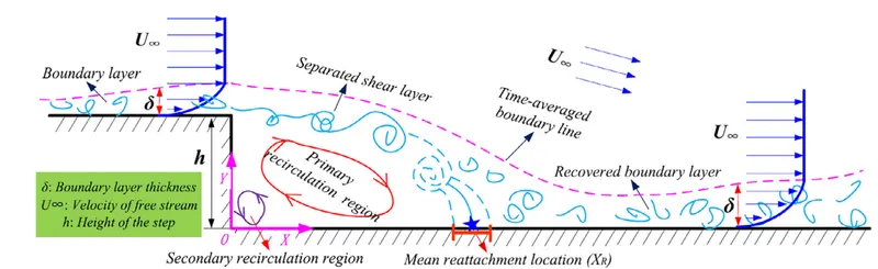
schematic for flow evaluation
Simulation setup
open converge studio application import the stl file to workspace and geometry setup is done
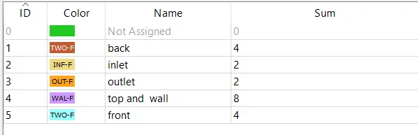
boundary
check for normal tongle if normal is facingoutside of the workpiece the transferm the normal becuse the flow is happein inside the workpiece
check for dignossis
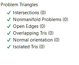
dignossis
case setup
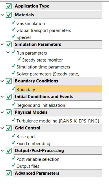
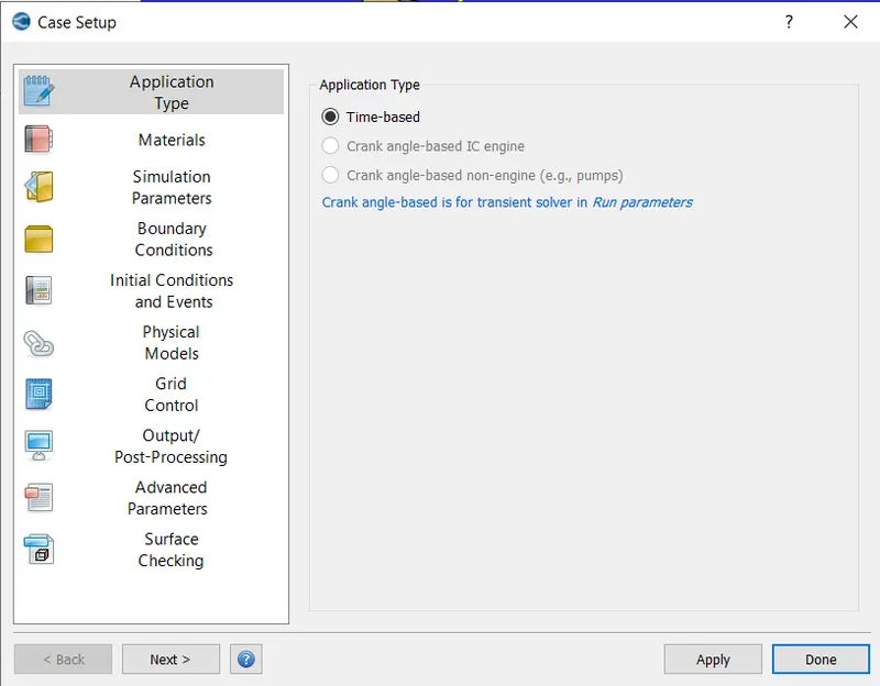
application type
MATRIAL PAREMETER VALIDATE them
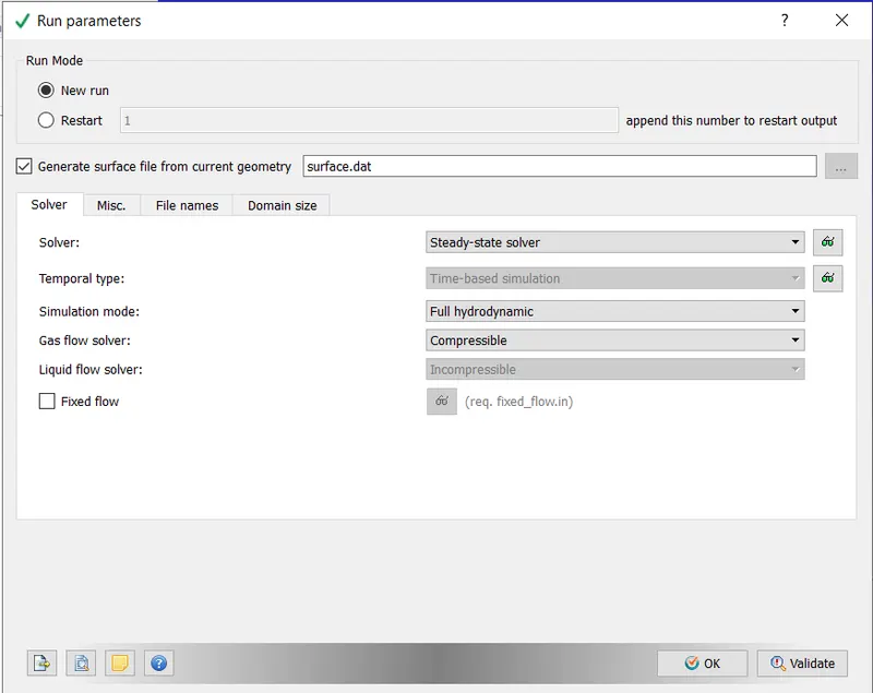
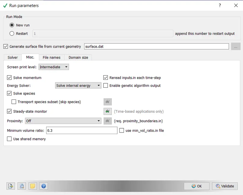
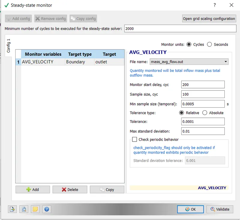
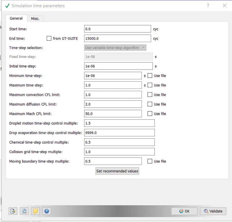
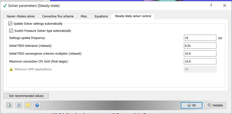
SIMLATION PARAMETER
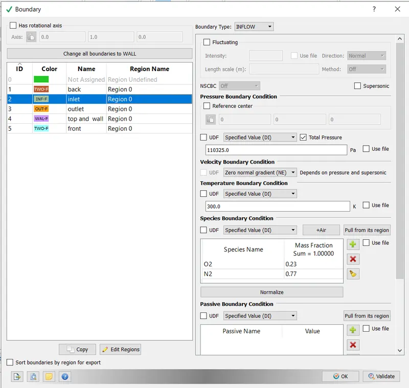
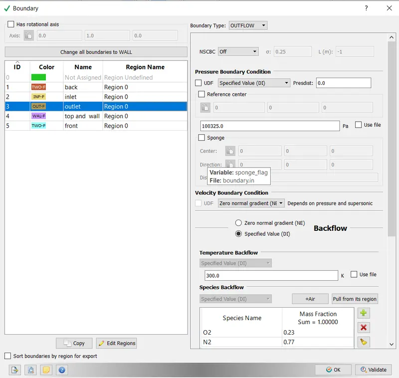
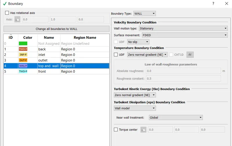
boudary setup
front and back selected two D
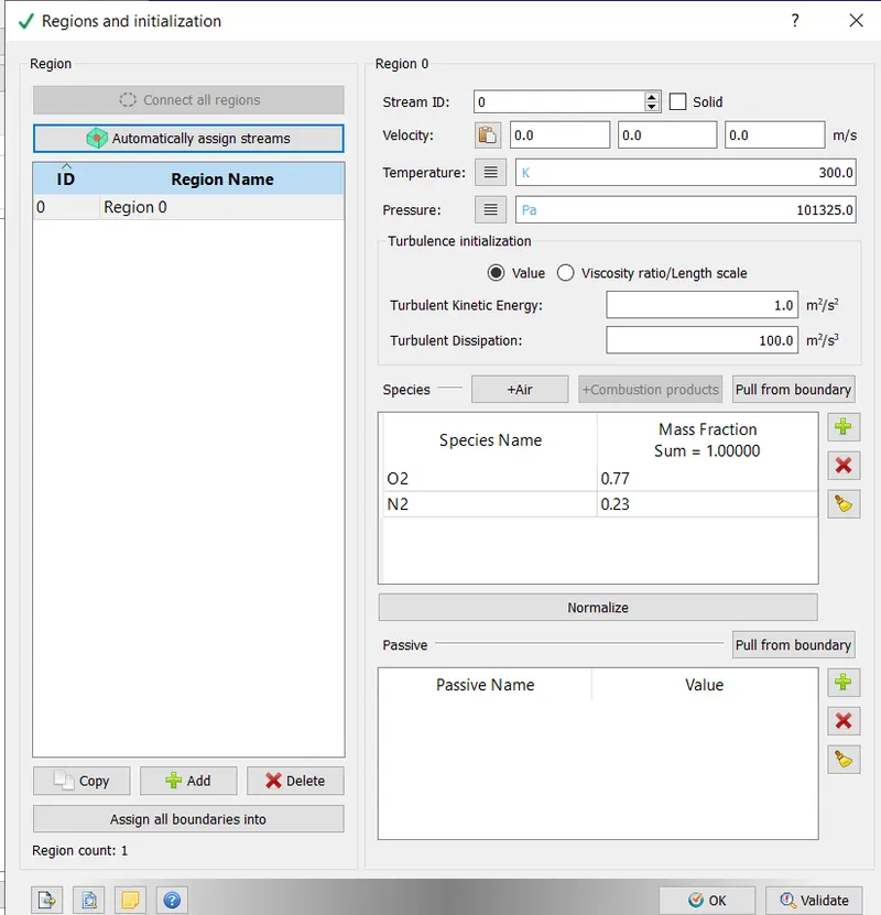
regions and intialization
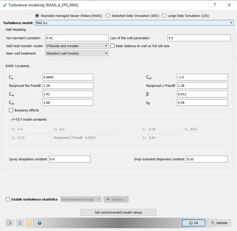
turbulence model
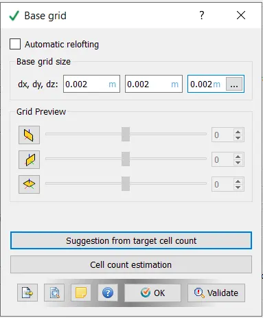
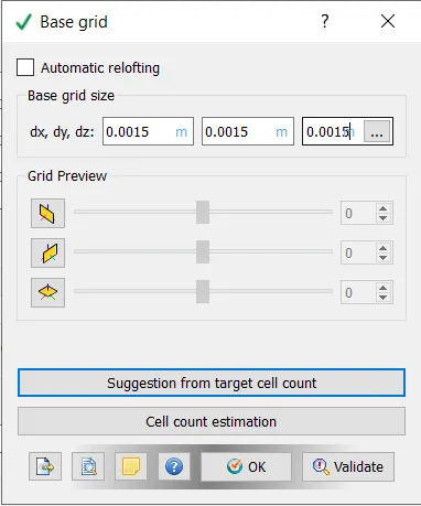
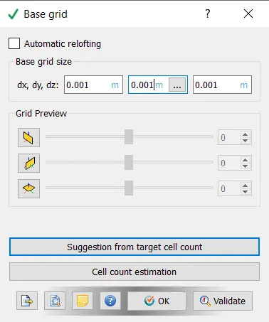
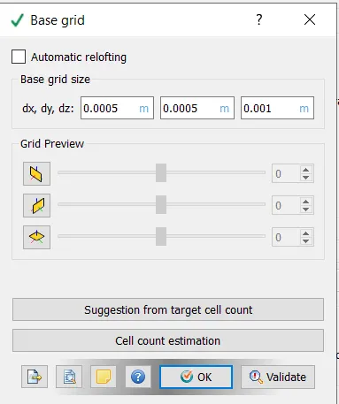
base gride for case 1, 2,3 and fine mesh
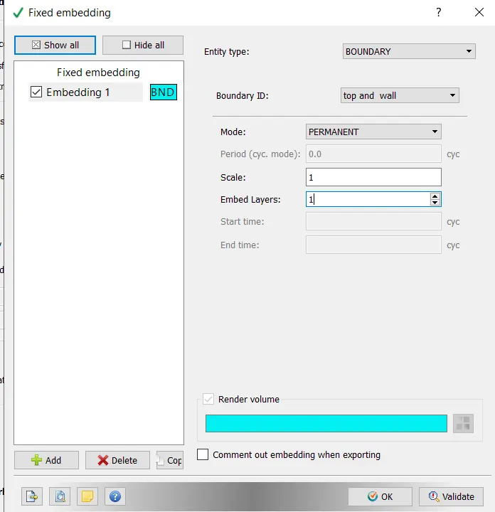
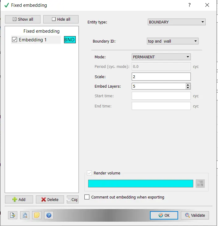
fix embedding for case set and fine setup
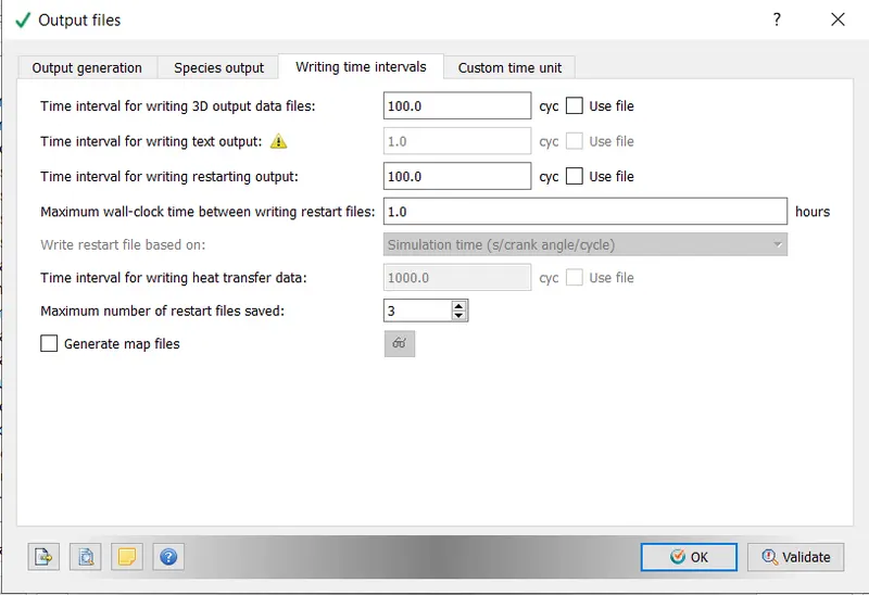
output files
after setup validate the set and export the files to a folder
the open cygwin and navigate to the perticular folder wher files are saved and run this command
mpiexec.exe -n 4 converge.exe restricted
wait till simulation complete the open converge studio and move to post processing to convert the simlated post file to readble file for paraview
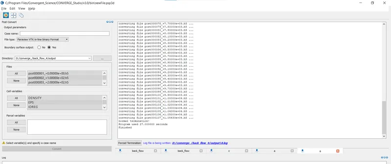
converting post process files
result
in converge studio move to line ploting to look for results
and post processs reslts were looked into paraview application
case 1
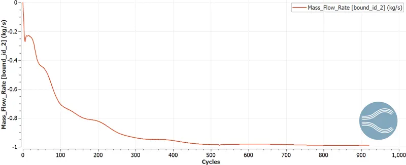
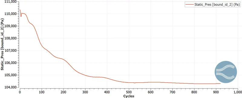
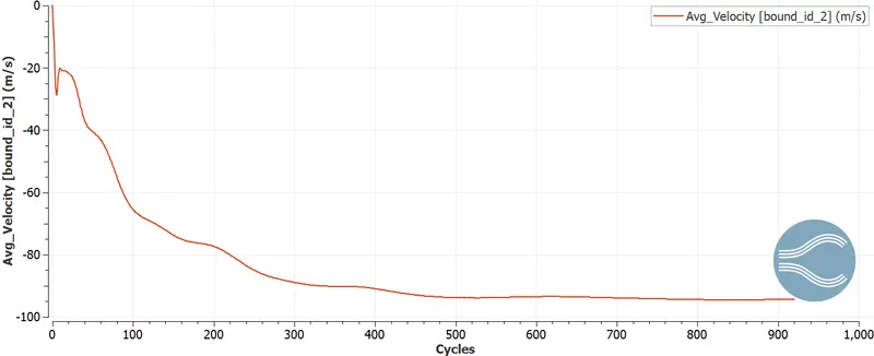
mass flow rate , pressure and velocity at inlet
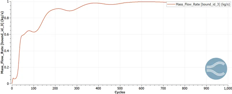
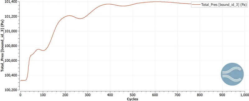
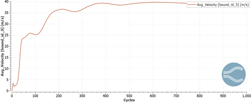
mass flow,pressure, and velocity at outlet
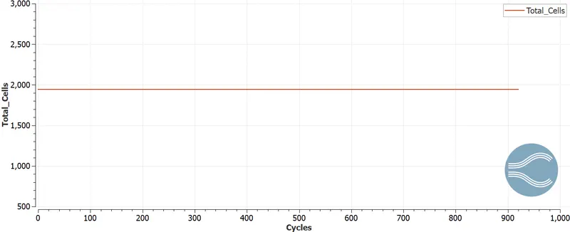
cell count
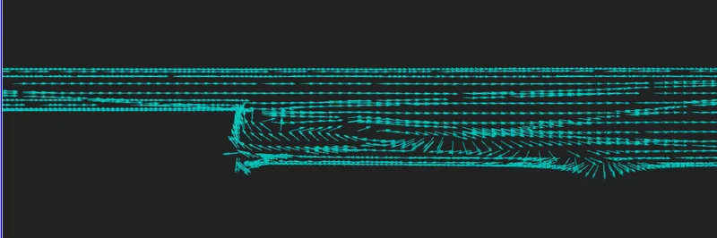
boundary seperation vector plot
case -2
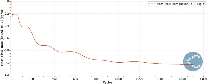
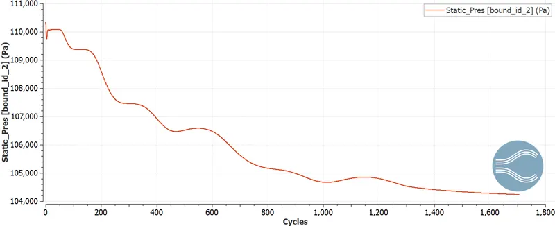
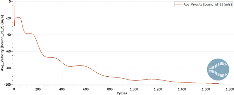
mass flow rate , pressure and velocity at inlet
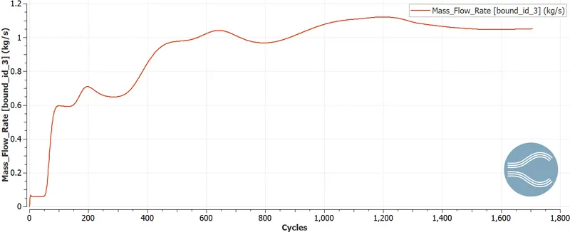
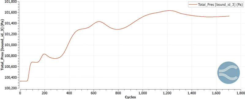
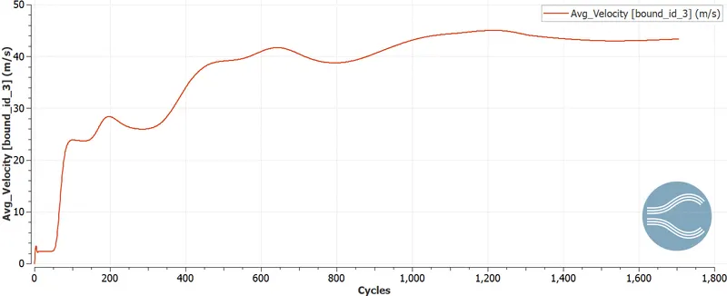
mass flow rate , pressure and velocity at outlet
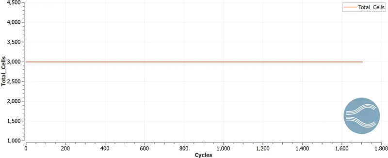
cell count
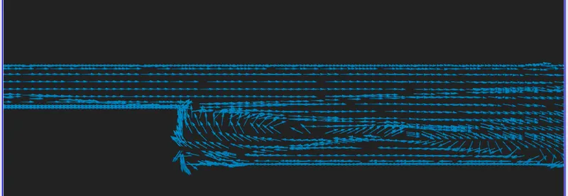
boundary seperation vector plot
case-3
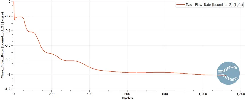
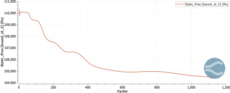
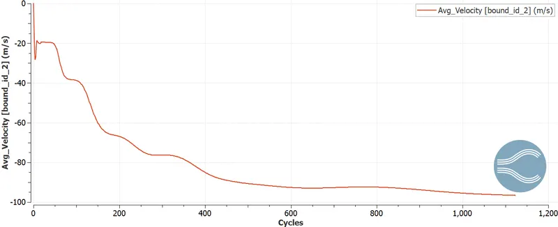
mass flow rate , pressure and velocity at inlet
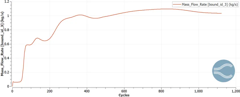
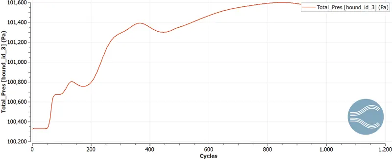
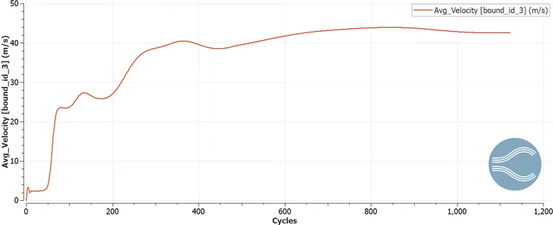
mass flow rate , pressure and velocity at inlet
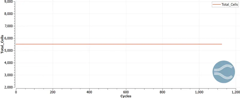
call count
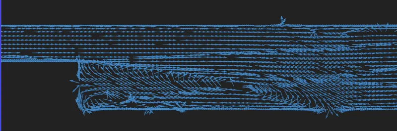
boundary seperation vector plot
case- fine mesh
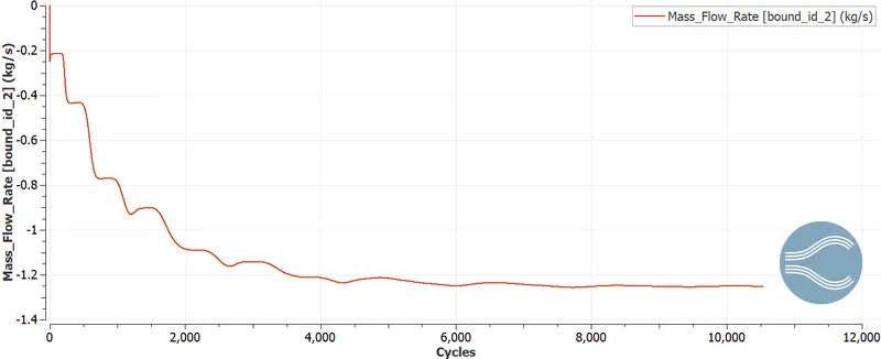
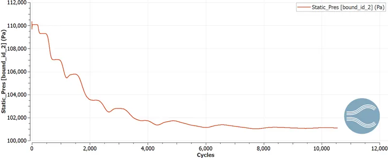
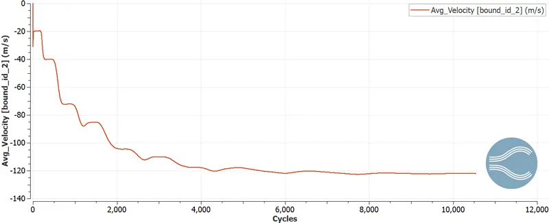
mass flow rate , pressure and velocity at inlet
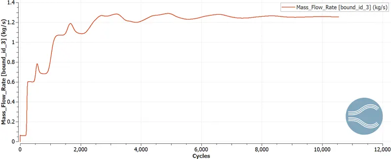
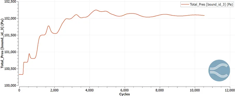
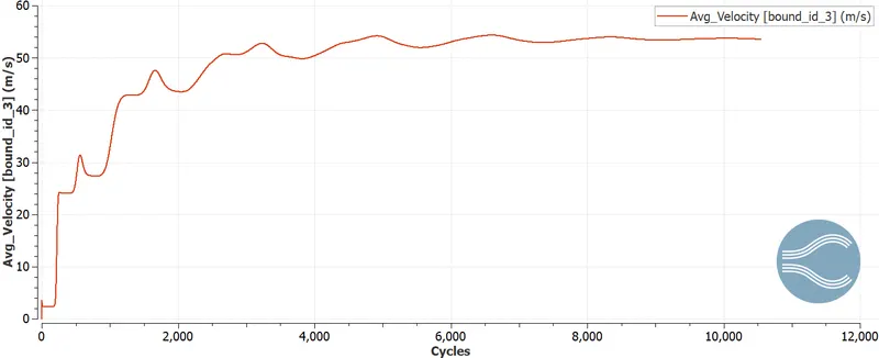
mass flow rate , pressure and velocity at oulet
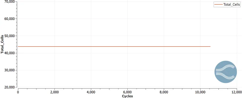
cell count
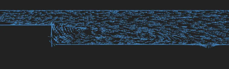
boundary seperation vector plot
conclusion
from boundary separation vector plot it can be seen that at the sudden expansion point there is flow seperation taking place this id due to sudden low pressure formation due to sudden expansion of area
at the end of the workpiece there is increse in pressure due o area exapnsion
due to low presure there is velocity vorte formation at the point
the animation of velocity, pressure contuer are uploaded in attachment zip file