Week 4 Challenge : CFD Meshing for BMW car
https://drive.google.com/file/d/1zJoNvILb6jr53b6XPVlTn4WSn6gSbpUJ/view?usp=sharing
pre volumetric mesh files
https://drive.google.com/file/d/1i05mGv3dL07WMoV32UQ2tifWsks9Wz7V/view?usp=sharing
volume meshed file
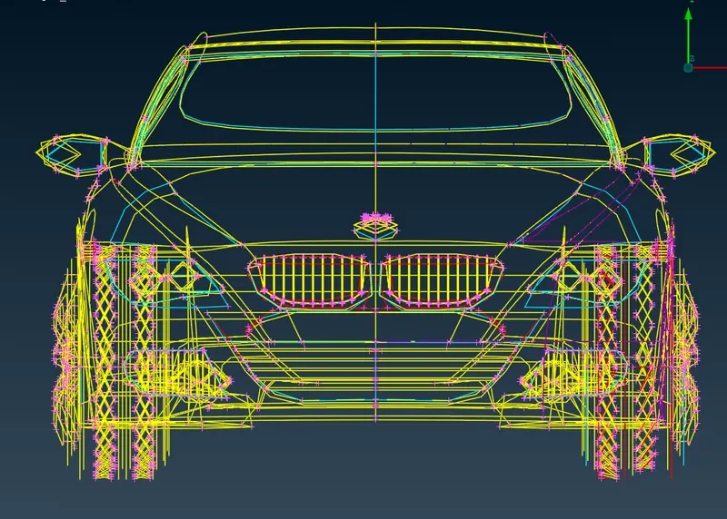
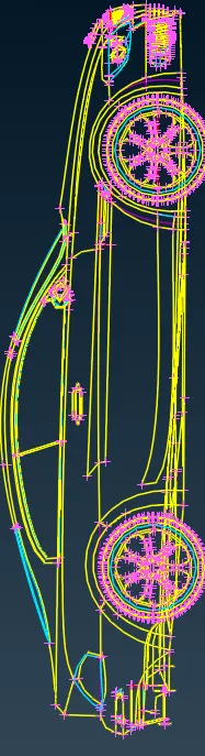
Fig 1 intial file imported with errors
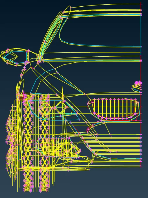
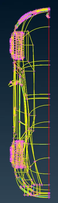
Fig 2 showing the half part used
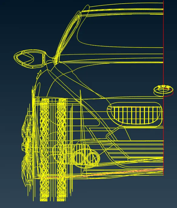
fig 3 error removed for half part
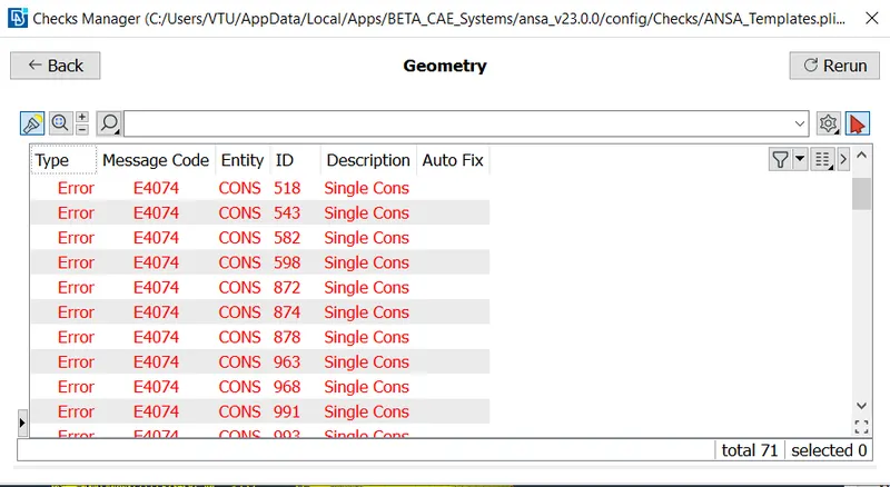
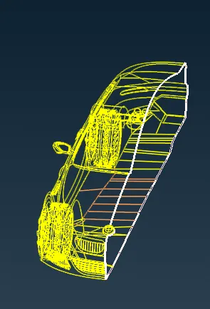
Fig 4 Geometry check for error free part
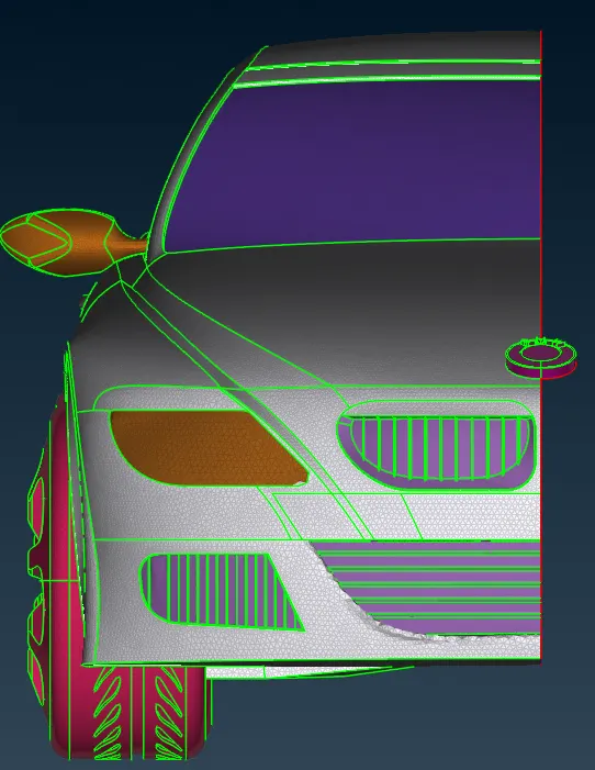
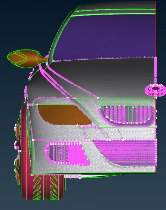
Fig 5 PID Assigned parts
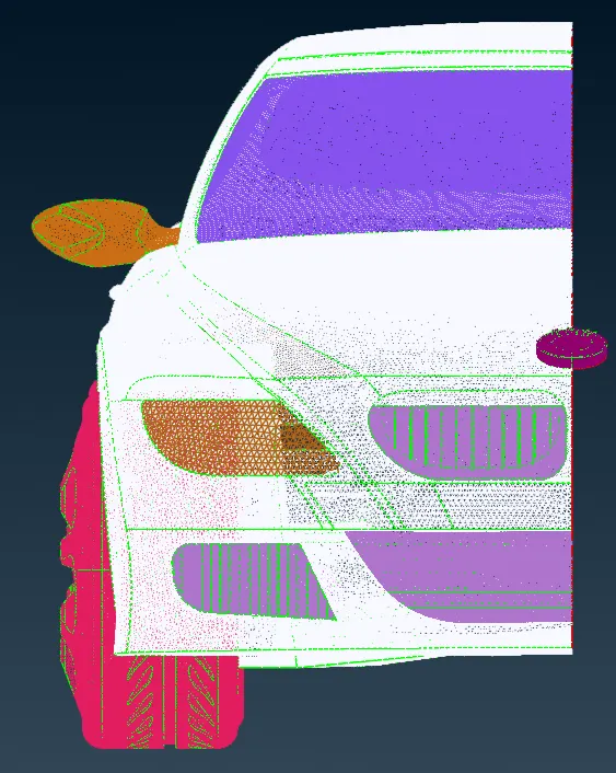
Fig 6 PID Assigned parts and meshed parts
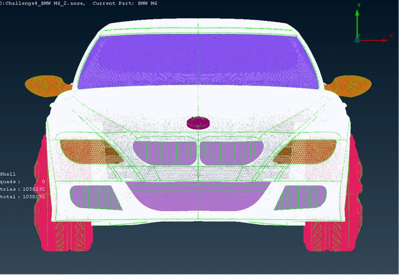
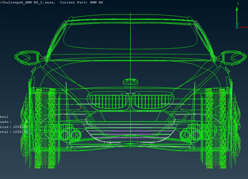
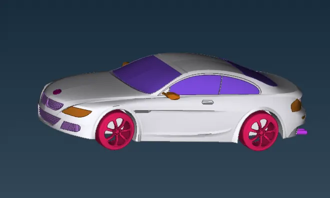
Fig 7 retracting Full parts by copying to other half part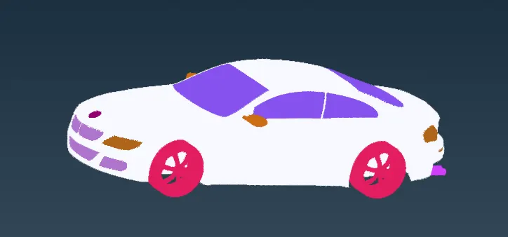
Fig 8 retracting Full parts by copying to other half part and meshed part
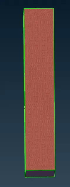
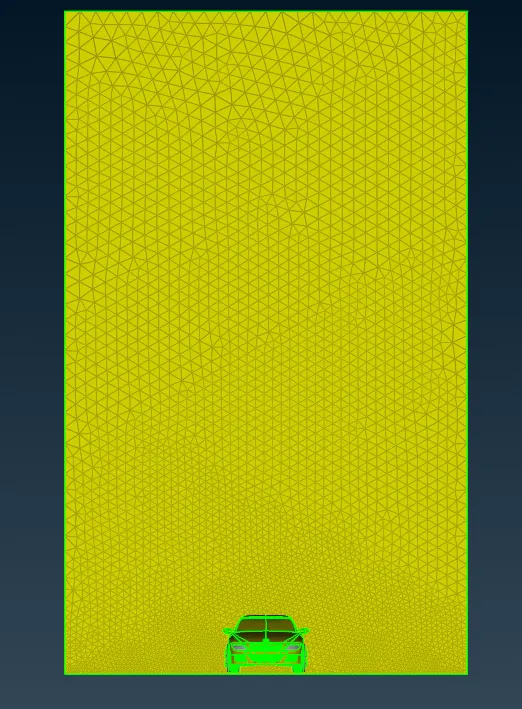
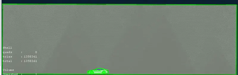
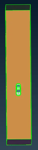
Fig 9 wing tunnel with car
 \
\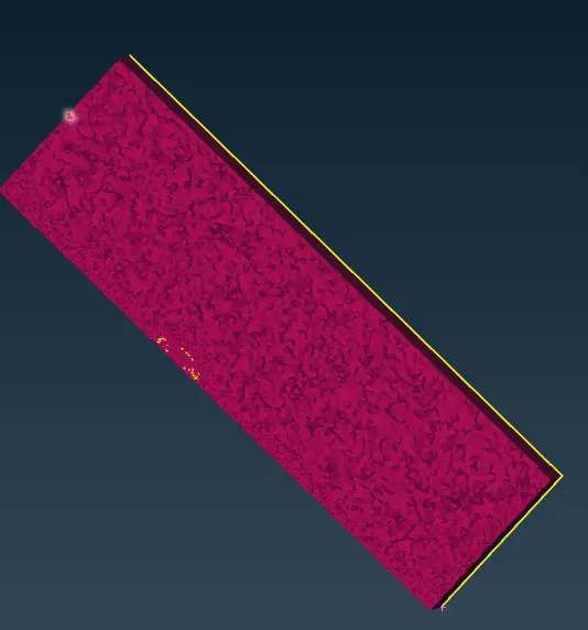
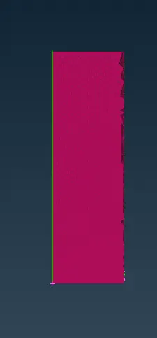
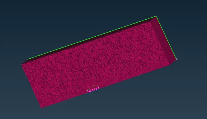
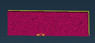
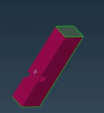
fig 10 volumetric mesh
Challenge 4
The steps involved in solving challenge 2 as follows: -
Check for geometry error
- Firstly, the file is imported to ANSA workspace.
- The car part id symmetric from front side so we can copy one half information to other half so that the car part half side is deleted.
- Workpiece is checked for geometry. Except for sharp edges and unmeshed marcos.
- There will be many errors of showing many single coned surfaces (edge with only one surface)
- Identify those single cons using control+shift key pressing before that from face draw section select marcos, perims and single.
- Identified single con can be converted to double cons using new command from face section and selecting b/w existing surf, fitted and coons by looking at preview and selecting appropriate fill void section to convert the single cons to double.
- Fill hole command can also be used from cons section to fill the continuous holes in one go
- Once the all the single cons were filled again check for geometry. Except the end of the half part there single cons present because the other half is not connected
- Convert all the volume into single volume to do volumetric mesh
- Removed single con is shown in Challenge4_BMW M6_error_free.ansa file.
Assigning PID
- Once the all-geometry error was removed then it’s time to assign PID (property id)
- Click on property double time then there is a section opened in that there is a shell property named PID is there
- Now add new PIDs for Body, Grills, Lights, Windows, Rearview optical mirror, tires and rims, Logo and silencer.
- Once PIDs created its time to assigning PIDs to the parts of workpiece by applying PIDs for particular part.
Meshing 3mm
3mm mesh is done for Body and Silencer
- define length of mesh using length command from mesh>parimeters section.
- Once double click on length there will be a pop up showing up with two options first select perimeters and select whole workpiece using left click on mouse and selecting whole workpiece then middle click enter length as 5 same done for marcos.
- Check for minimum length
- Once selected perimeter and marcos length now from quality criteria define minimum and maximum length as 1 and 4 respectively and asymmetry 0.5.
- The click on mesh parameter and enter target length as 3 mm and element type as Tria.
- Once done with all of above steps no moves to mesh generation section select spot mesh command and mesh by using PID region from feature selection section.
- Select each PIDs and click on spot mesh and middle click to mesh
Meshing 4mm
4mm mesh is done for Lights
- define length of mesh using length command from mesh>parimeters section.
- Once double click on length there will be a pop up showing up with two options first select perimeters and select whole workpiece using left click on mouse and selecting whole workpiece then middle click enter length as 4 same done for marcos.
- Once selected perimeter and marcos length now from quality criteria define minimum and maximum length as 3 and 5 respectively and asymmetry 0.5.
- The click on mesh parameter and enter target length as 2 mm and element type as Tria.
- Once done with all of above steps no moves to mesh generation section select spot mesh command and mesh by using PID region from feature selection section.
- Select each PIDs and click on spot mesh and middle click to mesh
Meshing 2mm
2mm mesh is done for Windows, Rearview Optical mirror and rims and tyres.
- define length of mesh using length command from mesh>parimeters section.
- Once double click on length there will be a pop up showing up with two options first select perimeters and select whole workpiece using left click on mouse and selecting whole workpiece then middle click enter length as 2 same done for marcos.
- Once selected perimeter and marcos length now from quality criteria define minimum and maximum length as 1 and 2 respectively and asymmetry 0.5.
- The click on mesh parameter and enter target length as 2 mm and element type as Tria.
- Once done with all of above steps no moves to mesh generation section select spot mesh command and mesh by using PID region from feature selection section.
- Select each PIDs and click on spot mesh and middle click to mesh
Meshing 1mm
1mm mesh is done for Logo and Grills
- define length of mesh using length command from mesh>parimeters section.
- Once double click on length there will be a pop up showing up with two options first select perimeters and select whole workpiece using left click on mouse and selecting whole workpiece then middle click enter length as 1 same done for marcos.
- Once selected perimeter and marcos length now from quality criteria define minimum and maximum length as 0.4 and 2 respectively and asymmetry 0.5.
- The click on mesh parameter and enter target length as 1 mm and element type as Tria.
- Once done with all of above steps no moves to mesh generation section select spot mesh command and mesh by using PID region from feature selection section.
- Select each PIDs and click on spot mesh and middle click to mesh
- Once the all the mesh is done look for off element and try to reconstruct the mesh if still off elements are present the try to remover them using move,split, reshape, and other metods to solve that particular issue
- Where ever there is missed mesh is mixed those parts were meshed but he meshes range from high value to low mesh length.
- Once the meshing is done then the half part is copied to form full car part using transfer command and coping the all entities except logo and selecting 3 part symmetry command to copy file symmetrically is used once the file id copied do topo over entire surface to join all newly copies surface and form double cons
- The meshed file is shown turbocharger meshed file.
Wind Tunnel making
To do cfd analysis Wind Tunnel is created
Steps involved to create Wind tunnel
- First the distance of car is measured from its extreme end once the distance measured then
- From front end appoint is created at distance of 4X of the car length same way done at back end but for distance 6X.
- From bottom of car a point is defined for bottom surface and side points are created using these points at distance of 1X from side end.
- For top side 3X distance is used to create point from all these points curves are created from curves surfaces created and PID assigned to them
Volumetric mesh
The volumetric mesh steps as follows
- First volumes are defined by auto detecting.
- The unwanted volumes were deleted then and volume was meshed for tetra cfd meshed and the wait till all part get meshed.
- The volume meshed file is uploaded in drive and link is paste in answer box.
Learning outcomes
cfd mesh is learned from scrach for BMW car
creating Tunnel and voumetric meshing is also lerned
Conclusion
volumetric mesh can be used to cfd anlysis of car in wind tunnel