Week 2 Challenge : Surface meshing on a Pressure valve
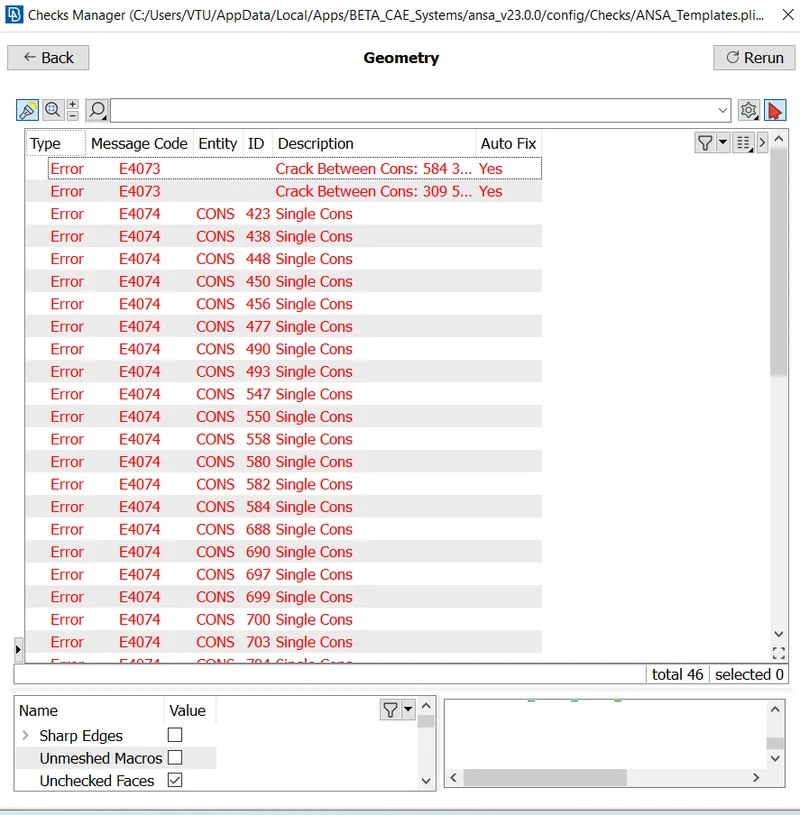
fig 1a error check geometry
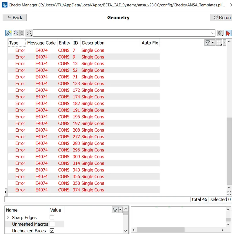
fig 1(b) error check geometry
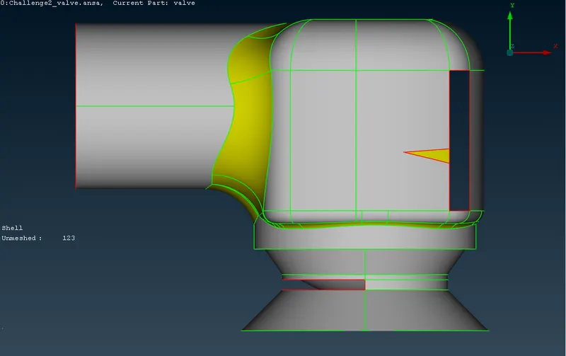
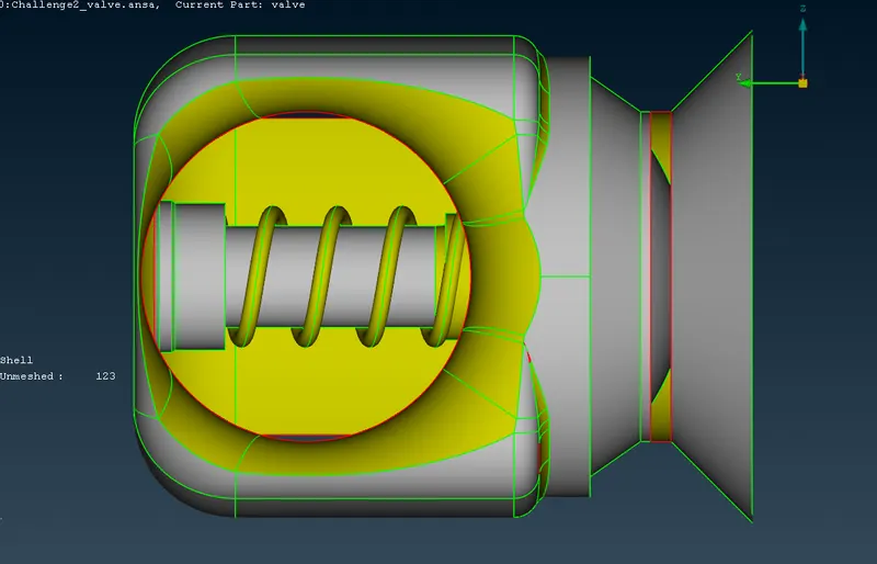

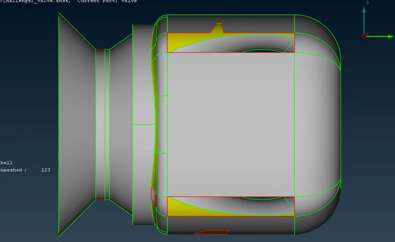
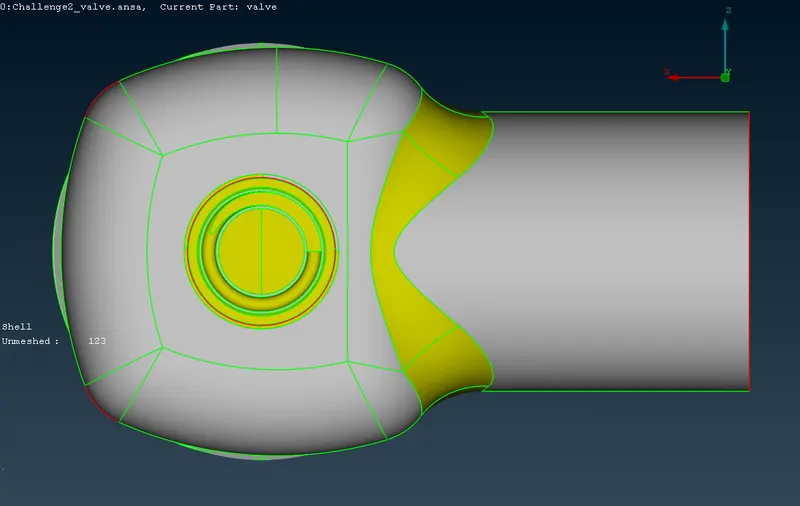
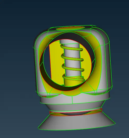
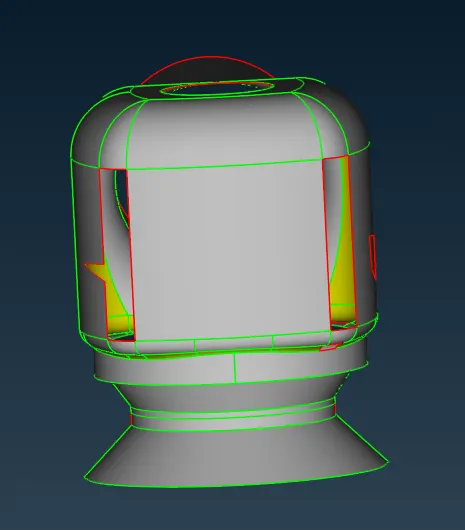
all figure showing single cons on workpiece in differnt views
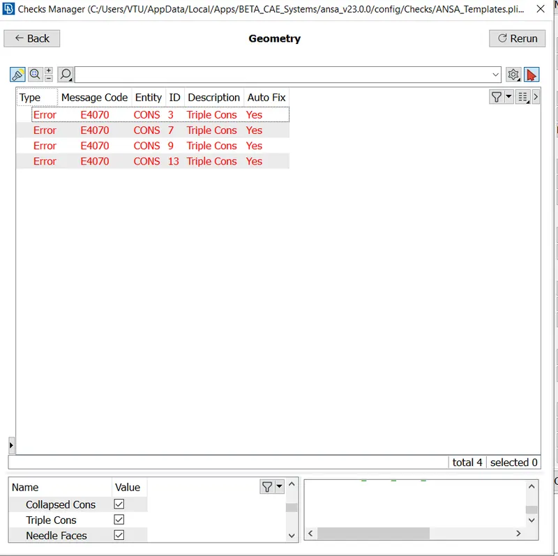
fig 2 showing all single cons removed
here show ing error of presence of triple con but these are not error because these triple cons are unavoideble and there is a clear contact of 3 suface so we can ignore these error
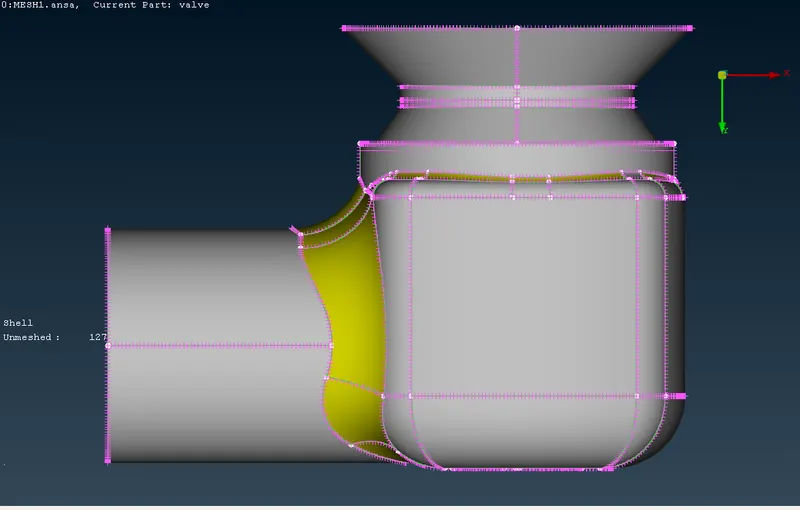
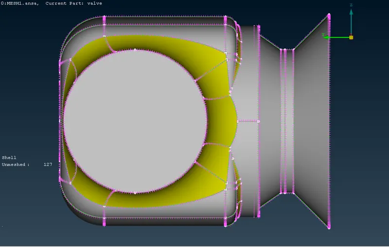
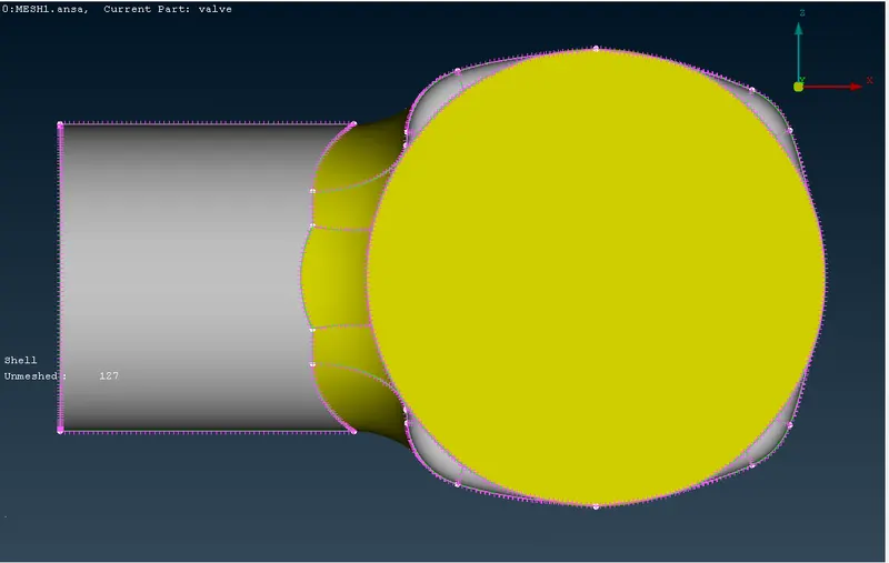
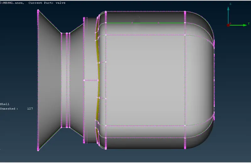
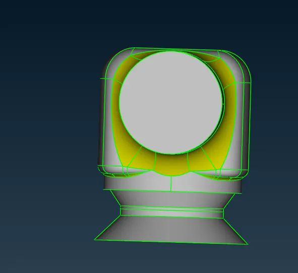
above figure showing removed single cons from workpiece
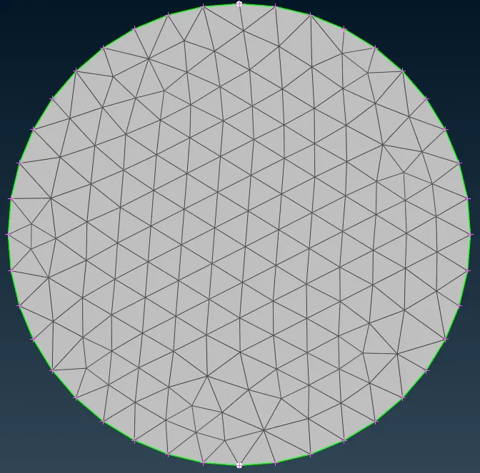
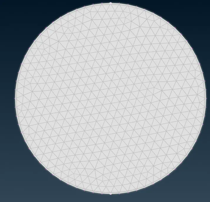
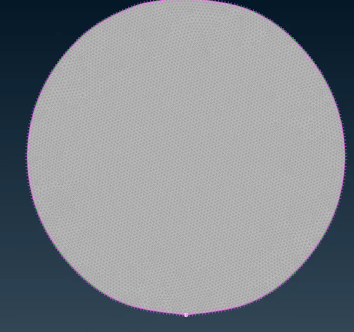
fig 3 inlet with 5mm, 3mm and 1mm mesh
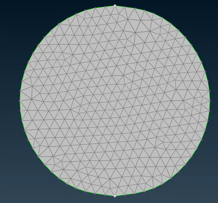
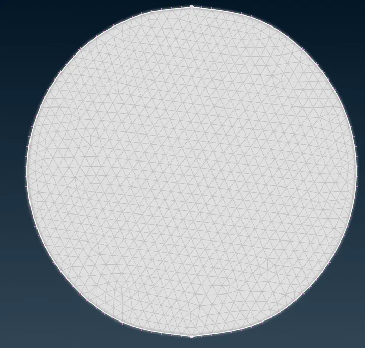
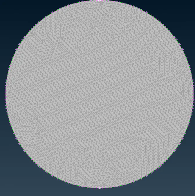
fig 4 outlet with 5mm, 3mm and 1mm mesh
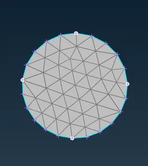
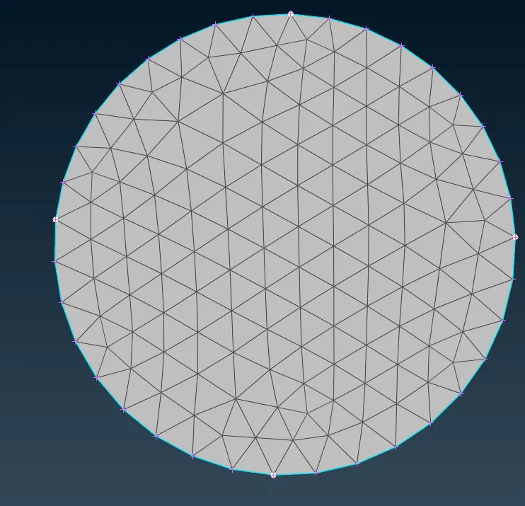
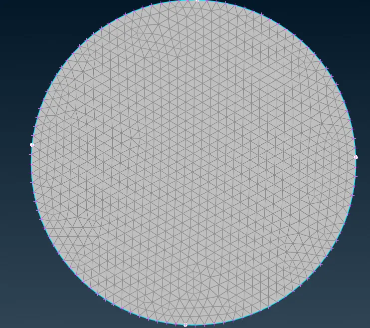
fig 5 base surfce with 5mm, 3mm and 1mm mesh
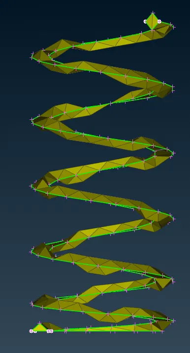
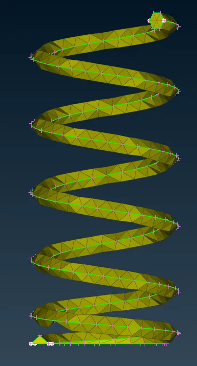
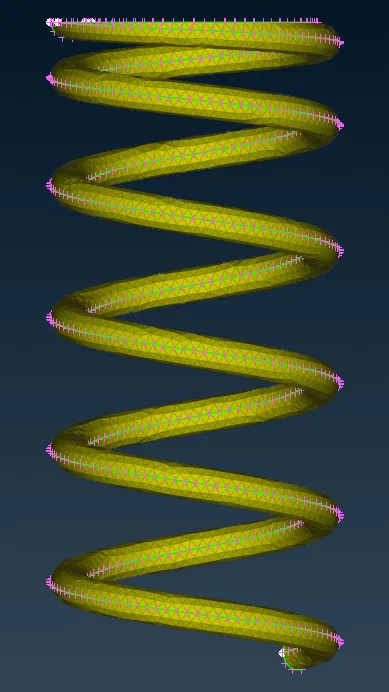
fig 6 springs with 5mm, 3mm and 1mm mesh
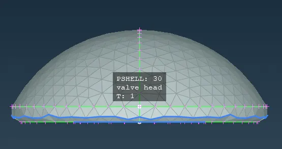
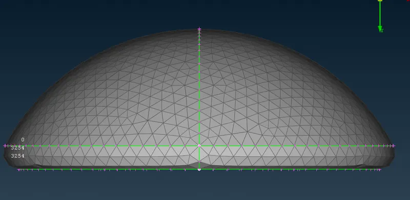
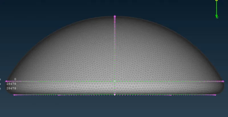
fig 7 valve head with 5mm, 3mm and 1mm mesh
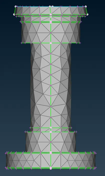
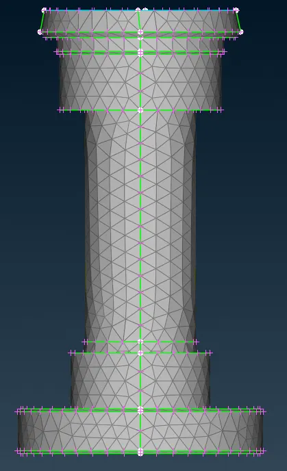
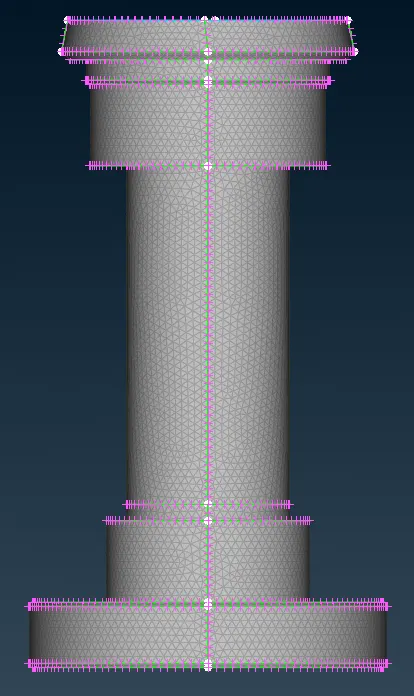
fig 8 column with 5mm, 3mm and 1mm mesh
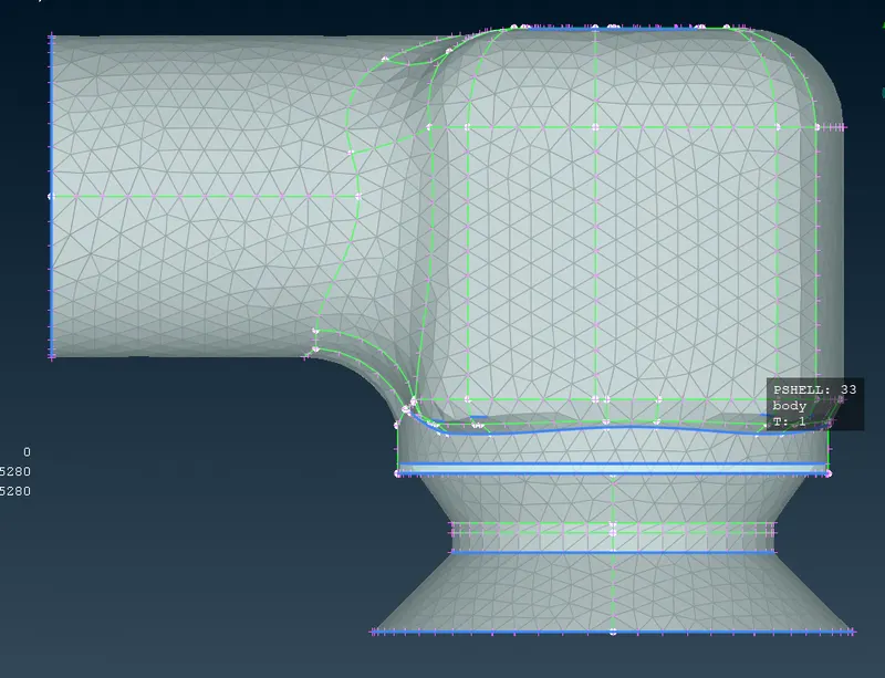
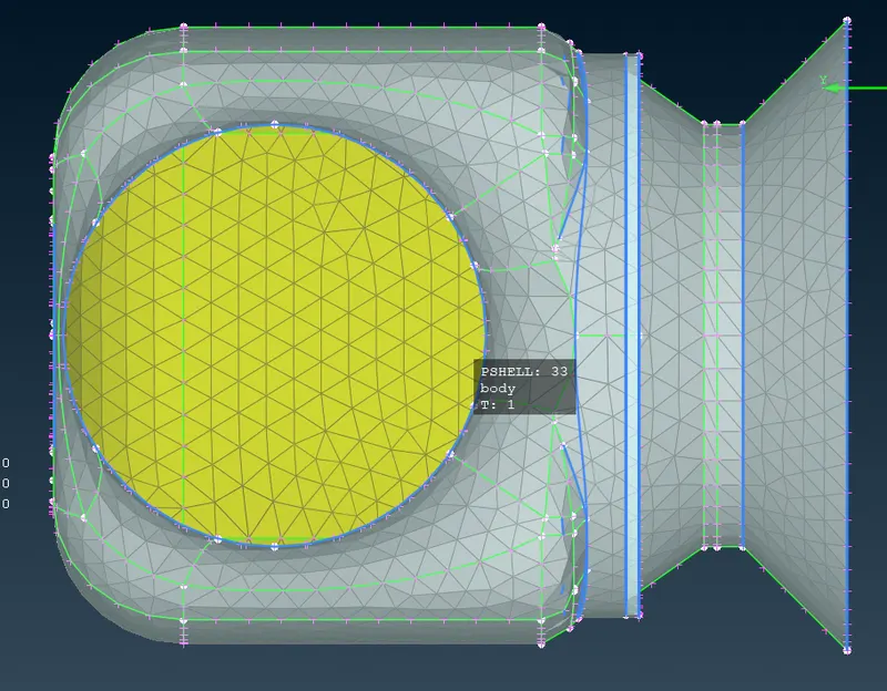
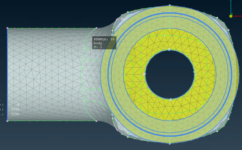
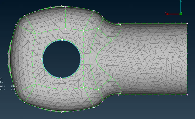
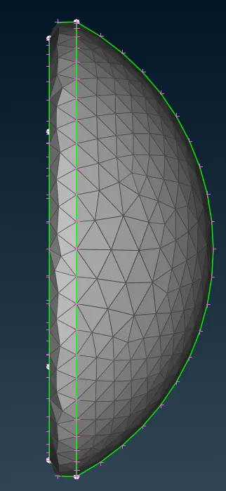
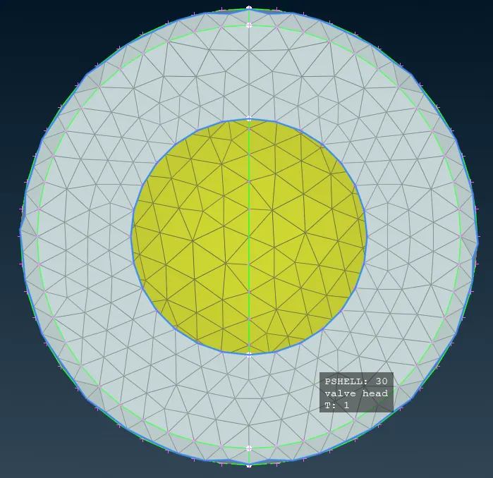
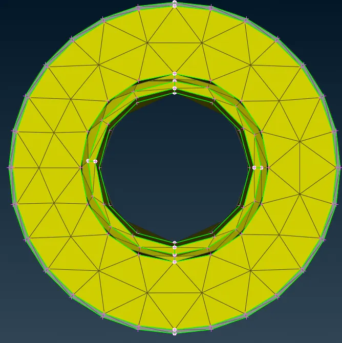
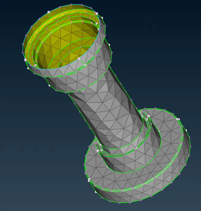
above all fig with 5mm mesh of body and other parts in defferent ange
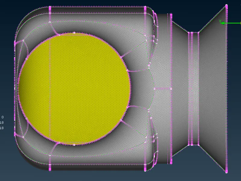
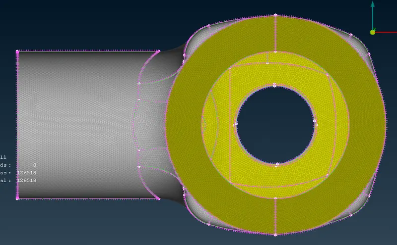
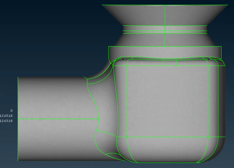
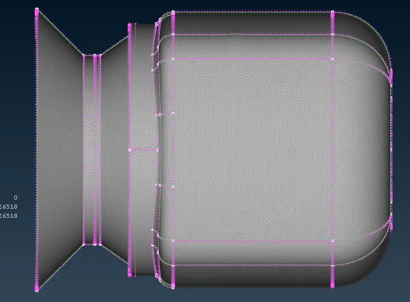
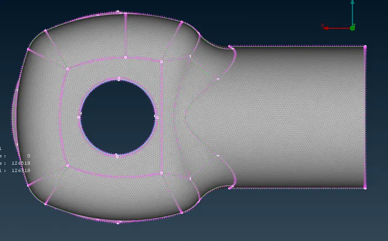
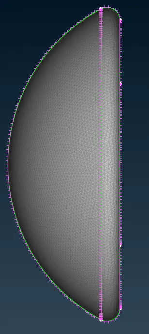
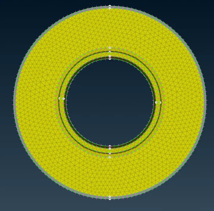
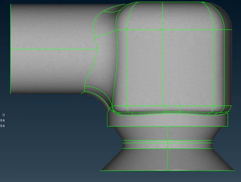
above all fig with 1mm mesh of body and other parts in defferent ange
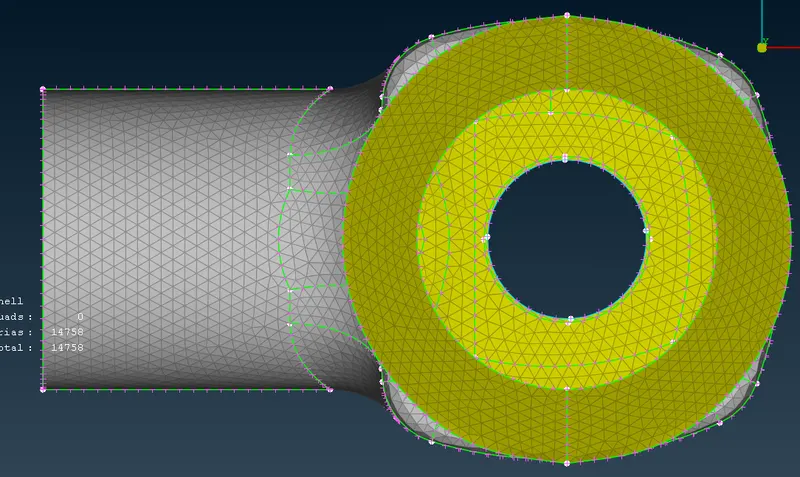
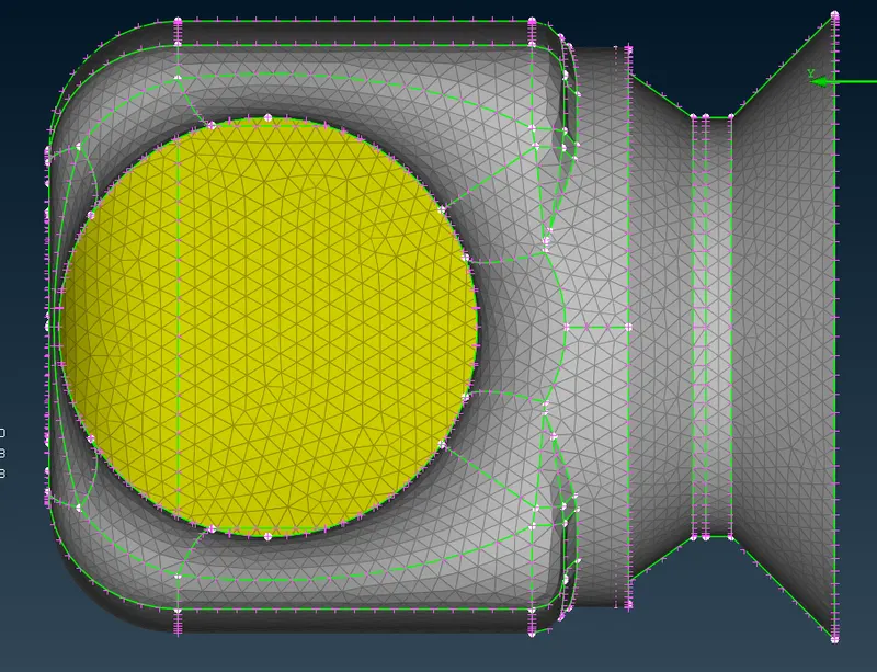
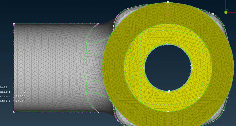
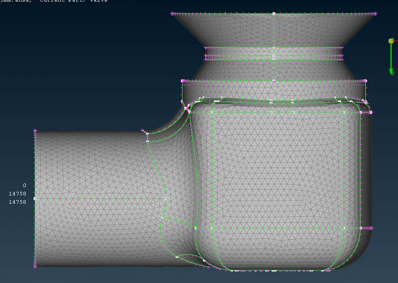
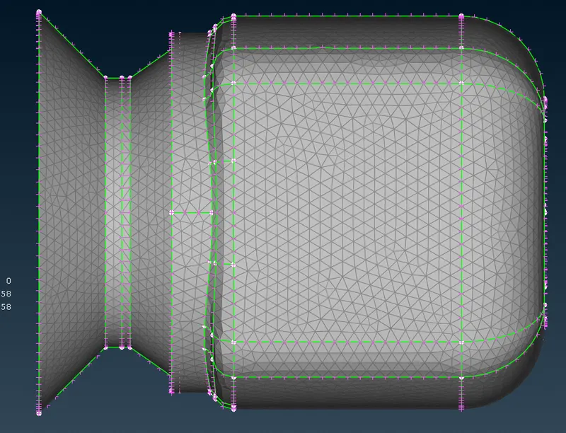
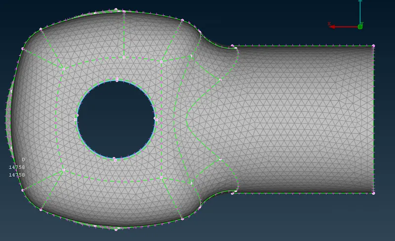
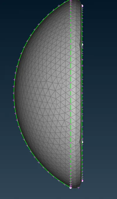
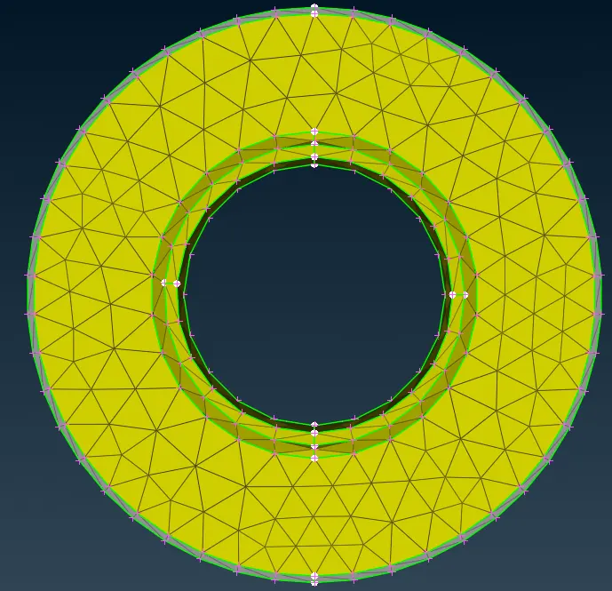
above all fig with 3mm mesh of body and other parts in defferent ange
figure information
fig 1 single con error
fig 2 triple con error
fig 3 inlet mesh details
fig 4 outlet meshn details
fig 5 base surface mesh details
fig 6 spring mesh details
fig 7 value head mesh details
fig 8 column mesh details
explanation:-
Challenge 2
The steps involved in solving challenge 2 as follows: -
Check for geometry error
- Firstly, the file is imported to ANSA workspace.
- Workpiece is checked for geometry. Except for sharp edges and unmeshed marcos.
- There will be many errors of showing many single coned surfaces (edge with only one surface)
- Identify those single cons using control+shift key pressing before that from face draw section select marcos, perims and single.
- Identified single con can be converted to double cons using new command from face section and selecting b/w existing surf, fitted and coons by looking at preview and selecting appropriate fill void section to convert the single cons to double.
- Fill hole command can also be used from cons section to fill the continuous holes in one go
- Once the all the single cons were filled again check for geometry.
- Now there show the triple cons error ignore that because where there surface are connected without that the attachment of workpiece is not possible.
- Removed single con is shown in solution1.ansa file
Assigning PID
- Once the all geometry error were removed then its time to assign PID(property id)
- Click on property double time then there is a section opened in that there is a shell_property named PID is there
- Now add new PIDs for inlet, outlet, body, Base surface, spring, valve head and column.
- Once PIDs created its time to assigning PIDs to the parts of workpiece by applying PIDs for particular part.
- Assigned PIDs is shown in mesh1.ansa file.
Meshing 5mm
- define length of mesh using length command from mesh>parimeters section.
- Once double click on length there will be a pop up showing up with two option first select perimeters and select whole workpiece using left click on mouse and selecting whole workpiece then middle click enter length as 5 same done for marcos.
- Once selected perimeter and marcos length now from quality criteria define minimum and maximum length as 3 and 7 respectively
- The click on mesh parameter and enter target length as 5 mm and element type as Tria.
- Once done with all of above steps no moves to mesh generation section select spot mesh command and mesh by using PID region from feature selection section.
- Select each PIDs and click on spot mesh and middle click to mesh
- The result of mesh is shown in MESH_5mm.ansa file.
Meshing 3mm
- define length of mesh using length command from mesh>parimeters section.
- Once double click on length there will be a pop up showing up with two option first select perimeters and select whole workpiece using left click on mouse and selecting whole workpiece then middle click enter length as 3 same done for marcos.
- Once selected perimeter and marcos length now from quality criteria define minimum and maximum length as 1 and 4 respectively
- The click on mesh parameter and enter target length as 3 mm and element type as Tria.
- Once done with all of above steps no moves to mesh generation section select spot mesh command and mesh by using PID region from feature selection section.
- Select each PIDs and click on spot mesh and middle click to mesh
- The result of mesh is shown in MESH_3mm.ansa file.
Meshing 1mm
- define length of mesh using length command from mesh>parameters section.
- Once double click on length there will be a pop up showing up with two option first select perimeters and select whole workpiece using left click on mouse and selecting whole workpiece then middle click enter length as 1 same done for marcos.
- Once selected perimeter and marcos length now from quality criteria define minimum and maximum length as 0.5 and 2 respectively
- The click on mesh parameter and enter target length as 1 mm and element type as Tria.
- Once done with all of above steps no moves to mesh generation section select spot mesh command and mesh by using PID region from feature selection section.
- Select each PIDs and click on spot mesh and middle click to mesh
- The result of mesh is shown in MESH_1mm.ansa file.
conclusion
from spring and vlave head it can be seen that when the meshing length is large there is distrotion is shape of spring and the valve head as the mesh length is decreased the geometry and meshing beacomes clean and less distroted its beacuse the spring has dia of 3.46 mm but the mesh length its self is 5 so there is distrotion in shape to avoid this this mesh length is decreased as a result there is improvement in shape and les distrotion