Week 8 - Simulating Cyclone separator with Discrete Phase Modelling
Week 8
Aim: - perform analysis on cyclone separator and calculate the separation efficiency and pressure drop.
Objective: -
- To write a few words about any four empirical models used to calculate the cyclone separator efficiency.
- To perform an analysis on a given cyclone separator model by varying the particle diameter from 1 μm to 5 μm and calculate the separation efficiency in each case. Discuss the results. [Use both the velocity's as 3m/sec.]
- To perform an analysis on a given cyclone separator model by varying the particle velocity from 1 m/sec to 5 m/sec and calculate the separation efficiency and pressure drop in each case. Discuss the results. [Use particle diameter size as 5 μm for all cases & keep flow velocity same as particle velocity]
Introduction: -
Cyclone separators are devices that employ a centrifugal force generated by a spinning gas stream to separate particles from the carrier gas.
Their simple design, low capital cost and nearly maintenance-free operation make them ideal for use as pre-cleaners for more expensive final control devices such as bag houses or electrostatic precipitators.
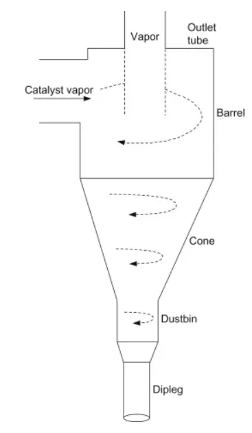
Fig 1 cyclone separator
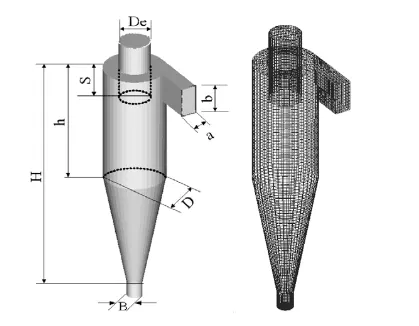

Fig 2 cyclone separator dimension
CYCLONE EFFICIENCY EMPIRICAL MODELS
- Iozia and Leith Model
The model assumes that a particle carried by the vortex endures 165 the influence of two forces: a centrifugal force, Z and a flow resistance, W.
The collection efficiency ηi of particle diameter dpi can be calculated from
`eta_i=1/(1+(d_(pc)/d_(p i))^beta`
- Li and Wang Mode
model includes particle bounce and turbulent diffusion at the cyclone wall. A two-dimensional analytical expression of particle distribution in the cyclone is obtained.
Li and Wang model was developed based 180 on the following assumptions
- The radial particle velocity and the radial concentration profile are not constant for uncollected particles within the cyclone.
- Boundary conditions with the consideration of turbu185 lent diffusion coefficient and particle bounce on the cyclone wall
`eta_i=((1-alpha)*K*W_w)/(D_r*r_w^n)`
- Koch and Licht Model
theory recognized the inherently turbulent nature of cyclones and the distribution of gas residence times within the cyclone.
Koch and Licht described particle motion in the entry and collection regions with the additional following assumptions:
- The tangential velocity of a particle is equal to the tangential velocity of the gas flow, i.e., there is no slip in the tangential direction between the particle and the gas.
- The tangential velocity is related to the radius of cyclone.
`eta_i=1``eta_i=1-(exp(-[(G*tau_i*Q)*(n+1)/D^3]^(0.5/(n+1))`
- Lapple Model
model was developed based on force balance without considering the flow resistance.
Lapple assumed that a particle entering the cyclone is evenly distributed across the inlet opening. The particle that travels from inlet half width to the wall in the cyclone is collected with 50% efficiency.
`eta_i=1/(1+(d_(pc)/d_(p i))^2`
Solving & Modelling approach
Geometry: -
Sapceclaim application is opened then cyclone separator geometry is imported in to the space claim application ten fluid volume extracted using volume extraction command then the main file is suppressed to physics the close the application.
Mesh
Meshing application is opened then name the inlet outlet_1 And outlet_2 by face selection and the insert a method select body and select Cartesian method and enter element mesh size as 10 mm and generate the mesh and close the application.
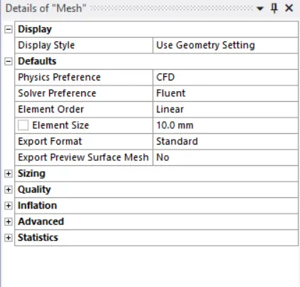
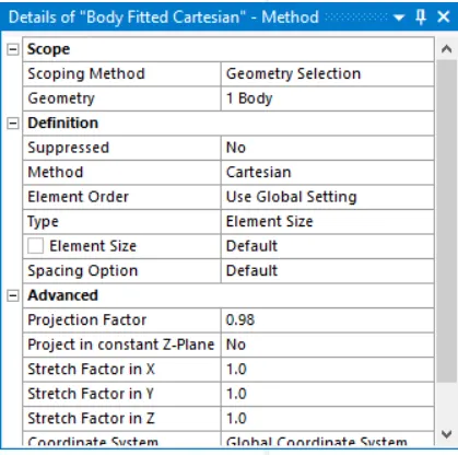
fig 3 mesh parameter
setup
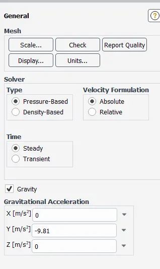
fig 4 solver setup
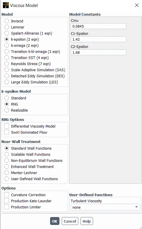
fig 5 viscous model setup
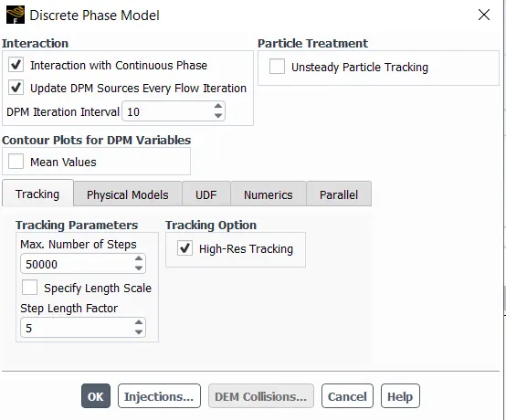
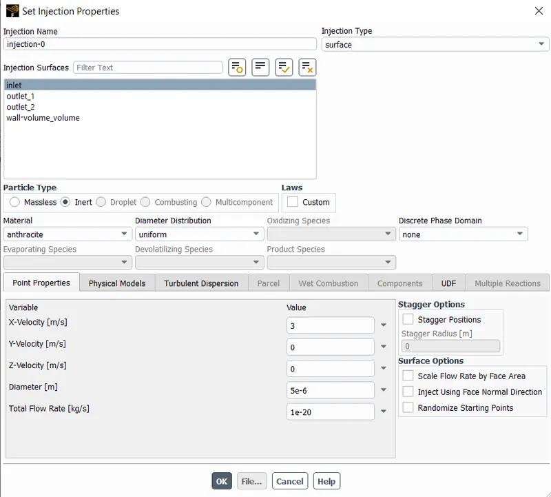
fig 6 DPM setp
boundary condtion
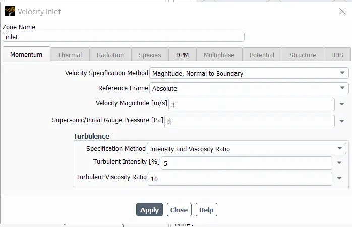
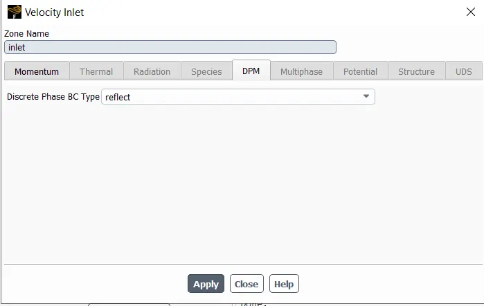
fig7 iblet BC
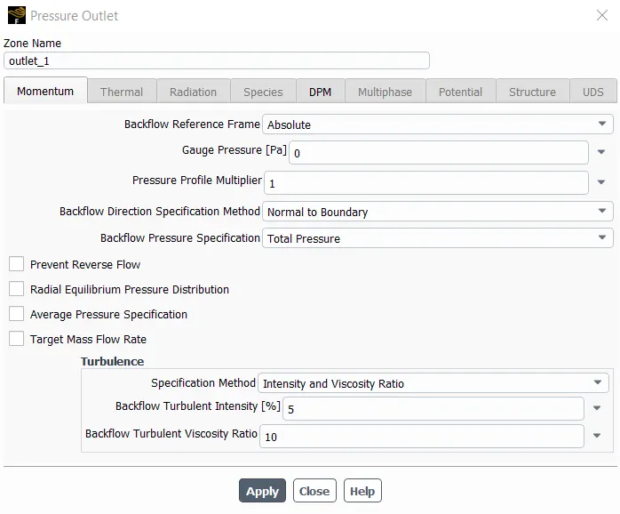
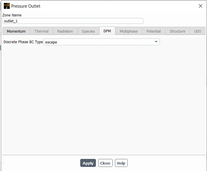
fig 8 outlet 1 BC
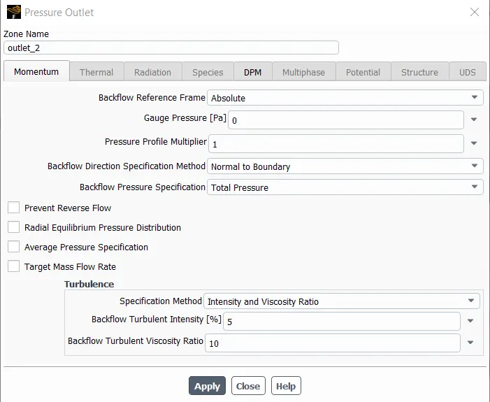
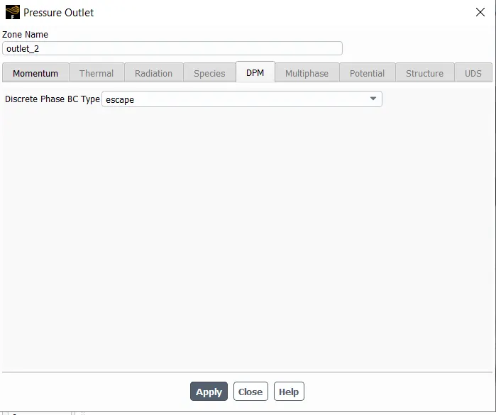
fig 9 outlet 2 BC
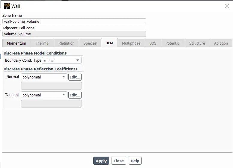
fig 10 wall BC
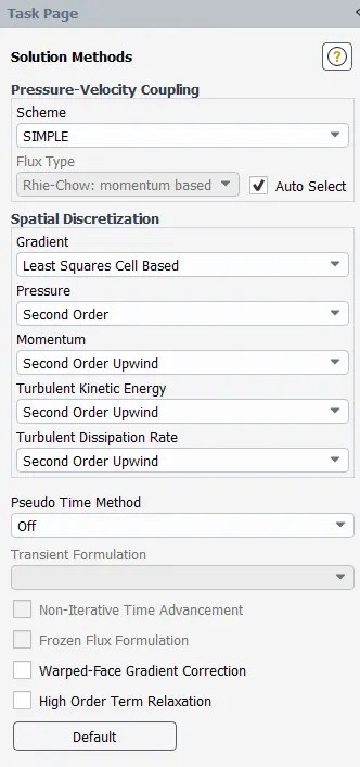
fig 11 method set up
intialzation
satdaer method slect inlet from option
calculate for 600 iteration
result
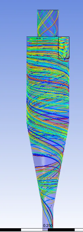
fig 12 partecle movement in 1micro meter particle at 3 m/s speed
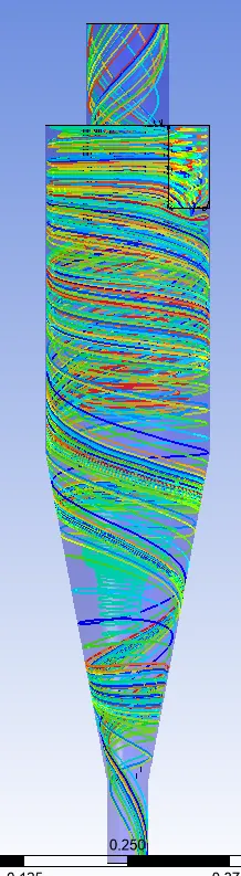
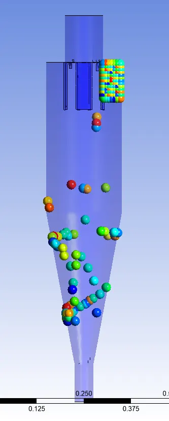
fig 13 partecle movement in 5micro meter particle at 3 m/s speed
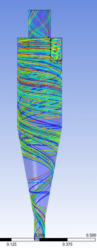
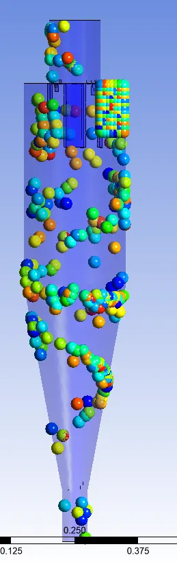
fig 14 partecle movement in 5micro meter particle at 1 m/s speed
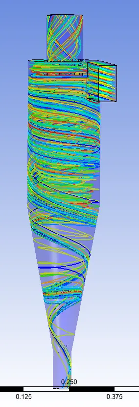
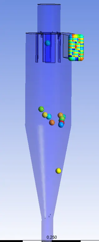
fig 15 partecle movement in 5micro meter particle at 5 m/s speed
Separation efficiency=
no of particles trapped*100/(no of particle injected/tracked-no of particles incomplete)
|
Particle size in micro meter |
Inlet velocity in m/s |
Tracked particles |
Escaped particles |
Trapped particles |
Separation efficiency |
|
1 |
3 |
91 |
25 |
66 |
72.52 |
|
5 |
3 |
91 |
31 |
60 |
65.93 |
|
5 |
1 |
91 |
23 |
68 |
74.72 |
|
5 |
5 |
91 |
40 |
51 |
56.04 |
conclusion
for same in let velocity when particle size changed there is sligth change in saperation effiecincy but when the particle size kept same velocity varied then ther is drop in effiecncy with increasing velocity.
animations for all simulation is uploaded in zip file