Week 12- Final project
DOOR TRIM PANEL
AIM
To develope a model of door trim panel following the design guidelines.
OBJECTIVE
- Creation of tooling direction and perfom draft analysis on the class A surface from the inputs door trim pane,Lower map pocket, Upper map pocket, Lower substrate, Door armrest.
- Creation of Class B and Class C surface and Solid body from the close surface.
- Ceating attaching feature according to master section such as flanges heat stakes.
- Creation of Engineering features like pushpins, heat stakes,ribs, doghouse, 4 way 2 way locatores whereever required with their design guidlines.
- Perfom draft analysis on the final part.
- Assemble all part togather with the push pines.
THEORY
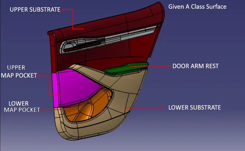
Door panels serve as a crucial intermediary within a car, bridging the gap between the vehicle's interior and the complex inner mechanisms of the door itself. They also act as a protective barrier between the vehicle's occupants and the various components housed within the door. These door panels are expected to adhere to a multitude of design criteria, encompassing safety, aesthetics, and functionality. Moreover, they are tasked with maintaining a consistent material theme that harmonizes with the dashboard and pillars while discreetly concealing the intricate electrical and mechanical elements required for functions such as locking mechanisms, window controls, and other features.
Over time, door panels have undergone a significant transformation. Initially, they comprised a straightforward two-part system, primarily focused on the latch and a basic winding mechanism. However, modern door panels have evolved into sophisticated enclosures. Contemporary vehicle doors typically feature full-width inner panels that house electronic window controls, central locking systems, and integrated speakers. These panels often consist of a foamed core that is covered with either textile materials or plastics, reflecting advancements in both design and technology.
Door trim panel consist of following components :
1.DOOR ARM REST
2.UPPER MAP POCKET and LOWER MAP POCKET
3.LOWER SUBSTRATE
4.UPPER SUBSTRATE
5.FLANGES
6.HEAT STAKES
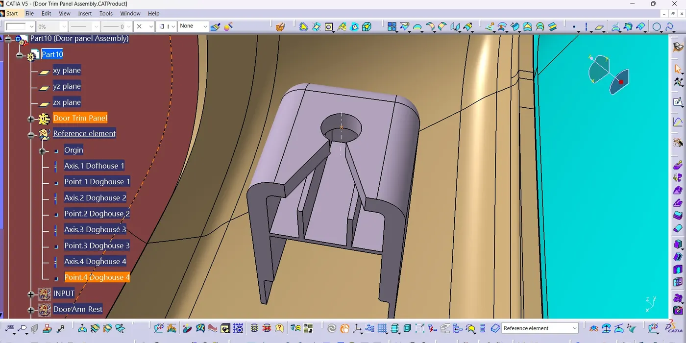
7.DOG HOUSE
1. Door Arm Rest
A door armrest is a functional component often found on the interior panel of a vehicle's door. It serves as a comfortable support for the driver's or passenger's arm while operating the vehicle. Typically padded or cushioned, it enhances comfort during long drives and provides a convenient resting place for the arm while driving or waiting in a parked vehicle. The design and materials of door armrests vary, but their primary purpose is to reduce driver fatigue and promote a more relaxed driving experience by offering a comfortable and ergonomic arm support within the car's cabin.
2. Map Pockets
Map pockets are storage compartments integrated into the interior of vehicles, offering convenient spaces to stow various items during travel. An upper map pocket is typically situated higher, often on the dashboard or sun visor, designed for easy access to smaller items like sunglasses, documents, or maps.
Conversely, a lower map pocket is usually located on the inner door panels at knee-level, ideal for storing larger items such as maps, magazines, or personal belongings. These pockets enhance organization, reducing distractions, and ensuring essential items are readily available, contributing to a safer and more comfortable driving experience for both drivers and passengers.
3. Lower Substrate
A door lower substrate refers to the structural component found in the lower portion of a vehicle's door assembly. It serves as the foundation or framework onto which various other elements, such as the door panel, trim, and power window mechanisms, are attached. This substrate is typically made of metal or sturdy composite materials, providing stability and durability to the door. It also contributes to the structural integrity of the vehicle, ensuring safety in case of accidents. The door lower substrate is a crucial part of the door assembly, playing a significant role in maintaining the overall functionality and safety of the vehicle's doors.
4. Upper Substrate
The door upper substrate is a critical component of a vehicle's door structure, typically positioned in the upper part of the door assembly. It forms the structural framework onto which various elements like the exterior door skin, window frame, and interior trim are attached. Often constructed from metal or strong composites, the door upper substrate provides rigidity and support to the door, aiding in impact resistance and crash safety. It also plays a role in noise and thermal insulation, contributing to passenger comfort. In essence, the door upper substrate is fundamental for the door's structural integrity, functionality, and overall safety within the vehicle.
5. Flanges
Flanges in a door trim panel refer to raised, often elongated edges or borders around the perimeter of the panel. These flanges serve several essential functions in automotive design. First, they provide structural support and rigidity to the trim panel, ensuring it maintains its shape and integrity. Second, they facilitate the attachment of the trim panel to the vehicle's door frame or substrate, typically through screws, clips, or other fasteners. Lastly, flanges help conceal the gaps or seams between the trim panel and the door, creating a visually seamless and finished appearance, enhancing both aesthetics and overall vehicle interior quality.
6. Heat stakes
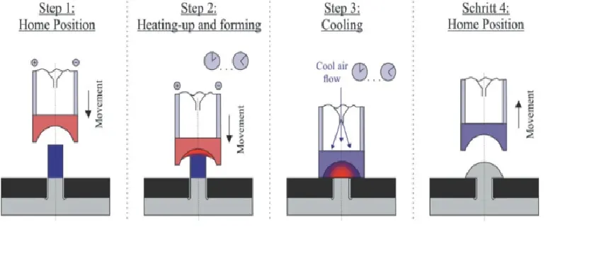 Heat stakes in a door trim panel are small, raised plastic points or posts used in manufacturing to secure various components of the panel together. They are heated and melted during assembly, allowing them to bond with other parts or layers of the panel, such as attaching fabric or padding to the main plastic structure. Heat stakes create a strong, permanent connection without the need for additional fasteners like screws or adhesives. This efficient and cost-effective method not only simplifies production but also contributes to the trim panel's overall integrity, ensuring it remains securely assembled within the vehicle's door, even under stress and vibration.
7. Dog House
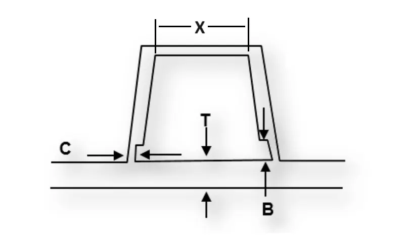
In plastic injection molding, a "doghouse" is a term used to describe a raised or thickened area on a plastic part. This raised area is strategically designed into the part to provide additional material and strength in areas where engineering features like snaps, locators, fasteners, or other elements will be attached. It helps prevent deformation, breakage, or distortion of the plastic part during the molding process, ejection from the mold, and subsequent assembly.
Design Criterias:
- C thickness should be 40% or less of the main wall thickness T
- Minimum width(X) of the dog house is 12 mm.
- Height of doghouse should be greater than or equal to 6 mm.
- Height of B should be 3-6 mm
- Minimum draft for the dog house is 1.5 degree to main tooling axis and 0.5 to side core tooling axis.
- Minimum Inner fillet radius should be 0.25 mm * Wall thickness T
- Wall thickness of dog house should be greater than or equal to 0.75 mm * Wall thickness.
Tooling Axes
Main Tooling Axis
The main tooling axis, often referred to as the "A-axis" or "primary axis," serves as the central point around which the core and cavity halves of the mold rotate or move during the molding process. This primary axis is typically aligned with the centerline of the mold and corresponds to the primary movement of the molding machine. The main tooling axis plays a fundamental role in the basic operation of the injection molding machine by allowing the mold to open and close. This opening and closing action creates the necessary space for injecting molten plastic into the cavity and subsequently ejecting the finished part after cooling and solidification.
Side Core Tooling Axis
The side core tooling axis, often referred to as the "B-axis" or "secondary axis," is an additional axis employed in more complex molds, especially when the part design includes features that cannot be formed through the simple opening and closing of the mold. The side core tooling axis facilitates the movement of side cores or slides within the mold. These side cores are movable components that are crucial for creating undercuts or complex features on the part by moving perpendicular to the main tooling axis. Side cores are typically utilized when the part design includes features like holes, threads, or undercuts that cannot be directly achieved through the mold's main movement. By coordinating the B-axis movement with the A-axis movement, intricate part geometries can be produced, expanding the capabilities of plastic injection molding for manufacturing complex plastic components.
Class A Surfaces
Class A surfaces are the highest quality surfaces in plastic design. They are typically used for visible, exterior, and highly aesthetic parts of a product, such as car body panels, consumer electronics casings, or high-end product enclosures. Characteristics of Class A surfaces include exceptional smoothness and gloss, no visible imperfections, precise and continuous curves and contours, minimal parting lines, and tight tolerances. Achieving Class A surfaces often requires advanced design and manufacturing techniques, including advanced CAD modeling, precise mold tooling, and careful material selection.
Class B Surfaces
Class B surfaces are of lower quality compared to Class A but are still visually acceptable for many applications. They are used for parts where aesthetics are important but not as critical as in Class A surfaces. Examples include interior automotive components, consumer electronics interiors, and certain appliance casings. Characteristics of Class B surfaces include good surface finish with minimal imperfections, tolerances that are not as tight as Class A surfaces, and some visible parting lines and minor imperfections that may be acceptable.
Class C Surfaces
Class C surfaces are functional surfaces that do not have strict aesthetic requirements. They are used for parts where appearance is not a primary concern, often because they are hidden from view or serve a structural or functional purpose rather than an aesthetic one. Characteristics of Class C surfaces include being functional but may have rougher finishes and visible imperfections, tolerances that may be relatively loose compared to Class A and Class B surfaces, and typically, less emphasis on achieving perfect surface quality, as long as the part meets its functional requirements.
3-2-1 Principle
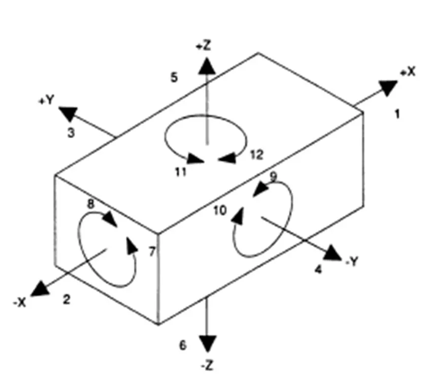
To locate a part to be machined and restrict its motion to accurately do the machining and constraint its motion 3-2-1 principle of location is used.There are 12 degree of motion for a 3D object in space, which are :
- Translational along the +X axis
- Translational along the -X axis
- Translational along the +Y axis
- Translational along the -Y axis
- Translational along the +Z axis
- Translational along the -Z axis
- Rotation along X-axis Clockwise
- Rotation along X-axis Anti-Clockwise
- Rotation along Y-axis Clockwise
- Rotation along Y-axis Anti-Clockwise
- Rotation along Z-axis Clockwise
- Rotation along Z-axis Anti-Clockwise
In this principle we use 3 points at the bottom of the cube (above), which restricts the translational motion along Z(Z+ and Z-), Rotational motion along Y and X(7, 8, 9, 10) This way three degrees of motions have been restricted.
Then 2 points from the Y direction of the cube to restricts the Translational motion along with Y(Y+ and Y-), Rotational motion along with Z. This way two degrees of motion are restricted.
Finally to restrict motion along the only remaining degree of freedom that is the Translational motion along the X(X+ and X-) a single point is used along the X+ direction of the cube to restrict all the motion.
PROCEDURE
Component 1 : Door Arm Rest
Step 1 : Divide and arrange the input components of Class A surface and check the surface quality,Then Create the tooling Axis
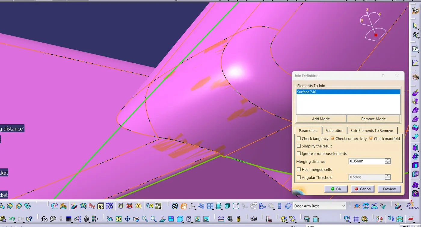
- Used join command to find the open boundries and cleared them.
- Insert a geometrical set for tooling axis for the first component whcih is the Door Arm Rest.
- Make a point on the surface and draw a line using point and direction along Z axis.
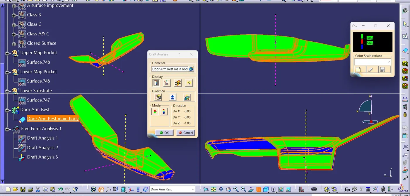
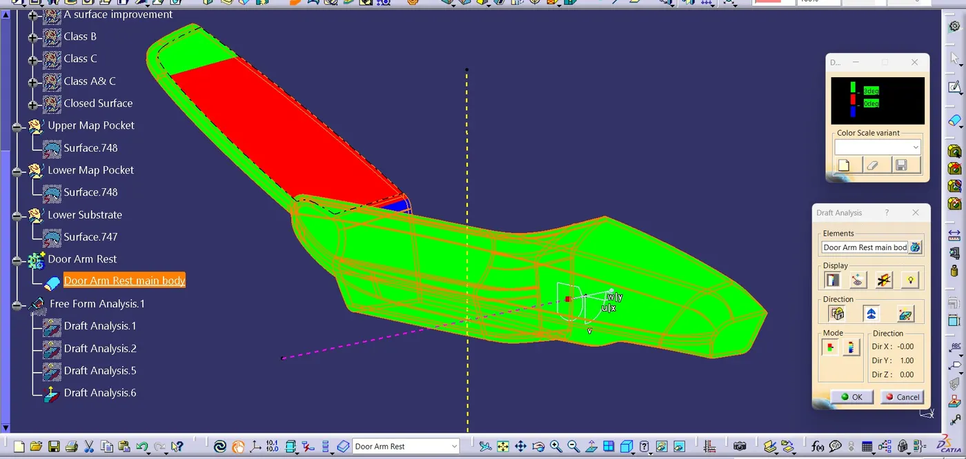
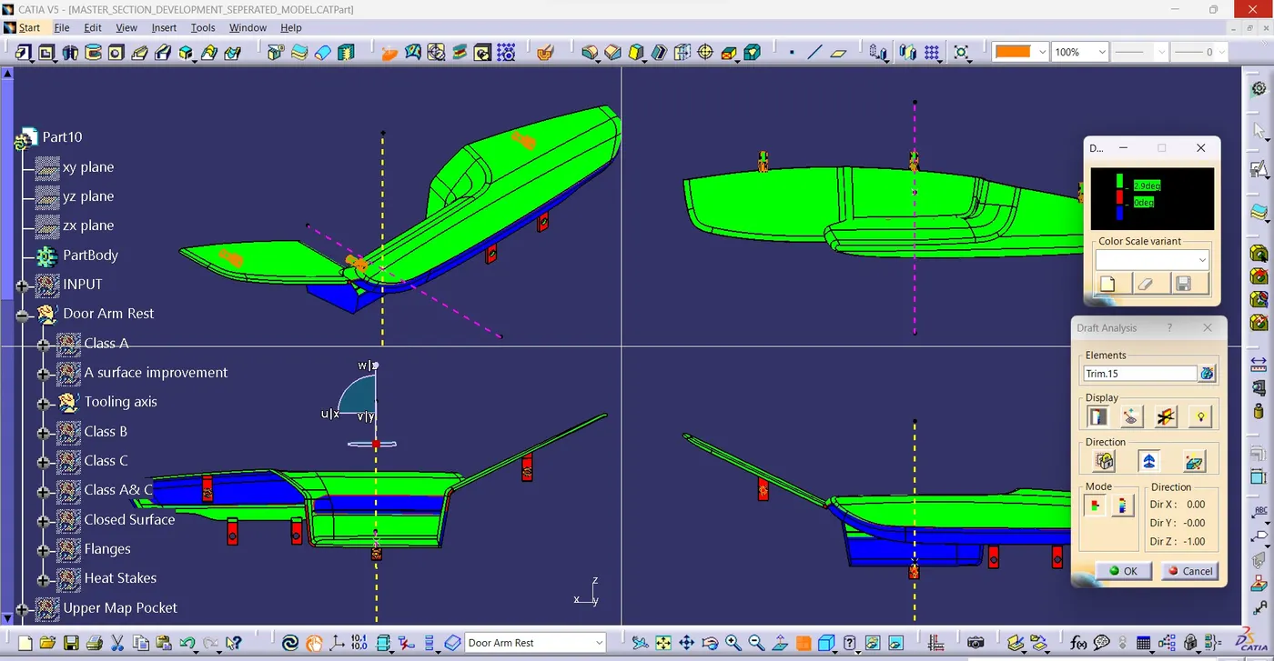
- Check the draft analysis considering the line as main tooling axis.The minimum draft of 3 degree is indicated by green,and less than 3 degree is indicated by red and negative draft by blue.
- It is found that the door arm rest cannot be cleared using tooling axis as it is a complicated surface.
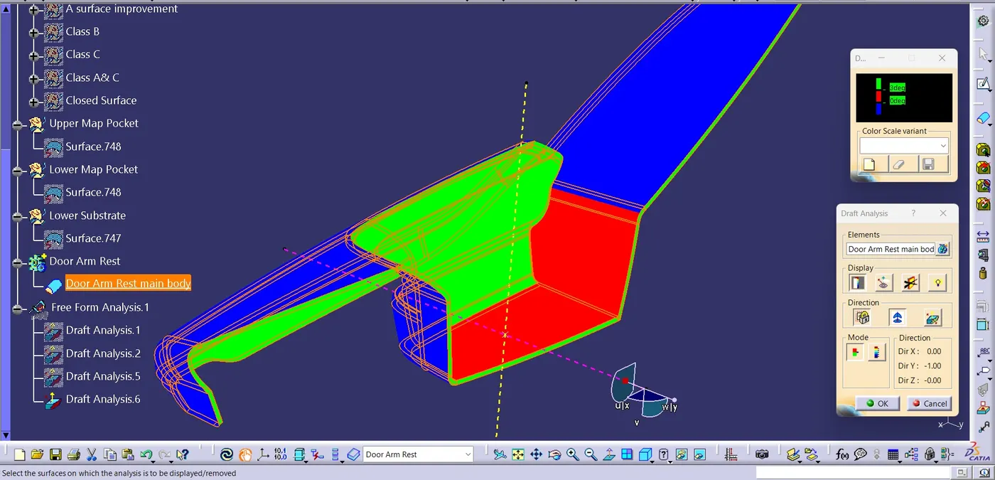
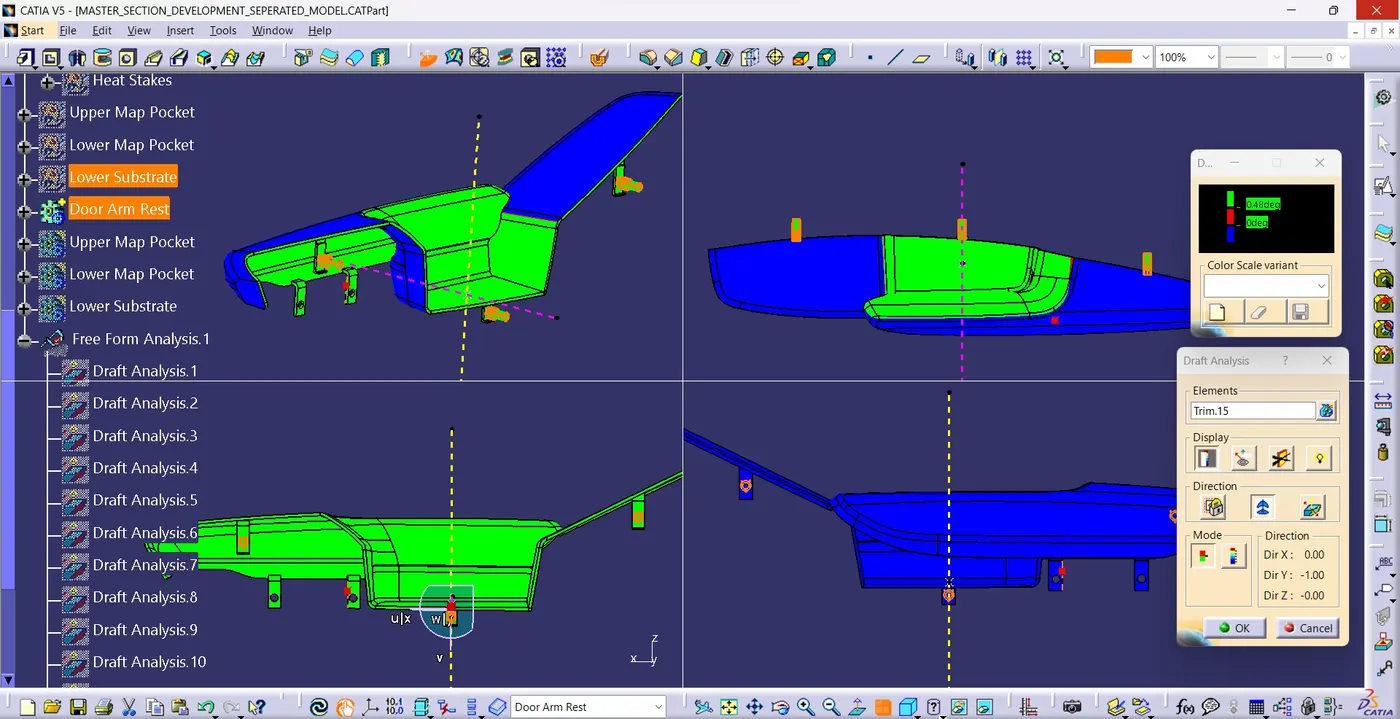
- So a side core axis is created along the Y axis and checked the draft analysis and found ok.
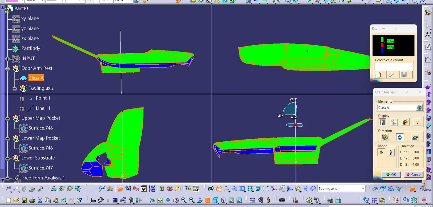
Most of the surfaces are clearing in the main tooling axis the rest surfaces need to be cleared in side core tooling axis.
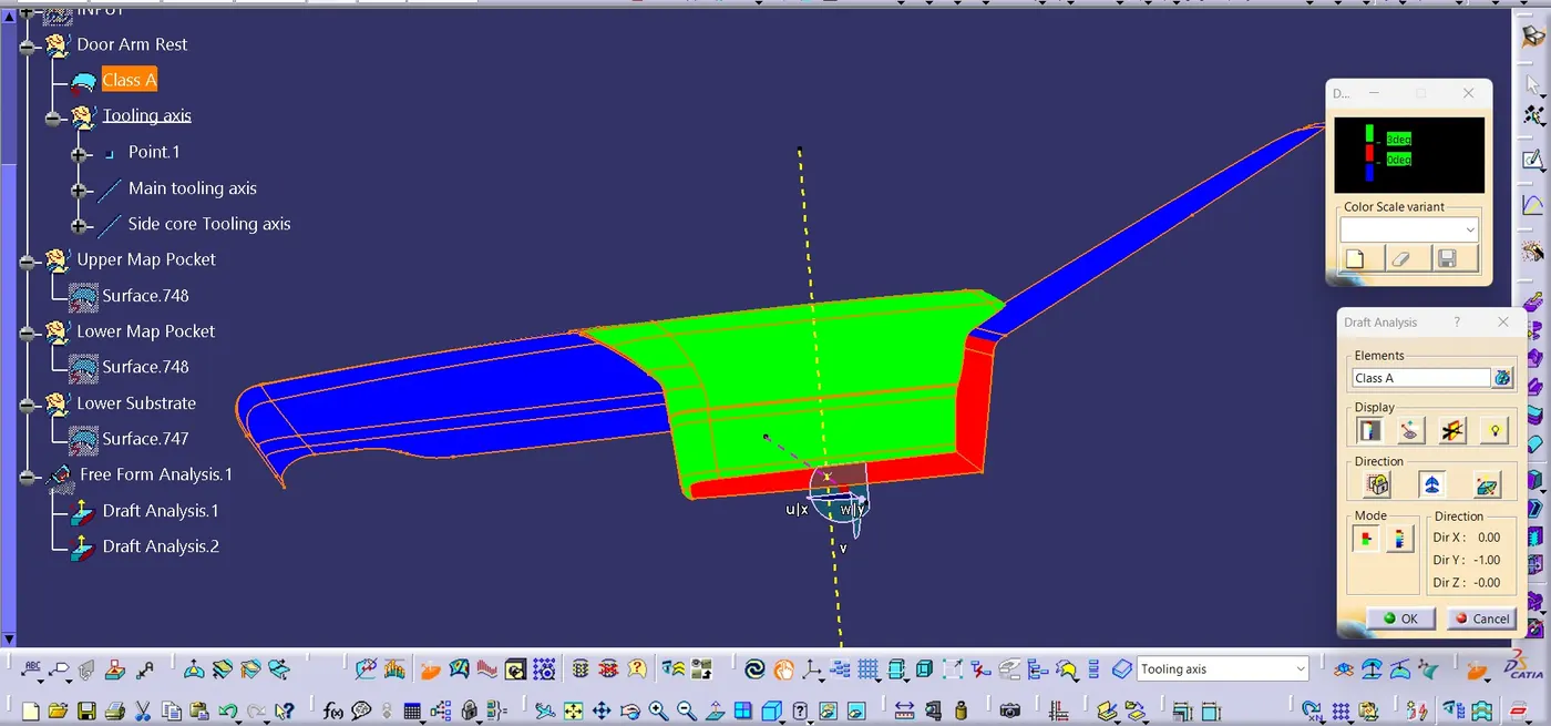
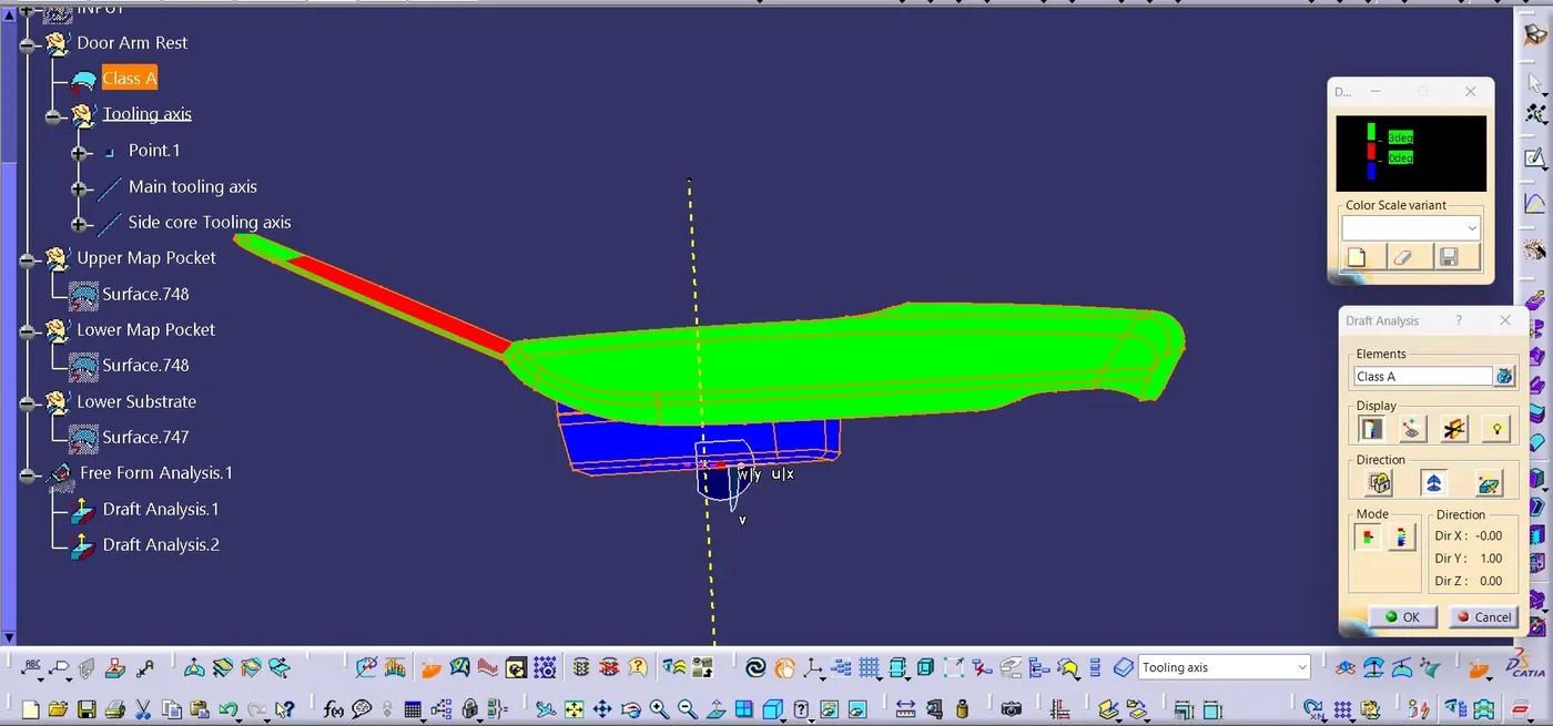
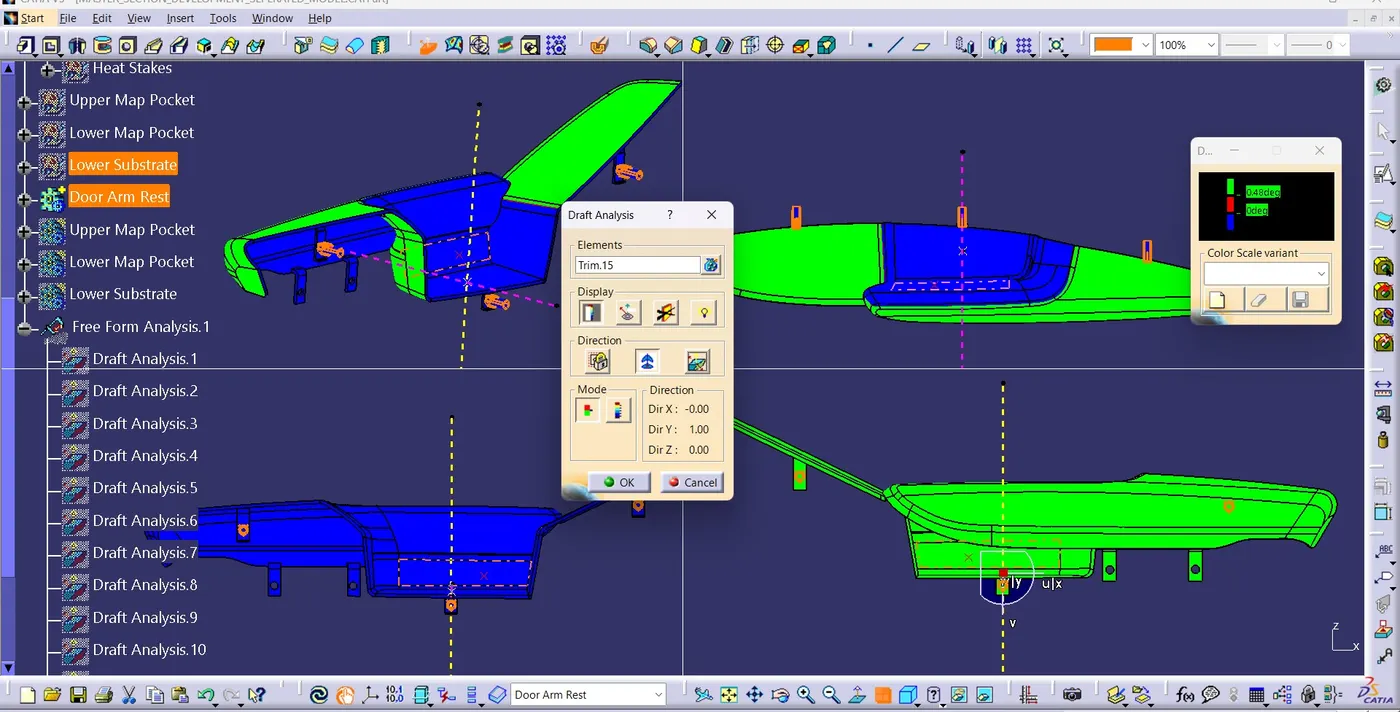
- By usign the side core tooling axis both the areas are clearing the draft of 3 degree
- The tooling has to be done from both sides (from +Y and -Y) of the tooling axis for clearing the surface.
Step 2 : Creating Class B surface
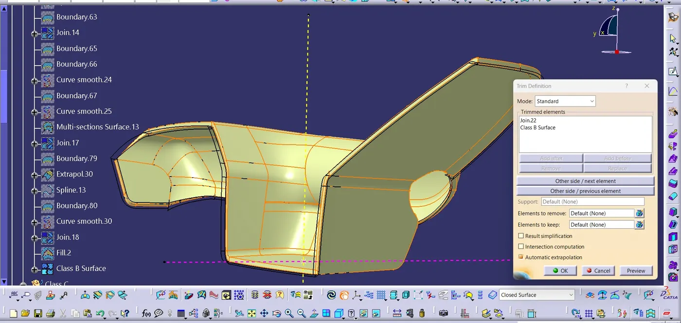
- Insert a geometrical set for creating Class B and Offset the class A for 2.5 mm.
- Create the missing patches and join to make the class B surface.
- To make the B surface extract,extrude,extrapolate,boundry,curve smooth,multi section surface commands were used.
- Extrapolate the boundry to make intersection with Class C surface.
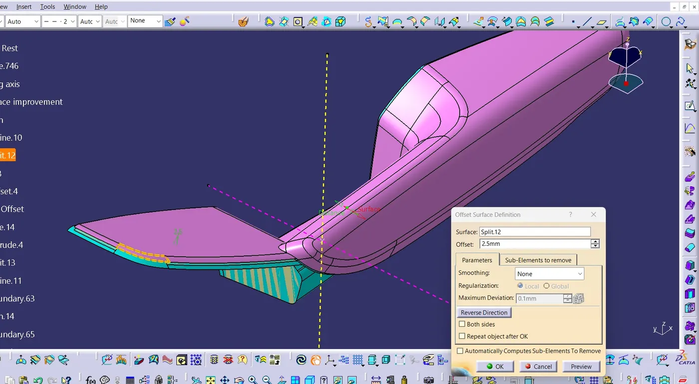
Class B surface of Door arm rest
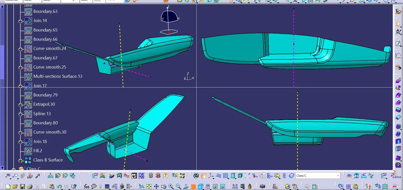
Step 3 : Creating Class C surface and joining it with Class A.
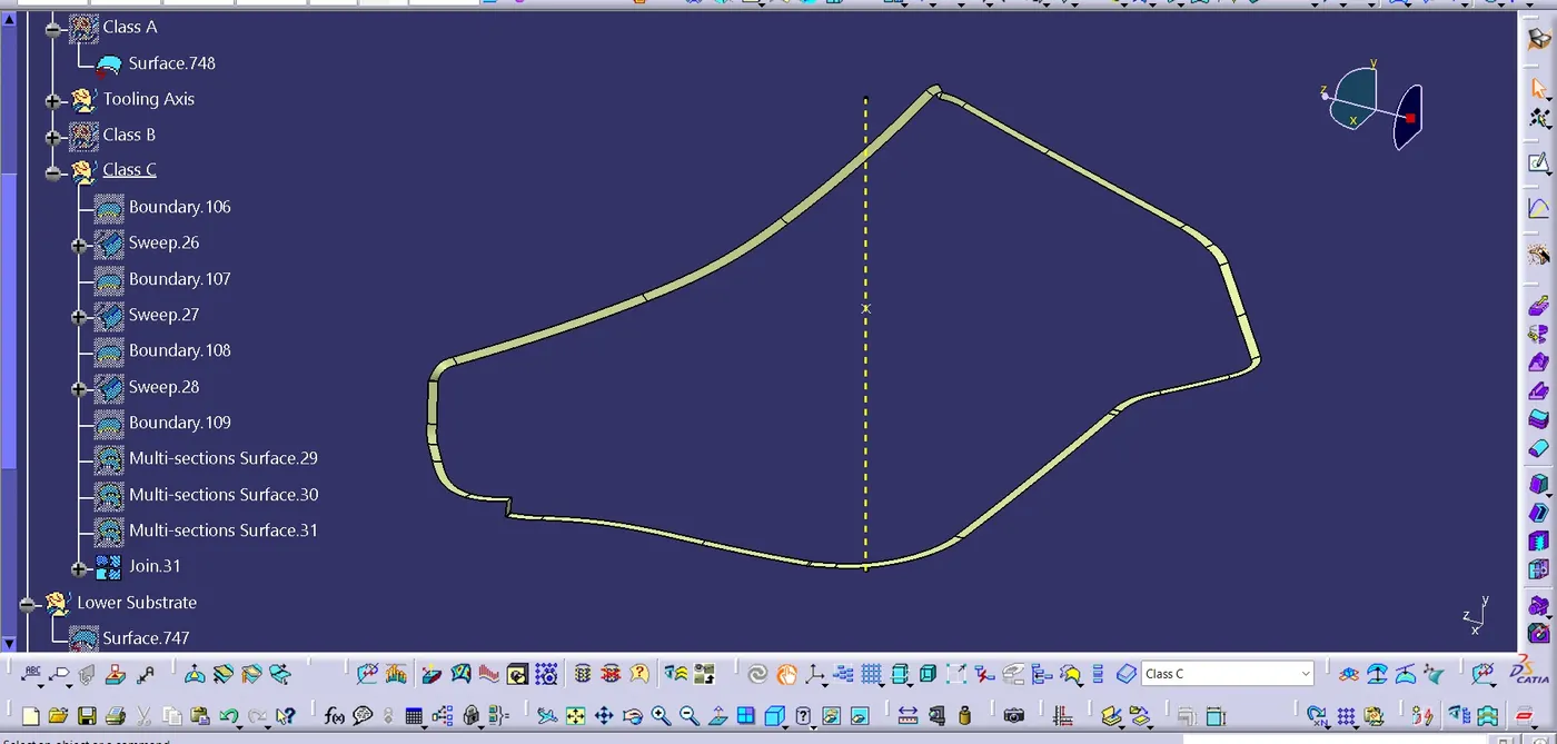
- Insert a geometrical set for class C surface creation.
- Using boundary,sweep,multi section surface,extrapolate,trim,join commands class C is created with a draft of 3 degree.
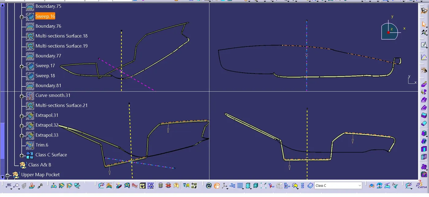
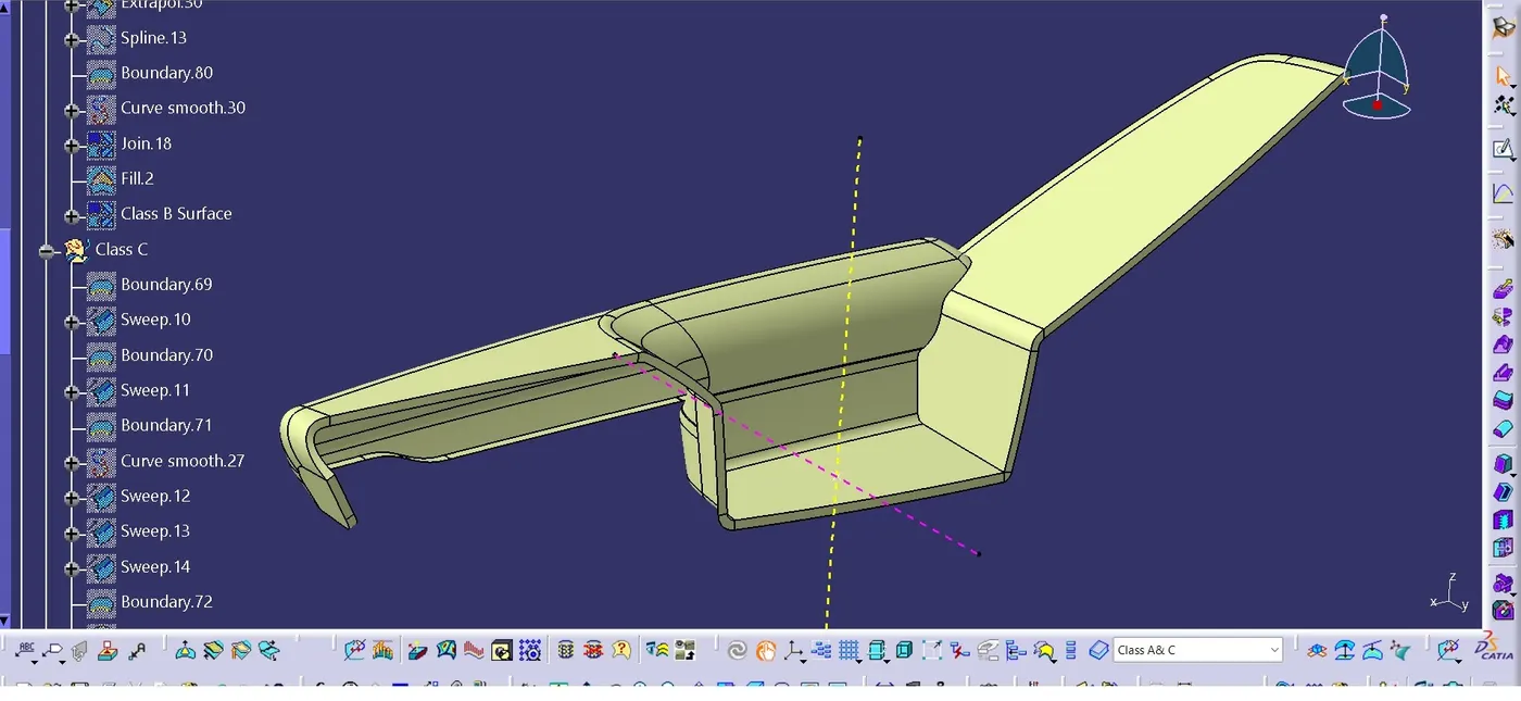
Step 4 : Creating closed surface and solid body of door arm rest
- Create closed surface by trimming Class A & C with Class B
- Switch to part design and using 'closed surface command make the solid body of door arm rest
- After makeing the solid body conducted the draft analysis.
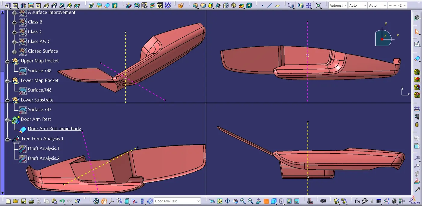
Draft analysis on main tooling axis
Draft analysis along side core tooling axis front and back.
Component 2 : Upper Map Pocket
Step 5 : Creating Upper Map pocket as same as the door arm rest.
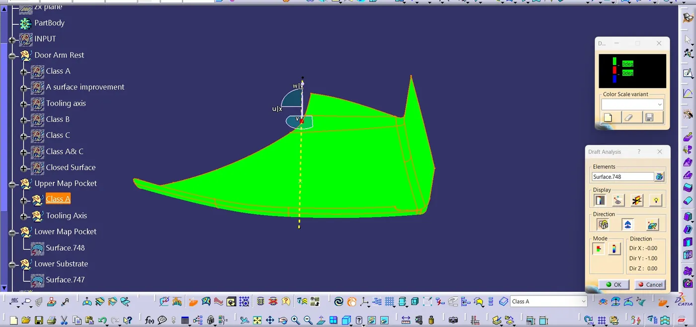
- The main tooling axis is selected along Y direction and the draft analysis was conducted and confirmed.
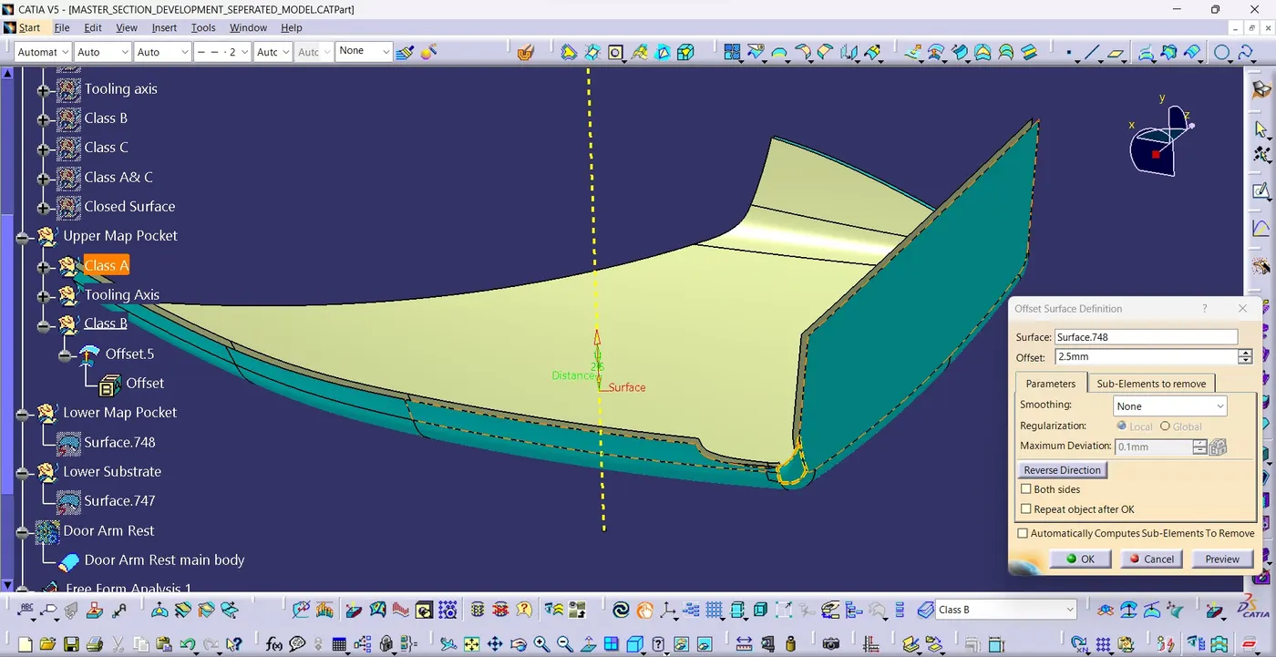
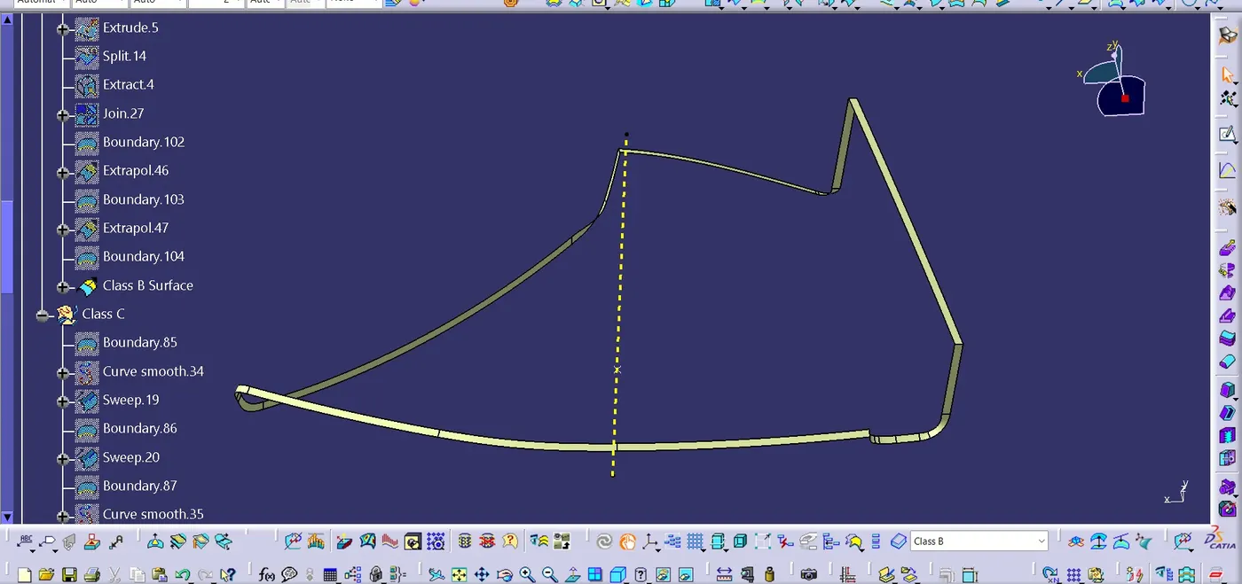
- Insert a geometrical set for creating Class B and Offset the class A for 2.5 mm.
- Create the missing patches and join to make the class B surface.
- Extrapolate the boundary so to make intersection with class C.
Class B surface
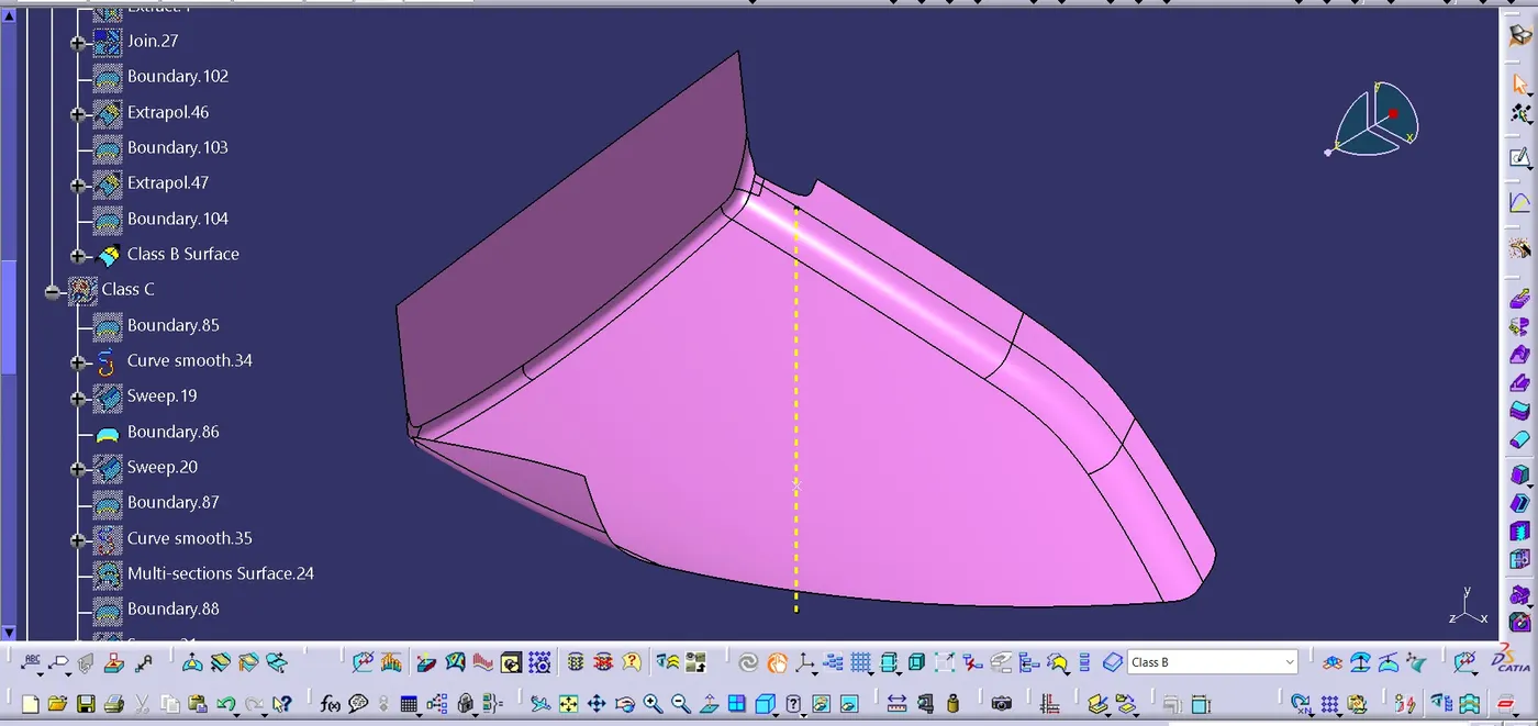
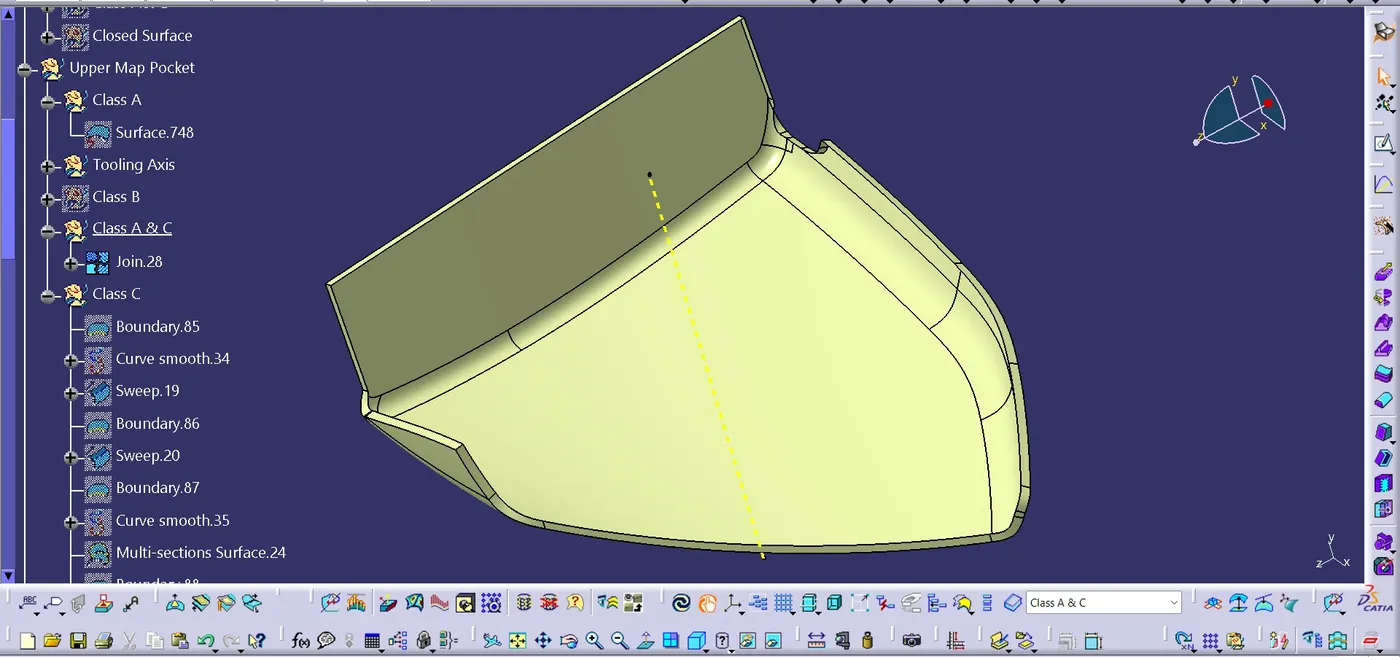
- Create the Class C Surface using sweep with a draft of 3 degree with the main tooling axis
- Using join command joined the Class A with Class C.
Class A & C
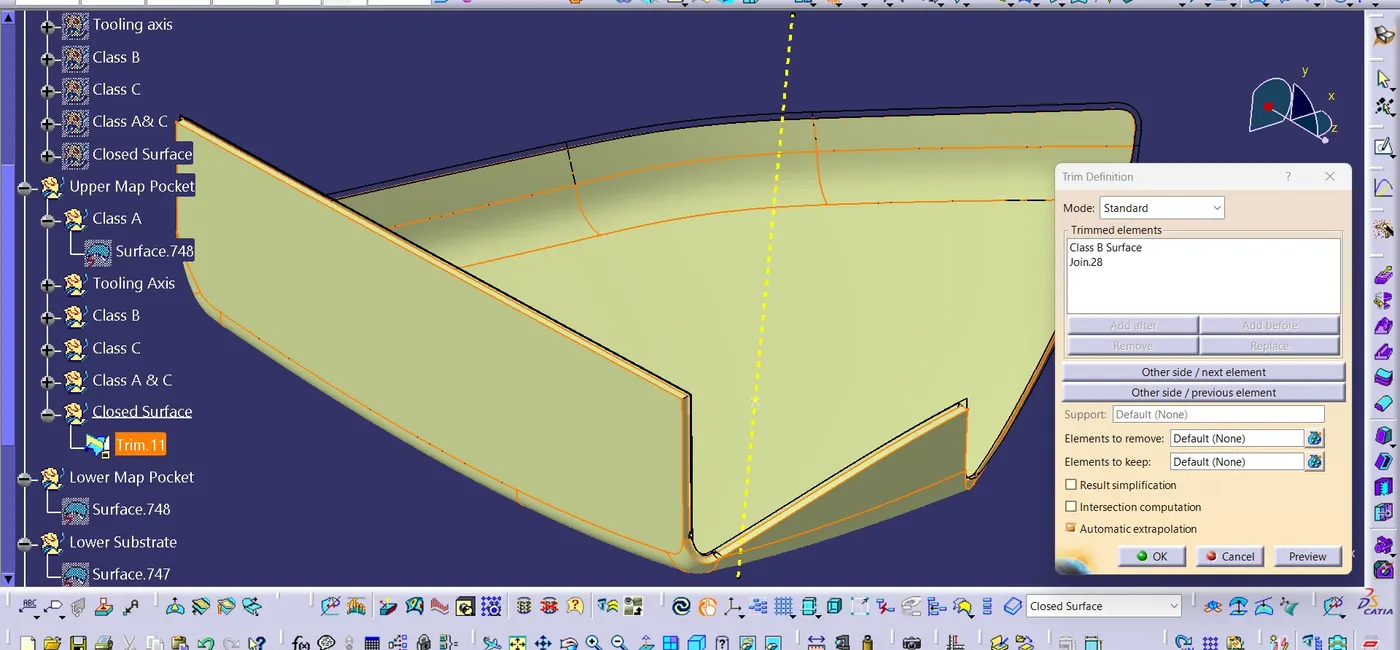
- Trim the Class B with Class A & C to get the closed surface.
- Switching to part workbench and insert part body, then using 'Close Surface' command the solid part of Upper Map Pocket is made.
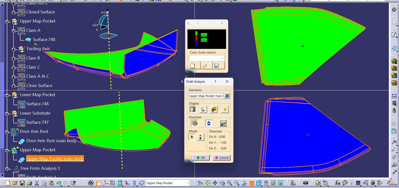
- Then coduct the draft analysis.
Closed surface
Upper Map Pocket part body
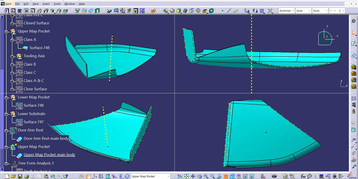
Draft analysis
Component 3 : Lower Map Pocket
Step 6 : Create Lower Map pocket.
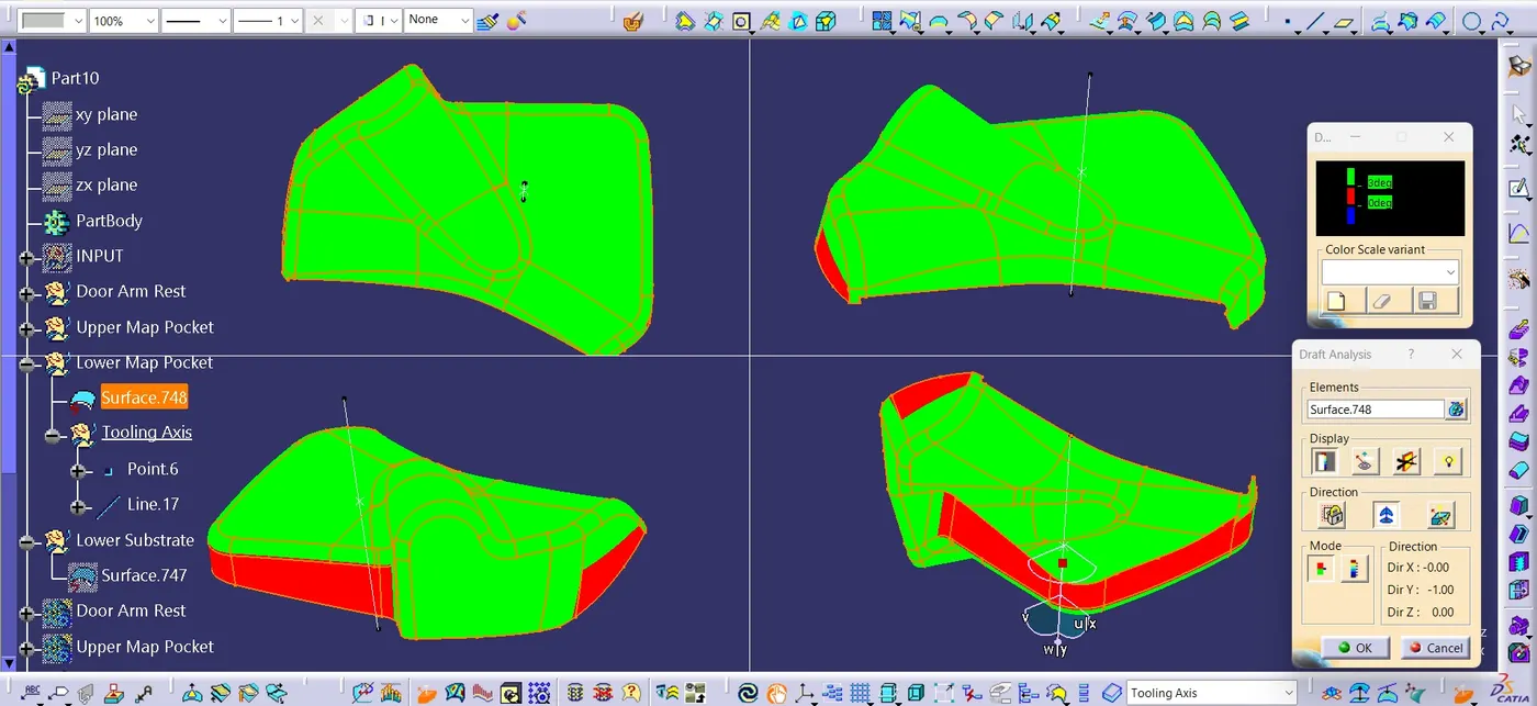
- The main tooling axis is selected along Y direction and the draft analysis was conducted.
- It was found that most ot surface is clearing the draft but two sides some areas which are opposite to eachother is not properly clearing 3 degree, both sides show 0 degree draft.
- The analysis results has to be shared with A surface designer and request for improvement.
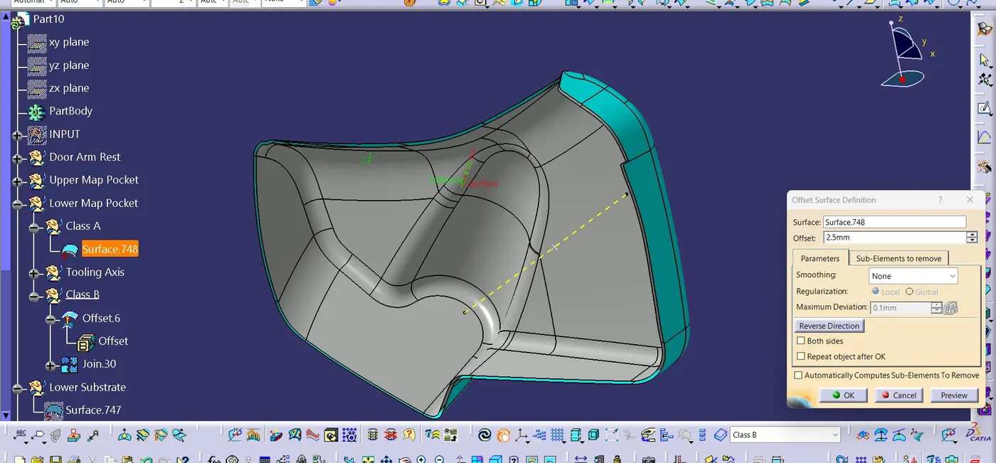
- Insert a geometrical set for creating Class B and Offset the class A for 2.5 mm.
- Check for any missing patches,if any patches are missing create them and join to main.
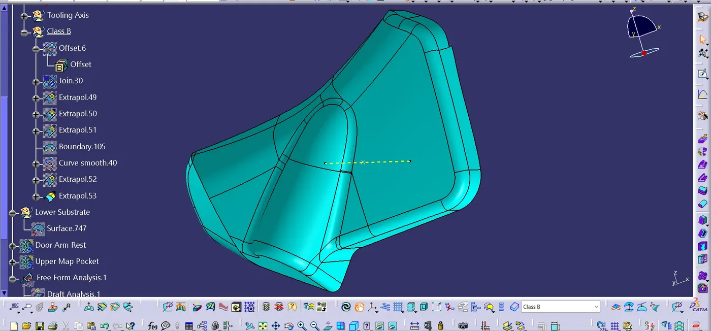
- Create the Class C Surface using sweep with a draft of 3 degree with the main tooling axis
- Using join command joined the Class A with Class C.
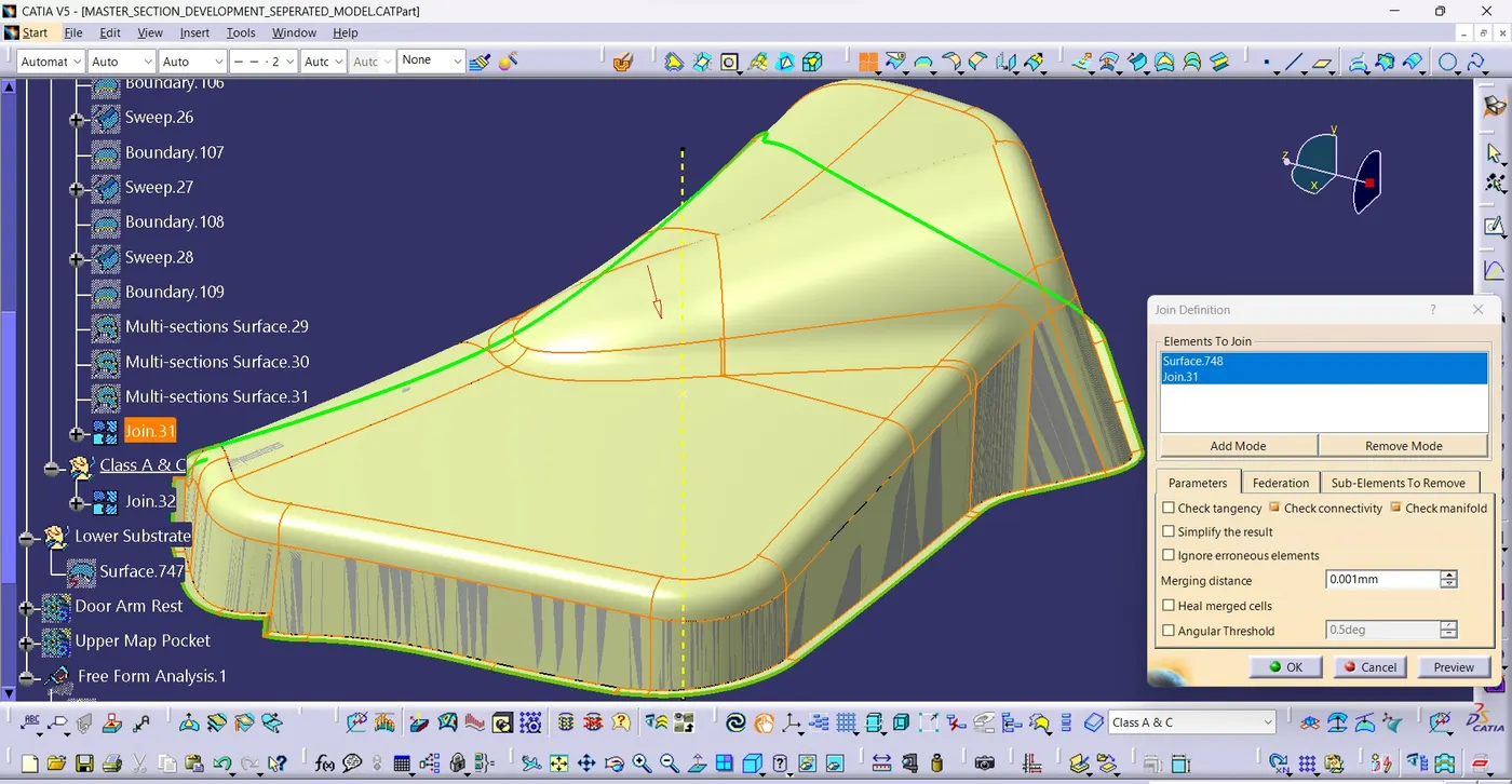
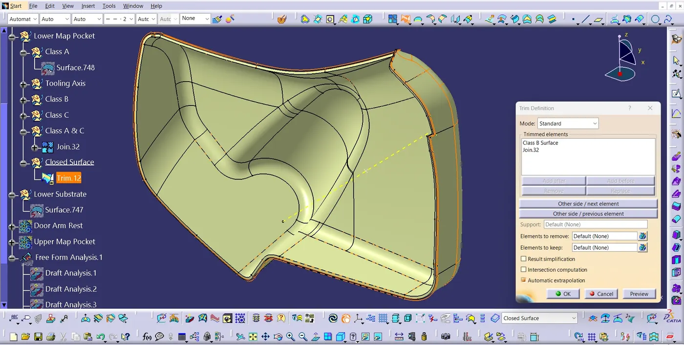
- Trim the Class B with Class A & C to get the closed surface.
- Switching to part workbench and insert part body, then using 'Close Surface' command the solid part of Lower Map Pocket is made.
- Then conduct the draft analysis.
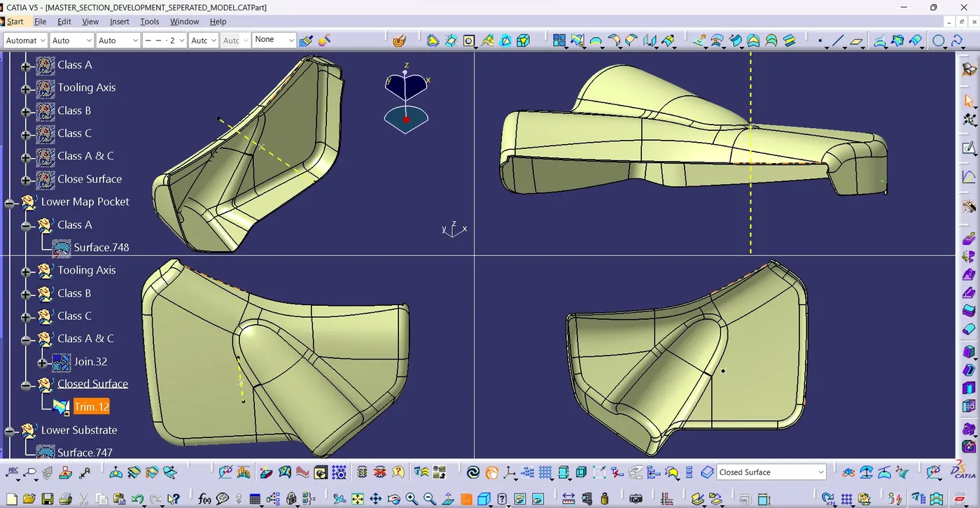
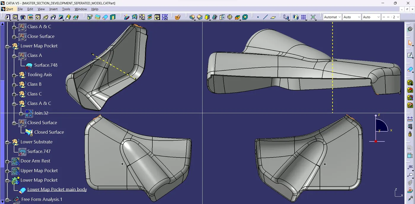
Lower Map Pocket Solid
Draft Analysis
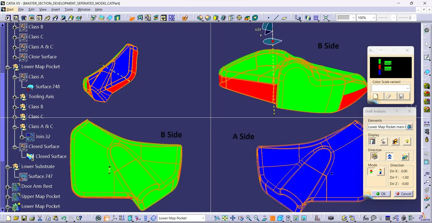
From the draft analysis it is found that most of the areas are clearing the 3 degree draft, but as we found in class A analysis some areas are having 0 degree draft.
Component 4 : Lower Substrate
Step 7 : Create the Lower Substrate
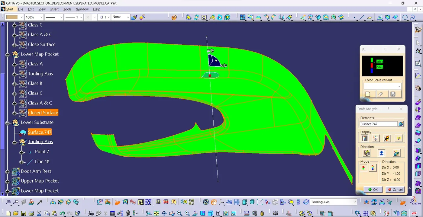
- The main tooling axis is selected along Y direction and the draft analysis was conducted.Found the surface is clearing the draft with the tooling axis, hence it is the main tooling axis.
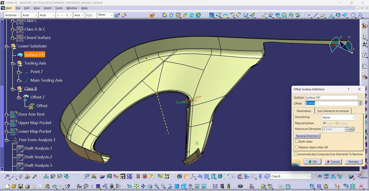
- Create Class B Surface by offsetting the Class A to the thickness of body 2.5 mm
- After offsetting clear the missing patches if any.
- Extrapolate the boundary inorder to intersect with the Class A & C
- Trim the Class B with Class A & C to get the closed surface.
- Switching to part workbench and insert part body, then using 'Close Surface' command the solid part of Lower Map Pocket is made.
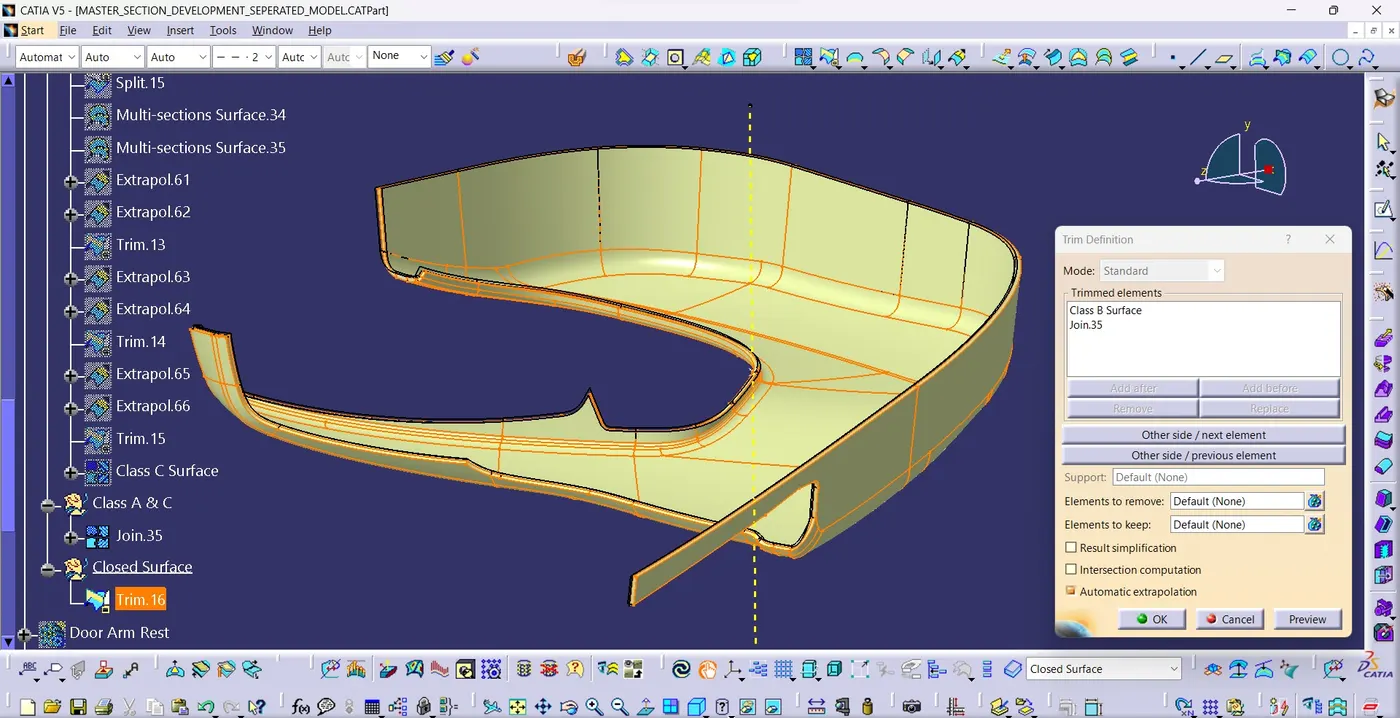
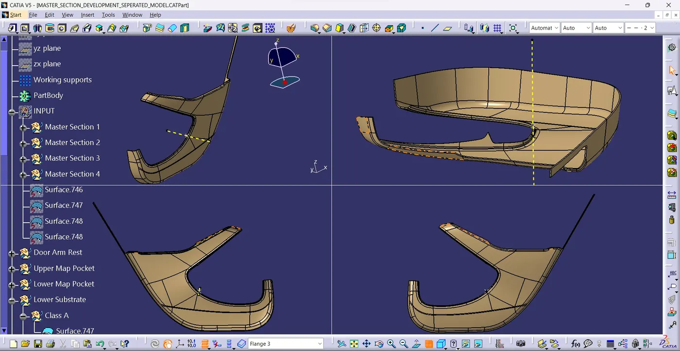
Lower Substrate with edge flanges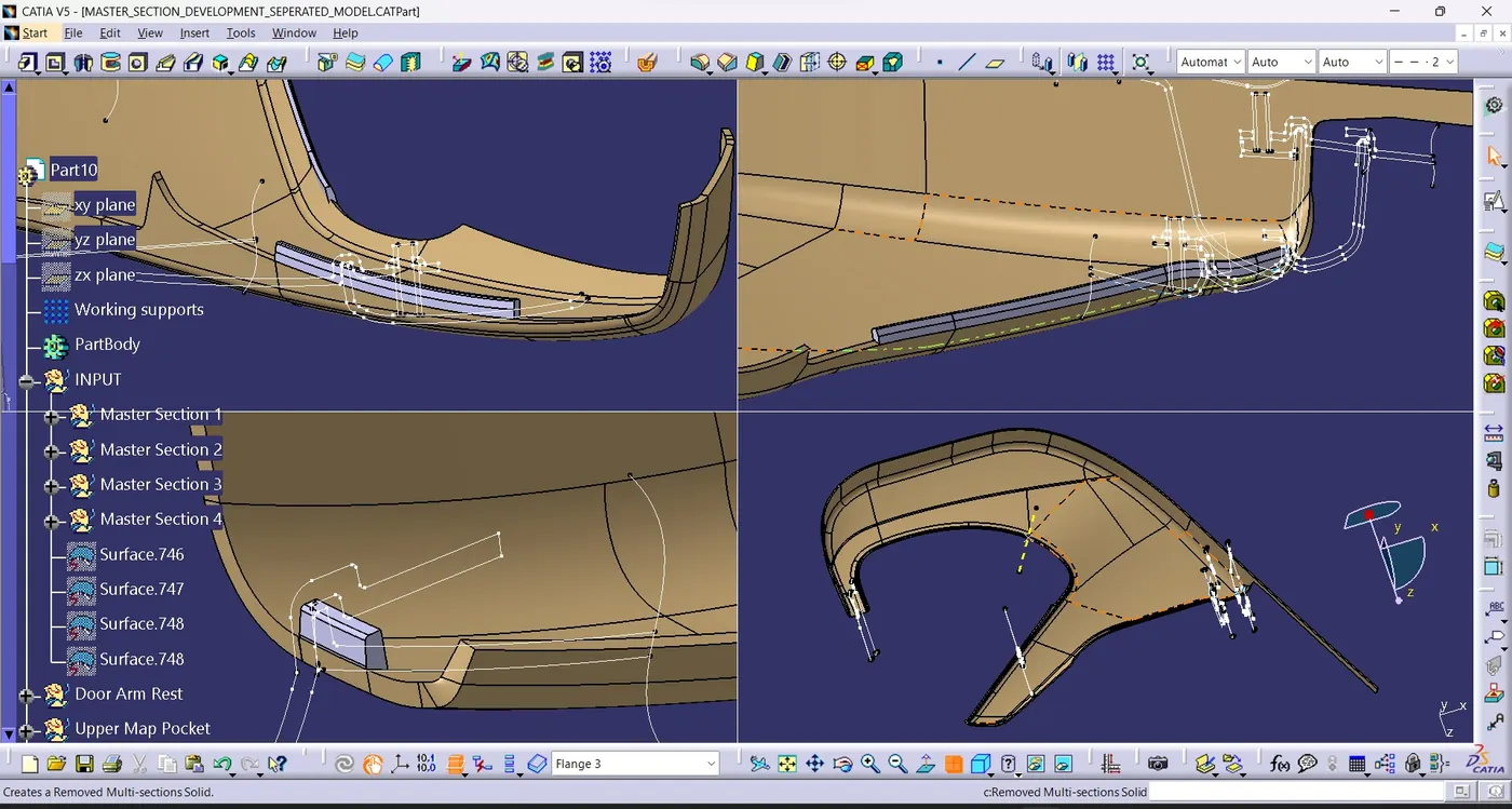
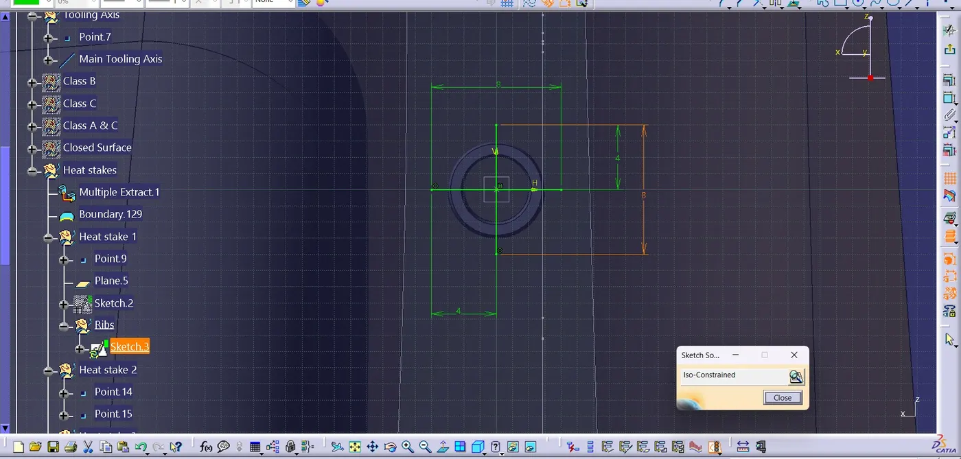
Step 8 : Construct the heat stakes for the lower substrate as per design specifications and master section.
- Insert a geometrical set for creating the sketch, make the sketch for the heat setakes.
- Extrude the sketch using pad command and give draft of 0.5 degree.
- Make the sketch for rib and pad it and gibe fillet and chamfer. Union trim it with the heat stake.
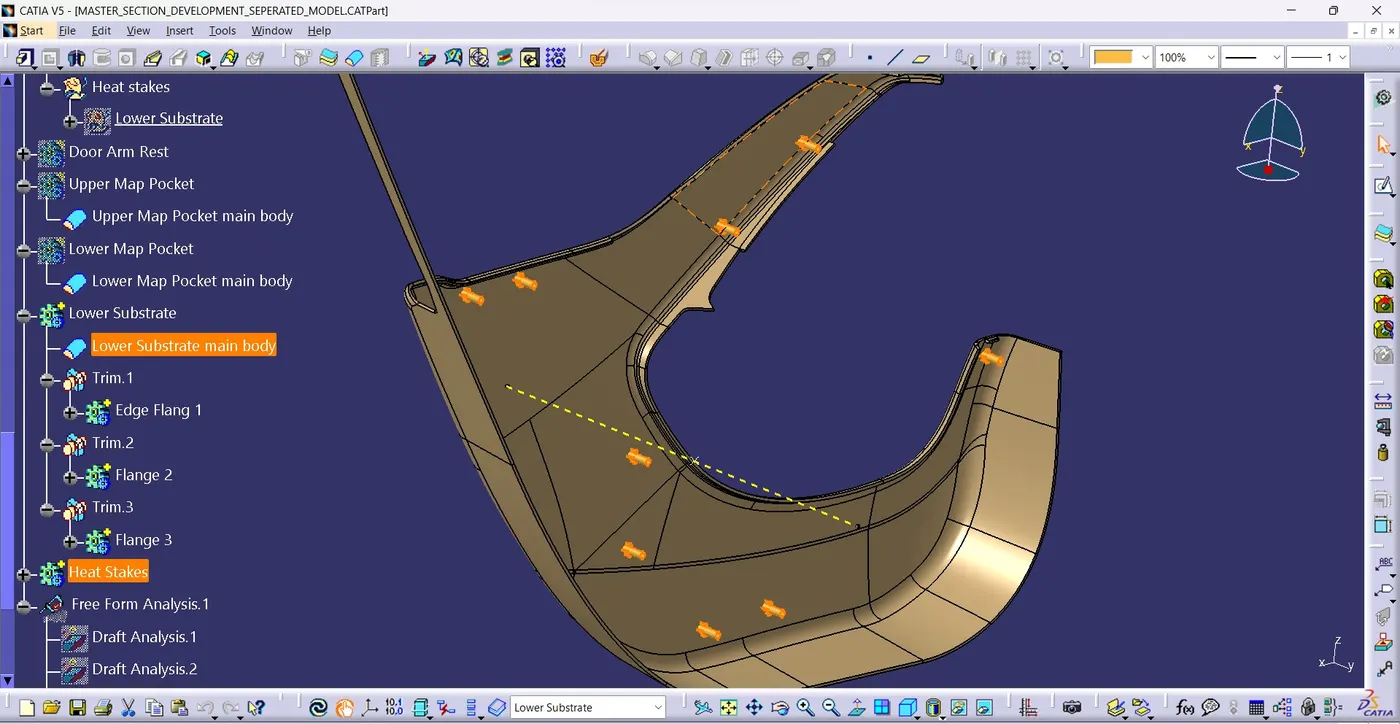
- Copy and translate the heat stake made to requried locations.
- Wall thickness of heat stake = 2.5 * 0.4 = 1 mm
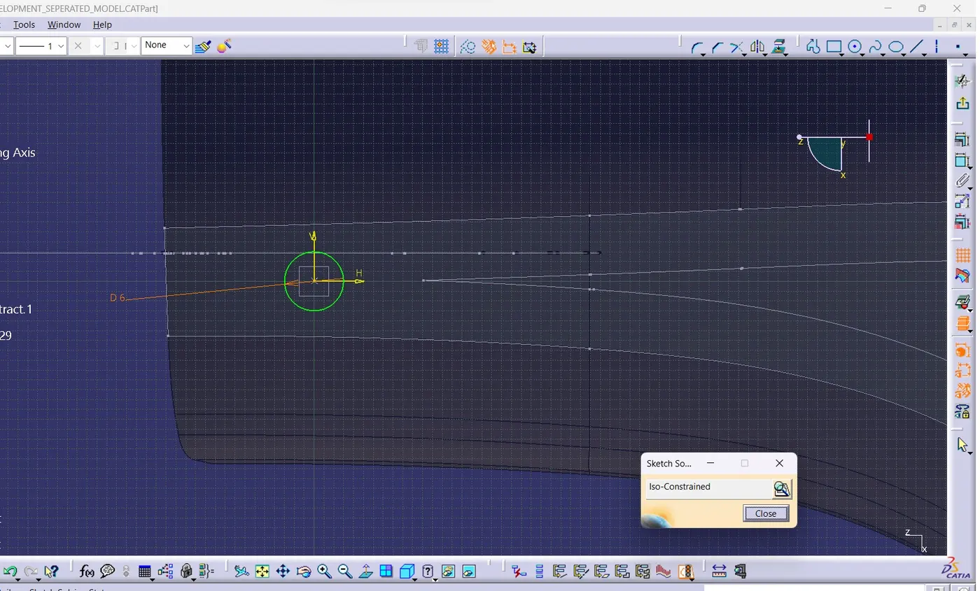
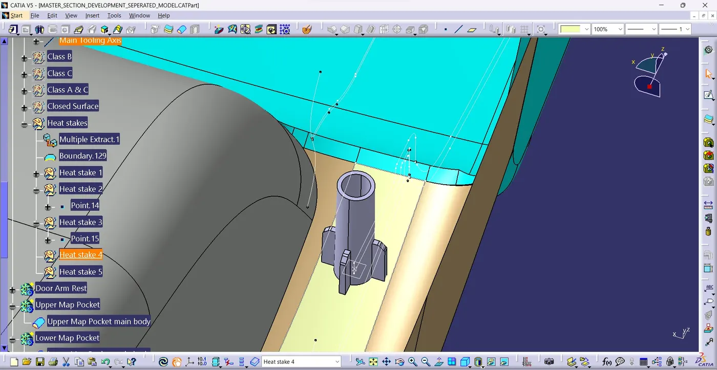
Lower Substrate With heat stakes
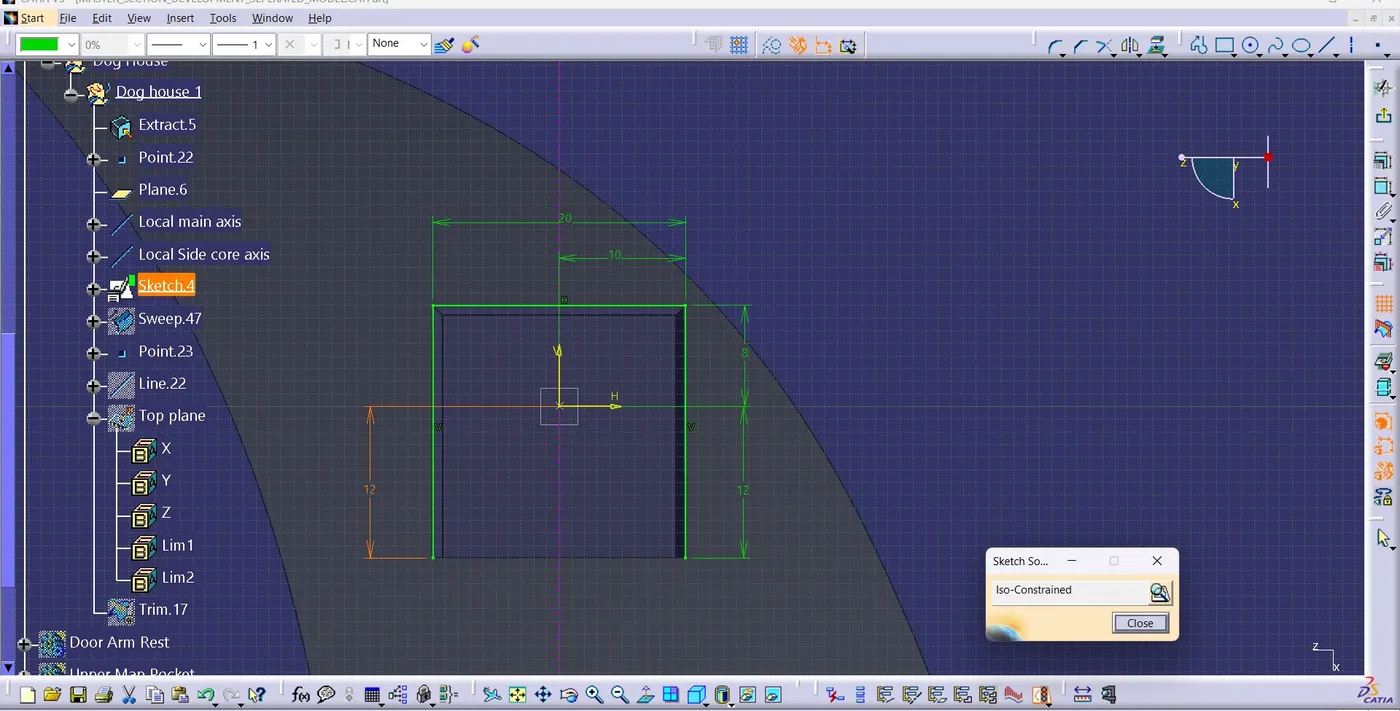
Step 9 : Construct the Dog house
- Insert geometrical set for creating doghouse.
- Make a side core tooling axis for providing draft.
- Extract the surface and add a point and plane on it to make sketch which will be extruded and thickned.
- Provide draft of 1.5 degree for the outer surface with main tooling axis and 0.5 degree for inside surface with side core tooling axis of the doghouse.
- Provide the edge fillets.
- Create the slot for push pin and screw/bolt by padding.
- Join the dog house using union trim to the main body and remove the slot.
Design Criteria
- C thickness should be 40% of the main wall thickness T
- Minimum width of the dog house is 12 mm.
- Height of B should be 3-6 mm
- Minimum draft for the do house is 1.5 degree to tooling axis.
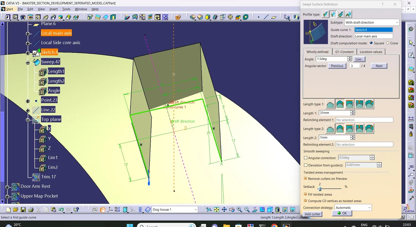
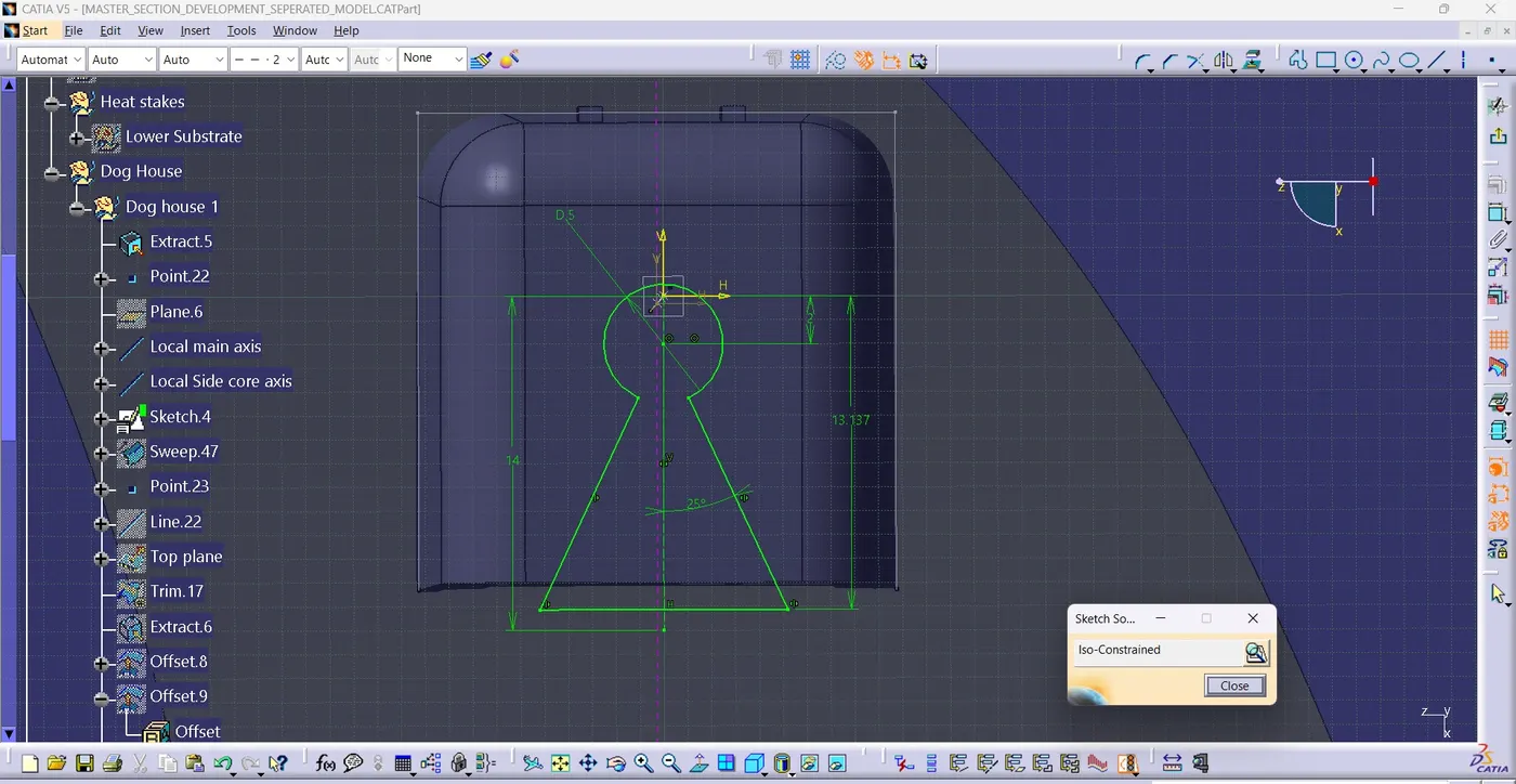
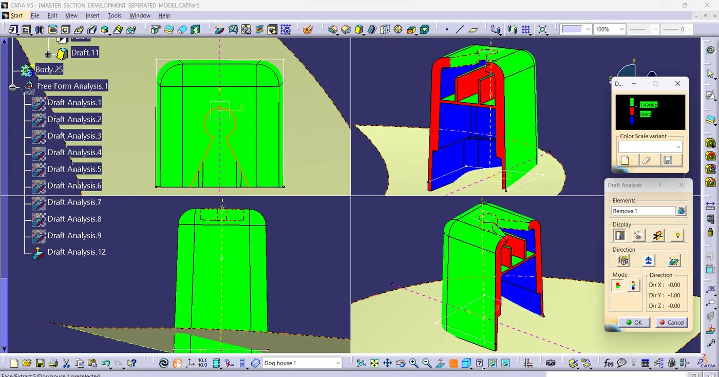
Step 10 : After completing all the B side feactures for Lower substrate do the draft analysis
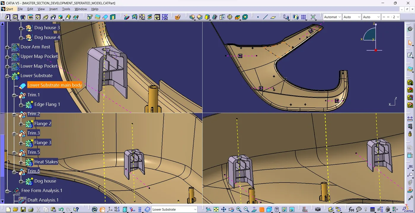
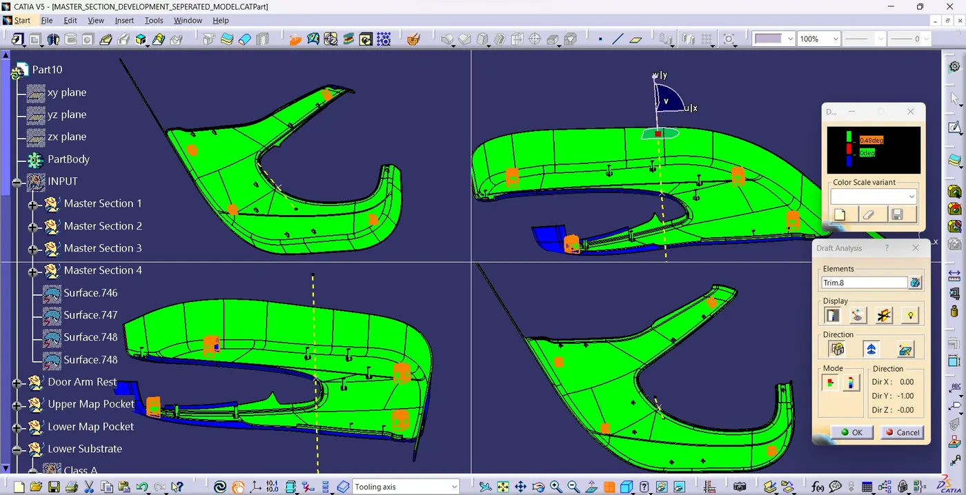
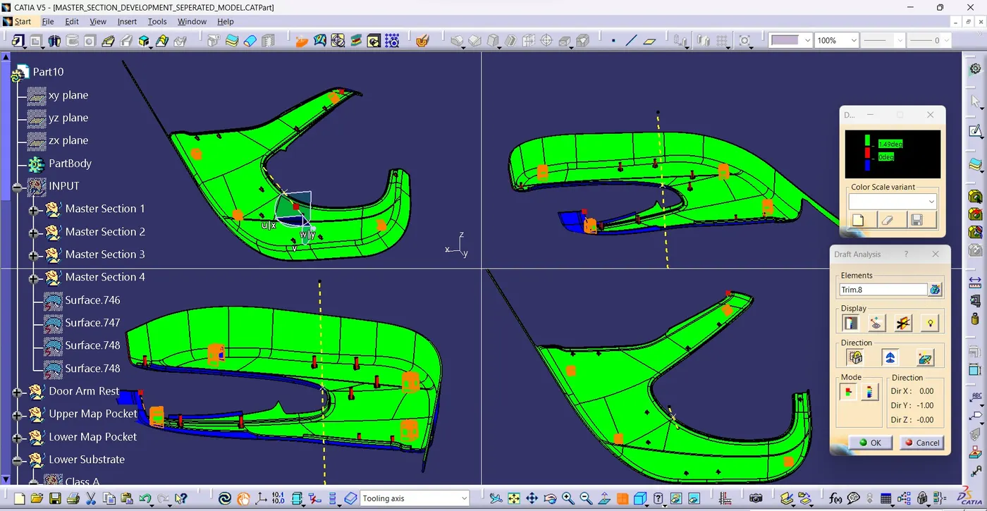
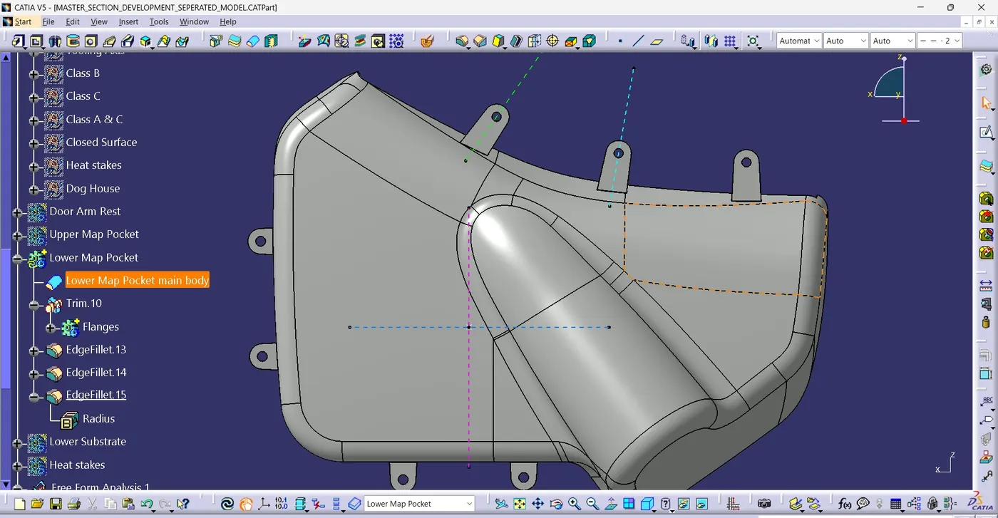
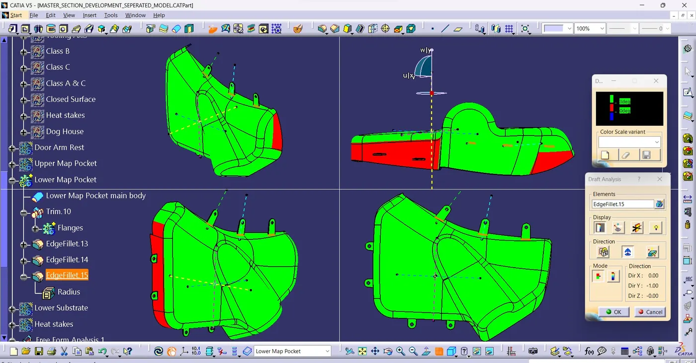
Step 11 : Add flanges to lower map pocket for heat stakes and conduct draft analysis.
Step 12 : Create Flanges for Upper Map Pocket by taking dimensions from Master sections.
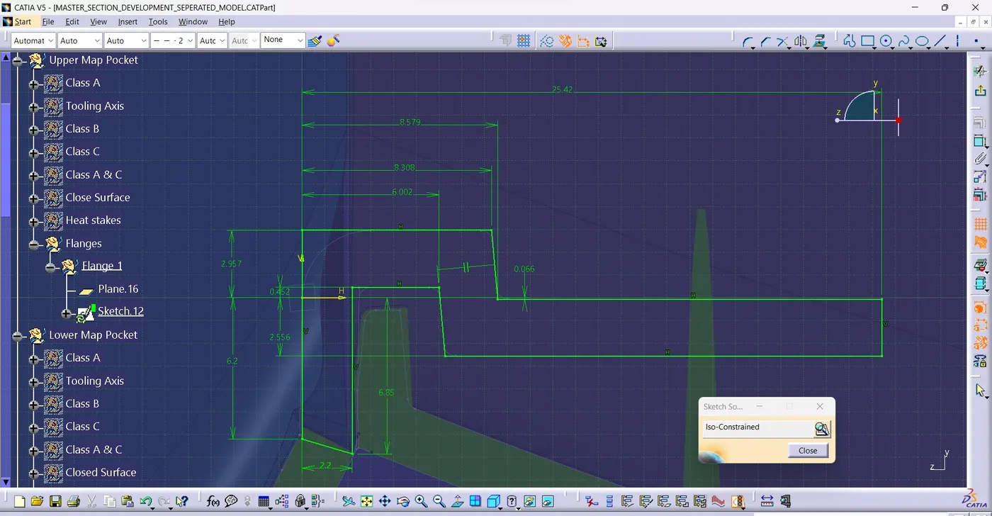
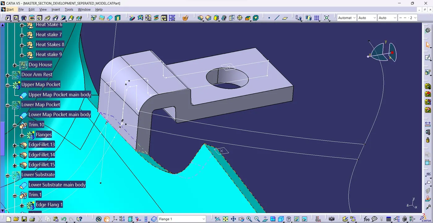
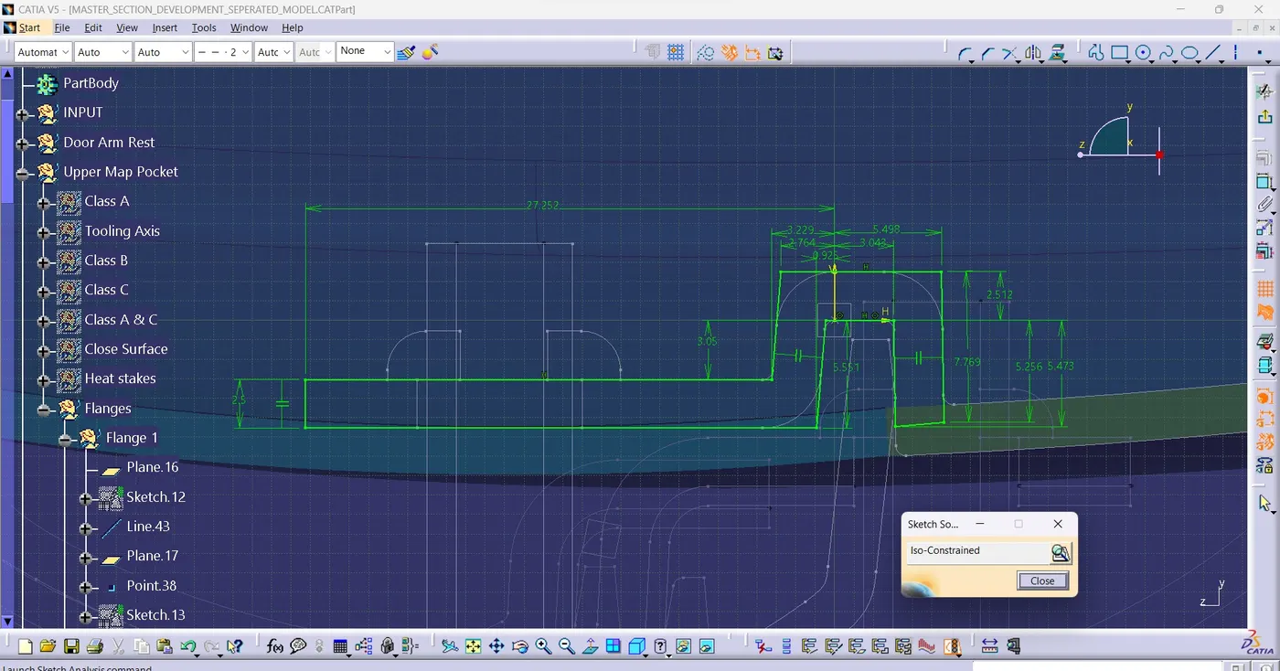
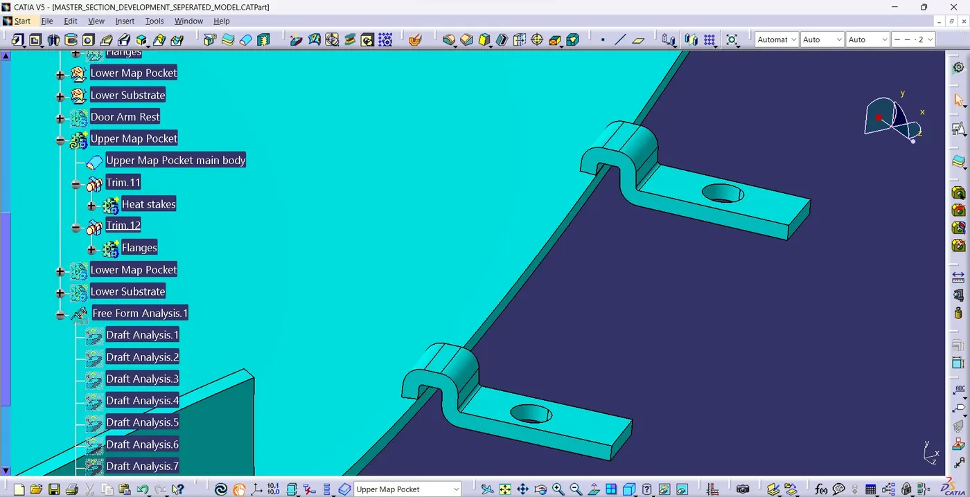
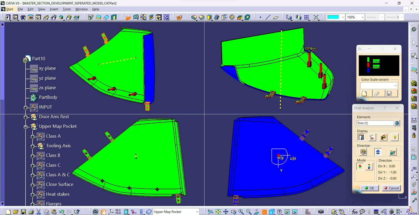
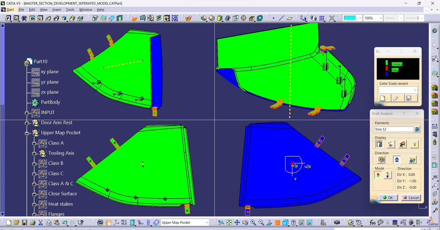
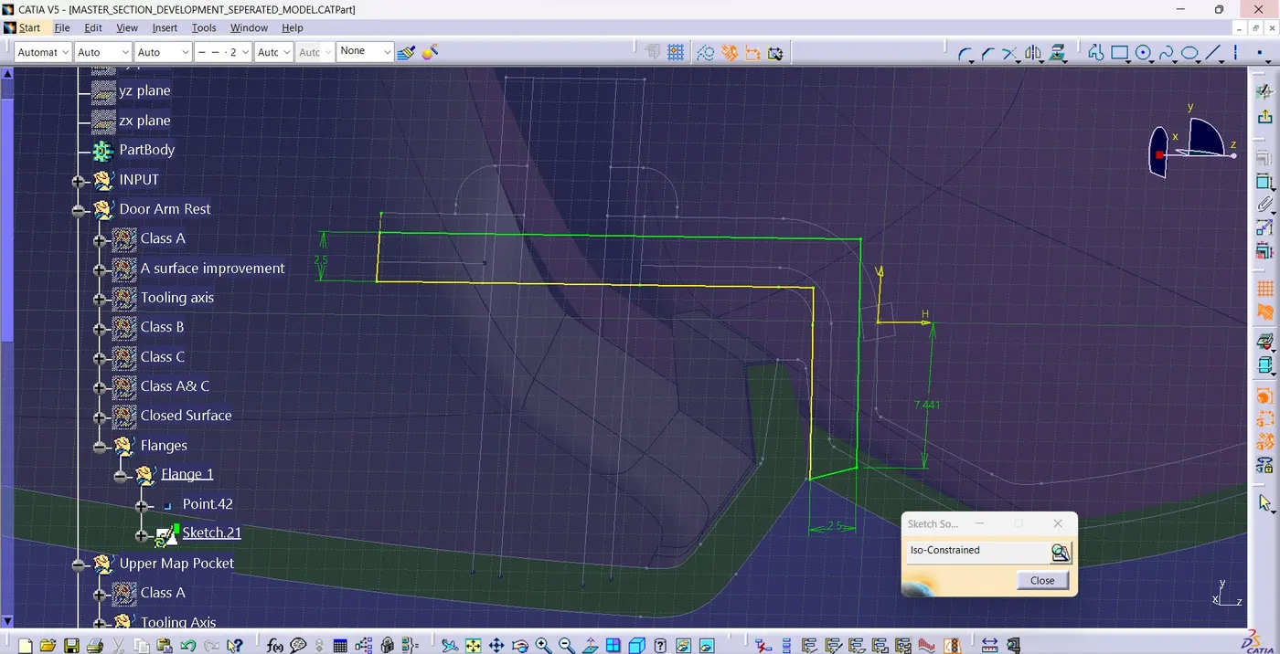
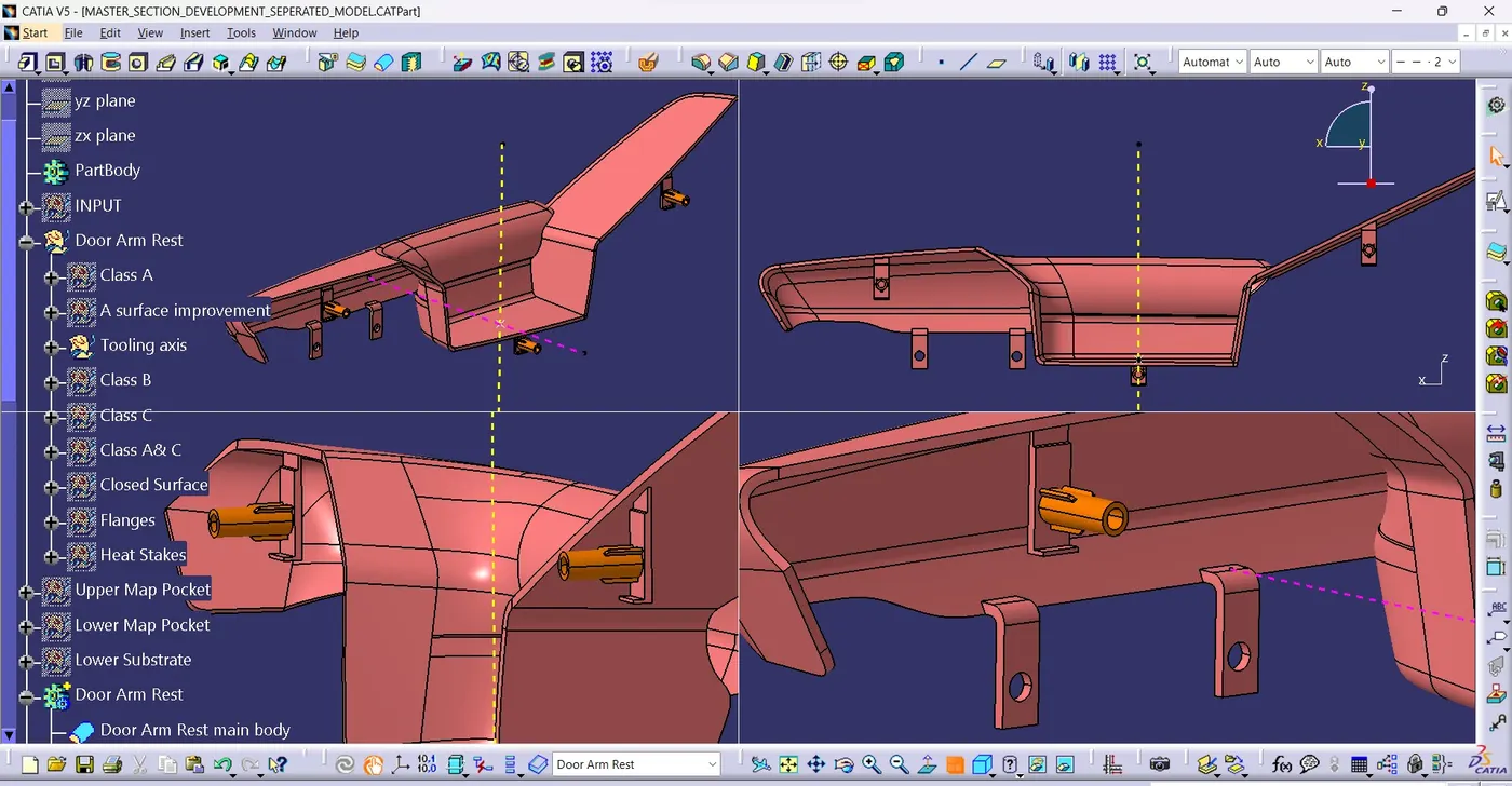
Step 13 : Create flanges and heat stakes for the Door Arm Rest by taking dimensions from the master section and conduct draft analysis.
Door Arm Rest with all B side features :
Draft analysis
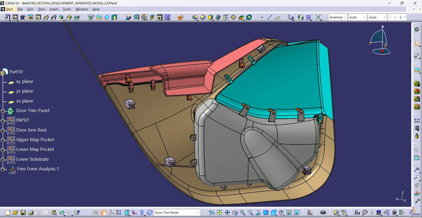
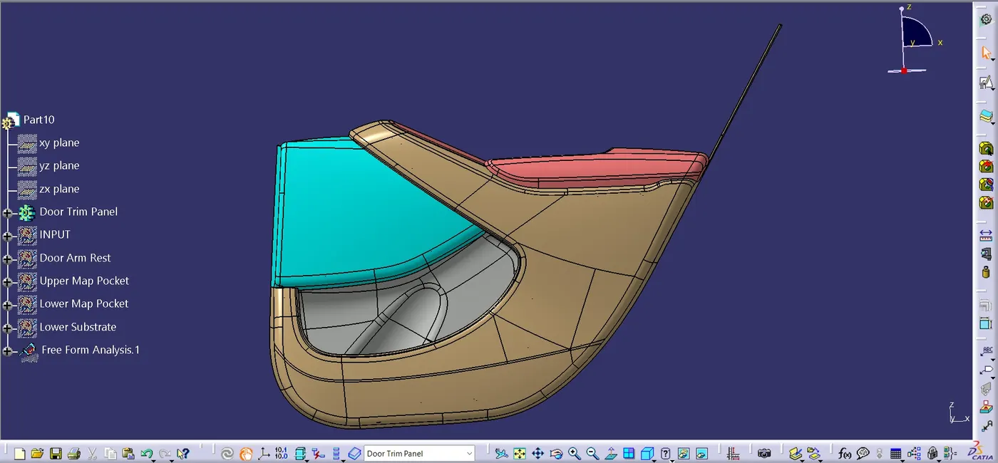
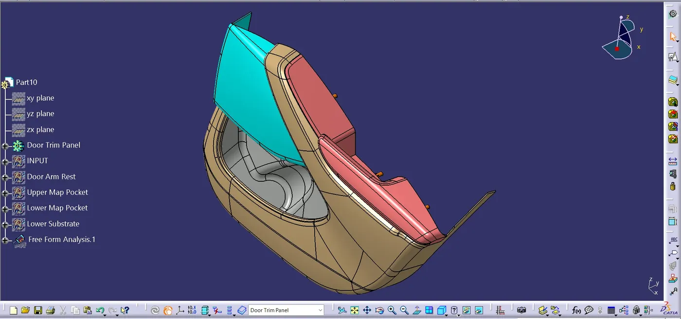
Completed Door Trim panel
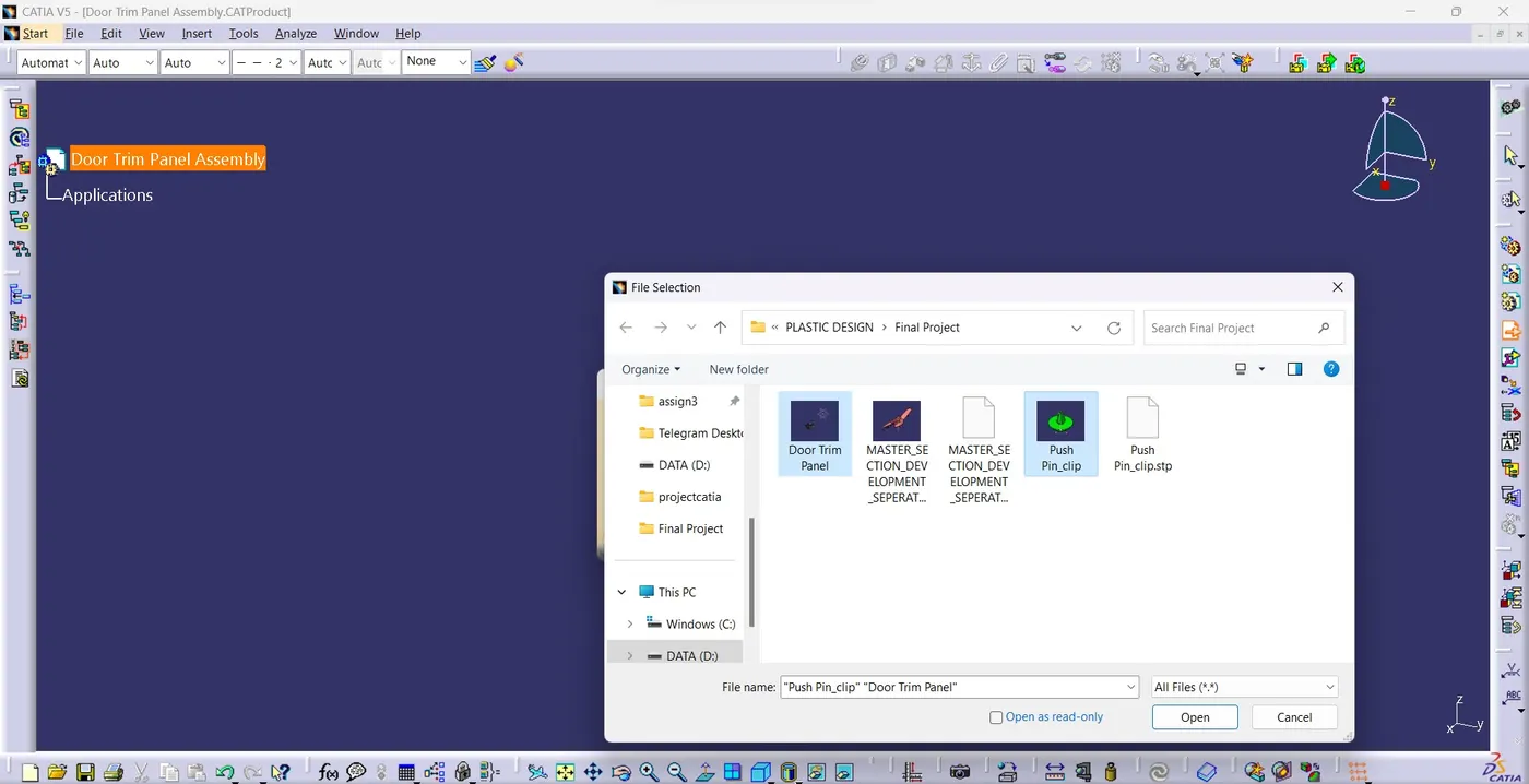
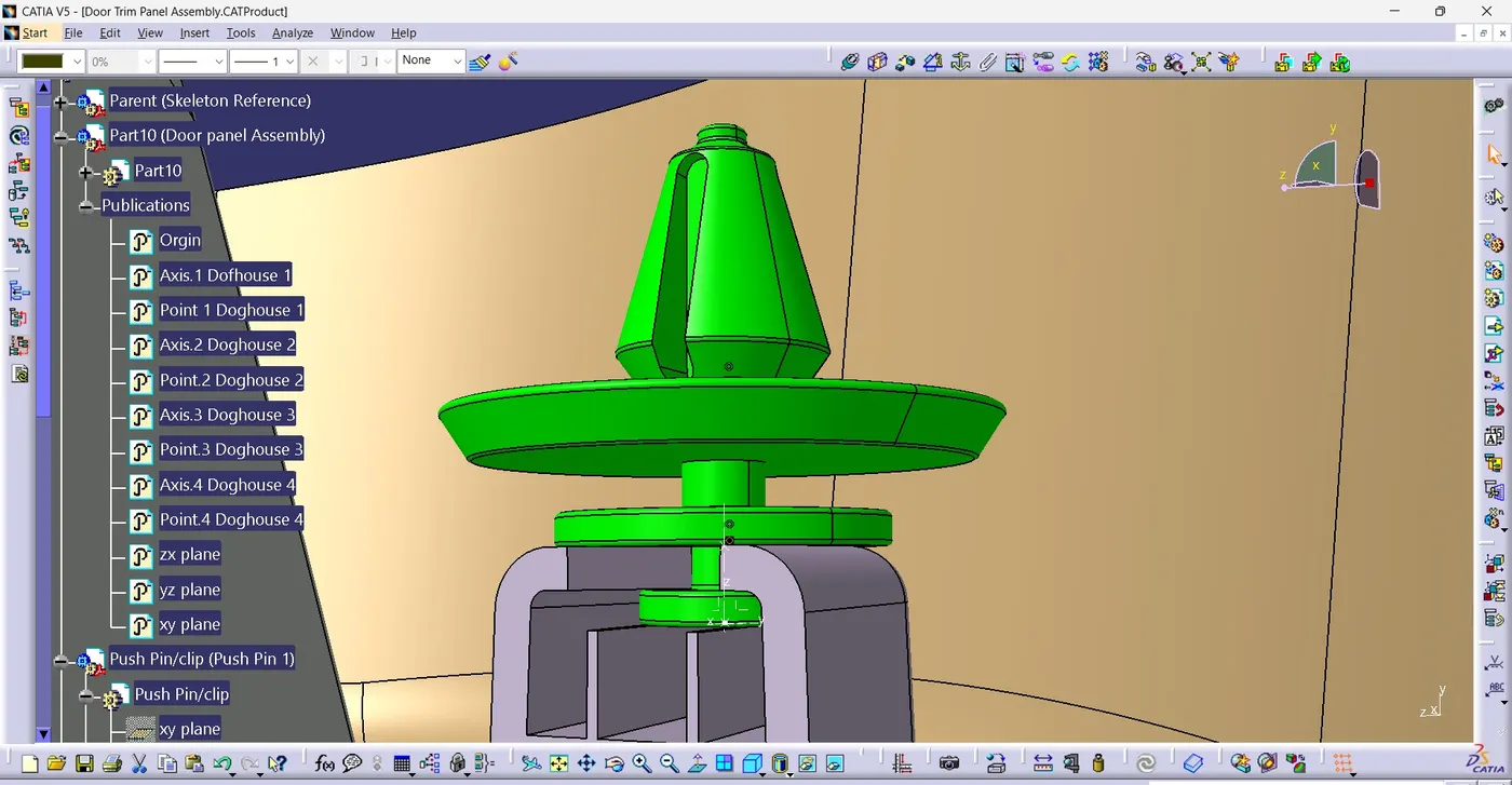
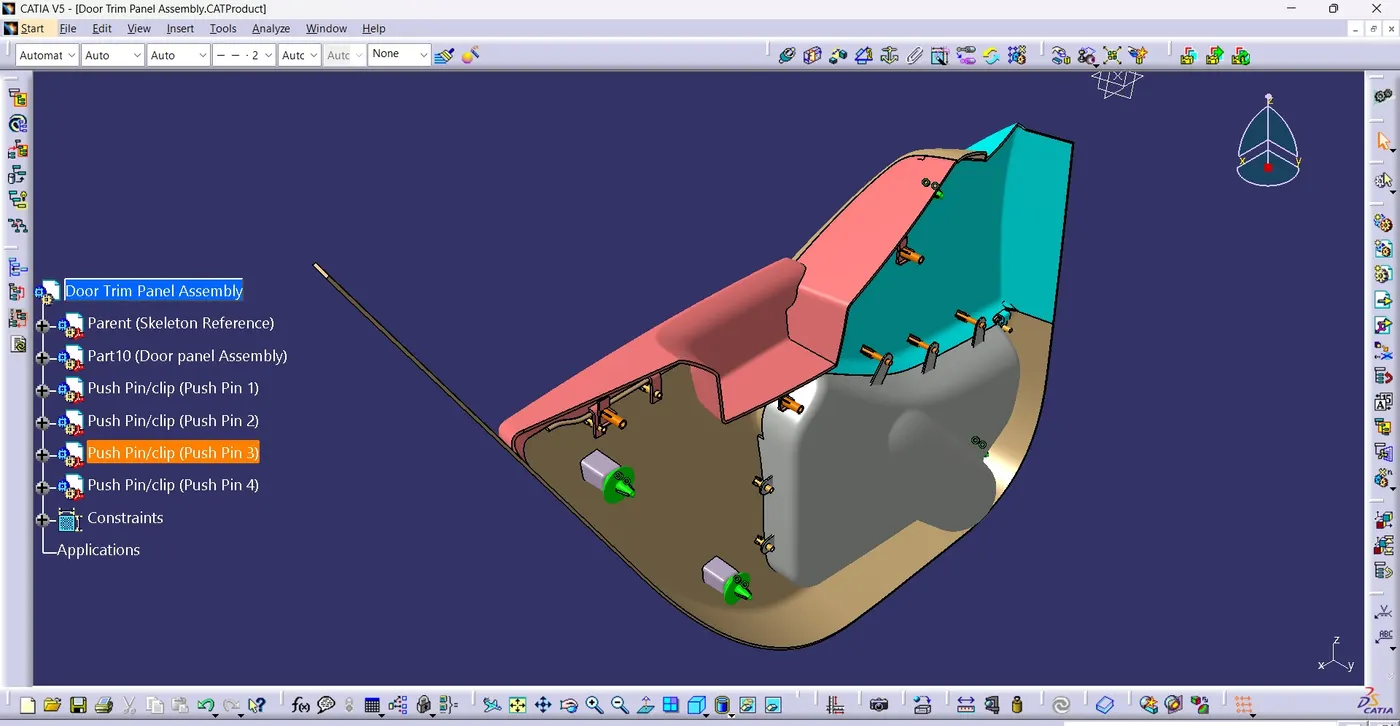
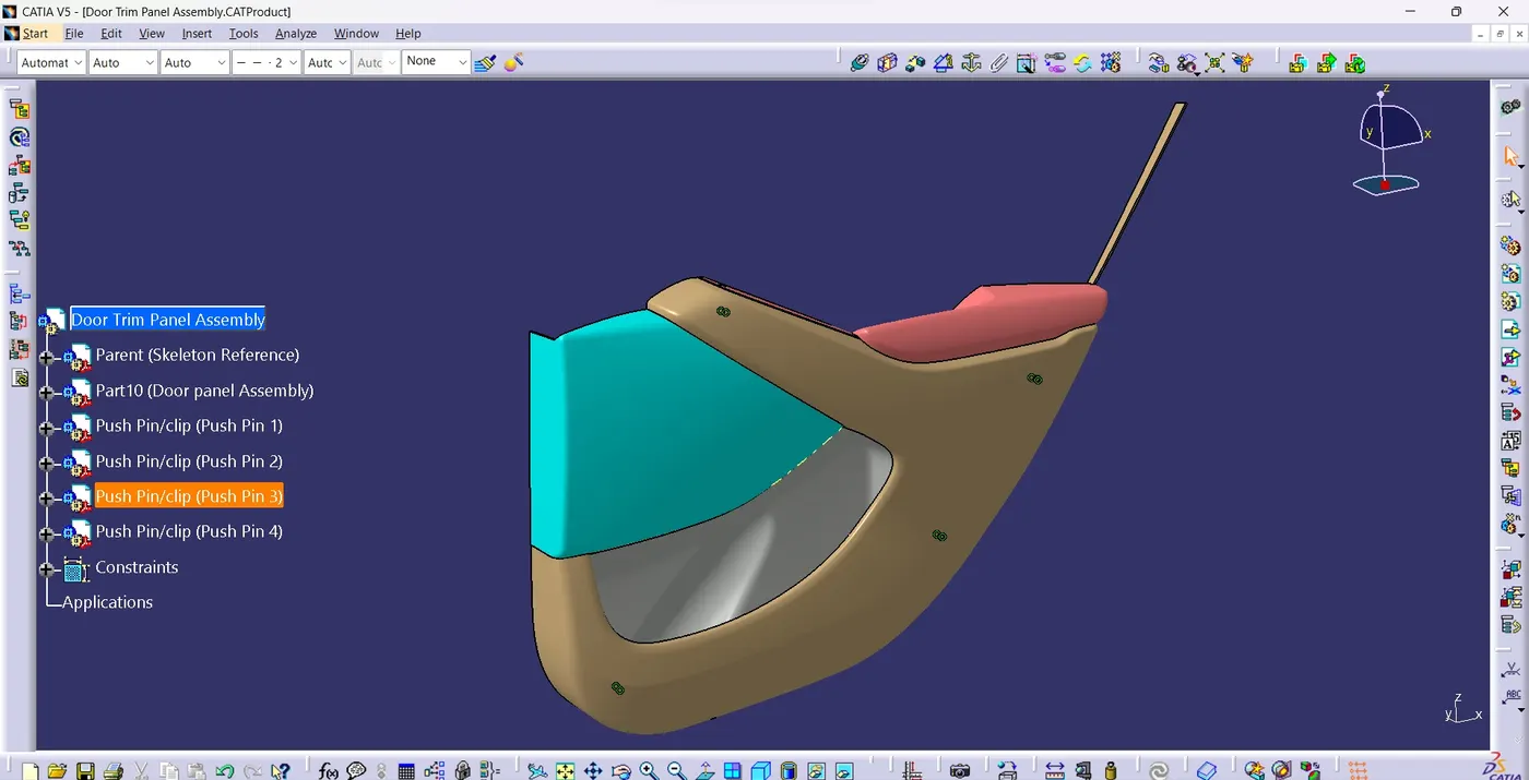
Step 14 : After completing the door panel part Assemble the push pin clip with the dog house to complete the Assembly.
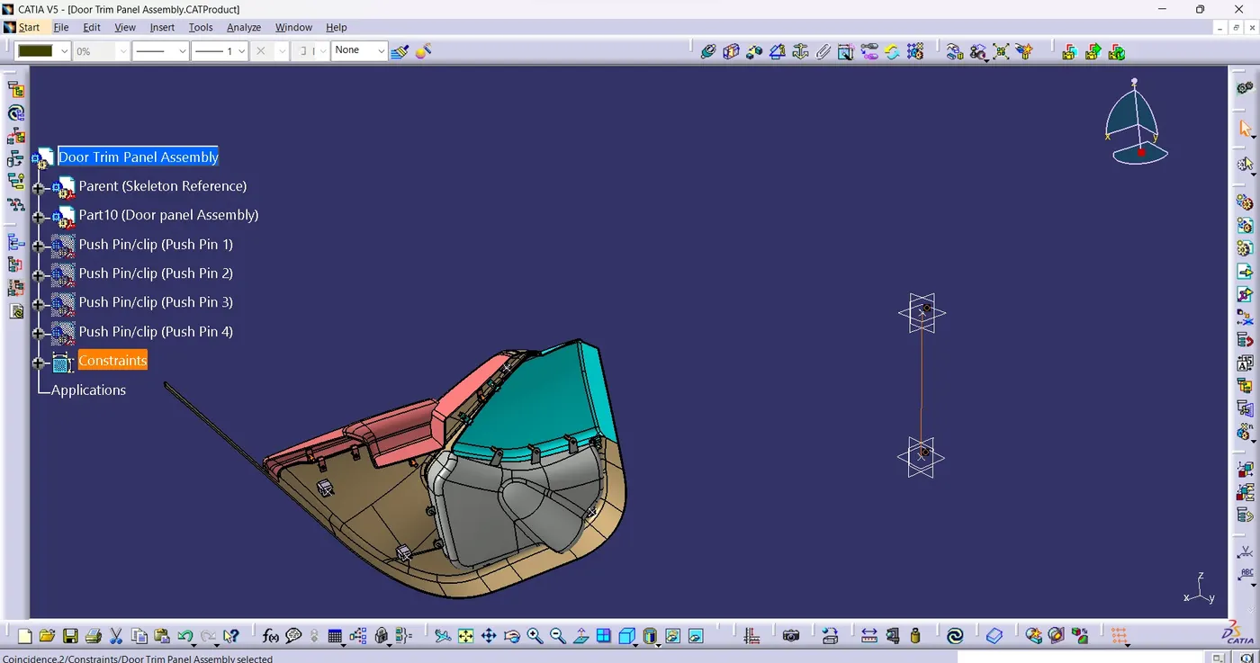
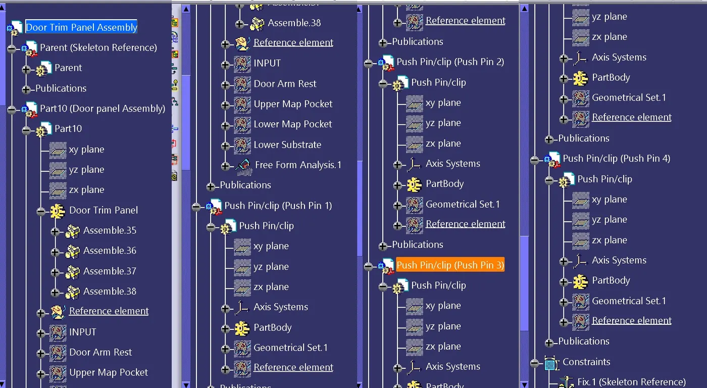
- Open a new product file in assembly workbench.
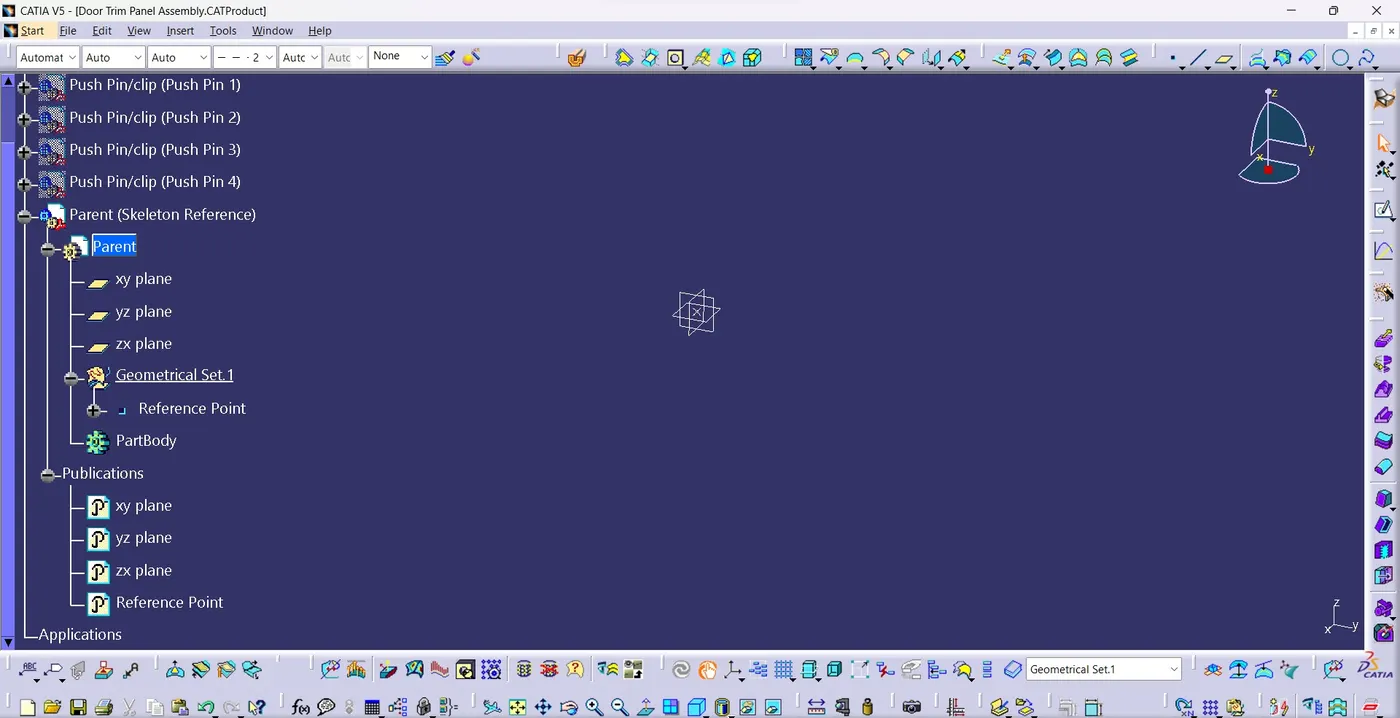
- Add a part with point at orgin,which will be considered as parent of door panel and push pin.
- After adding the part publish the points and planes of the parent part and fix the parent using 'Fix' command.
- Insert the door panel and push clip to the assembly work bench.
- Create reference point and axis on the door panel dog house and publish them.
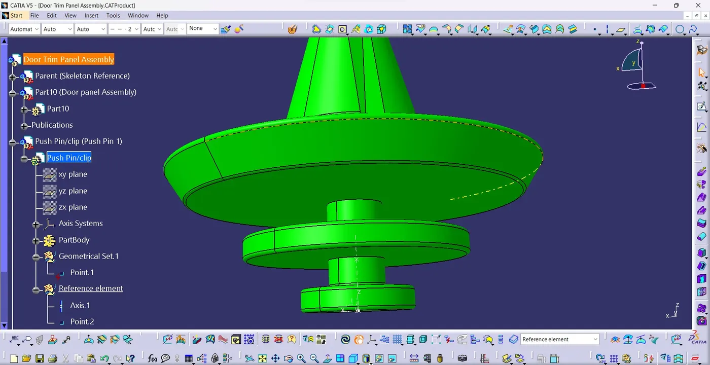
- Similarly do the same for push clip also.
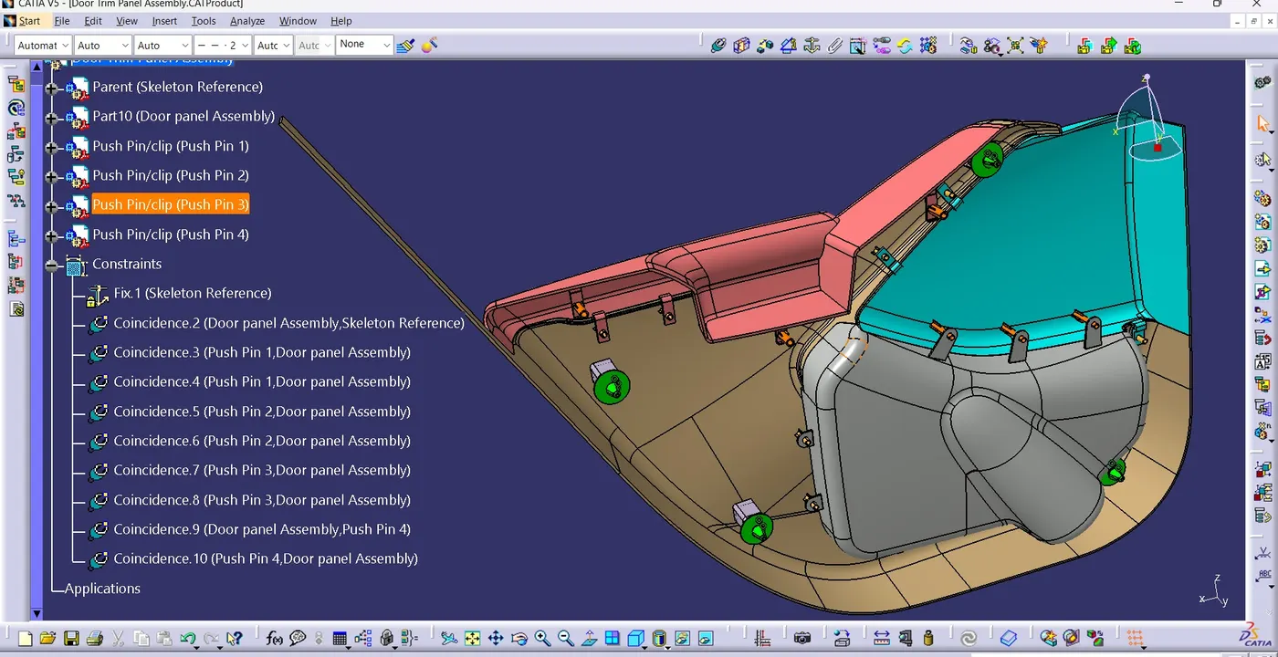
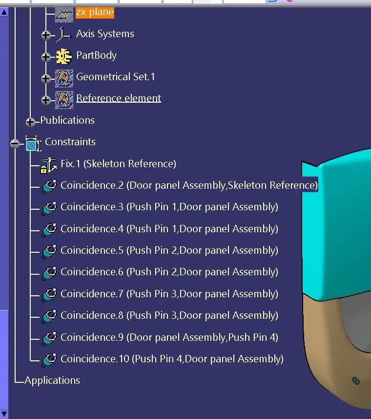
- Using 'Coincide Constrain' by using command allign the parts
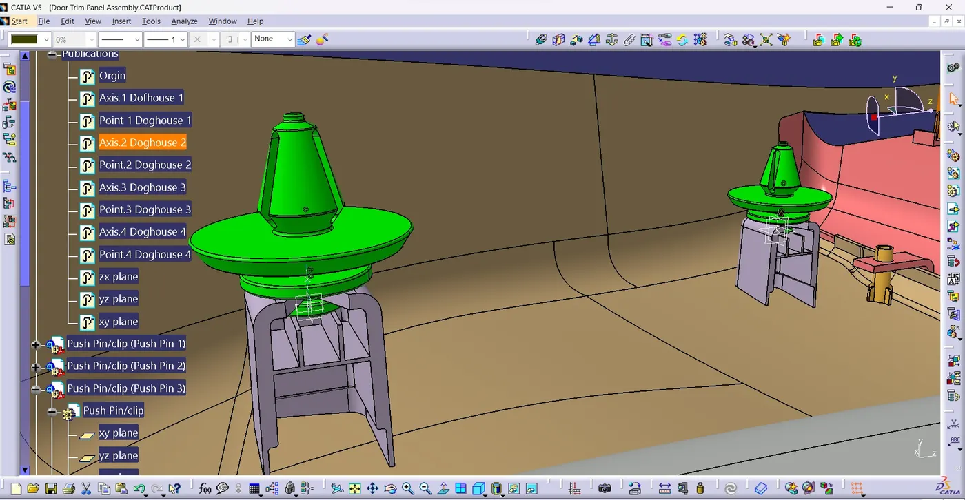
Final Assembly
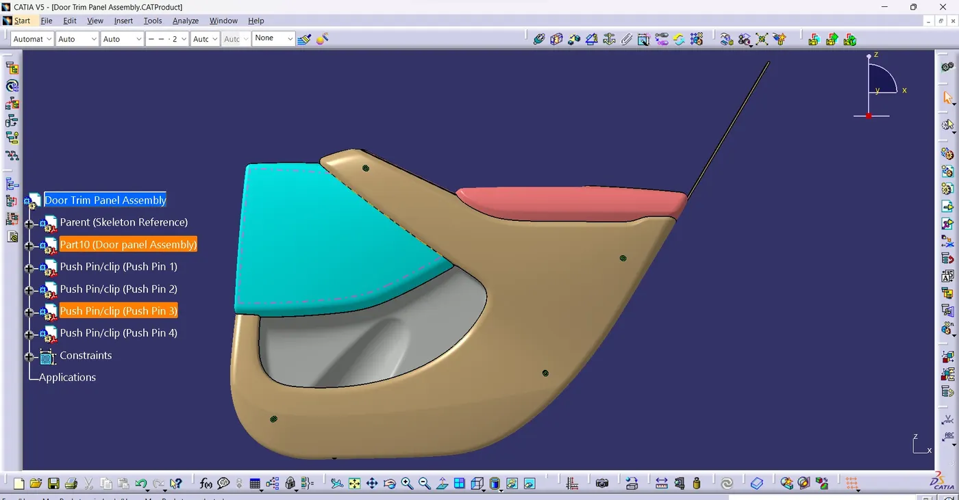
Front View
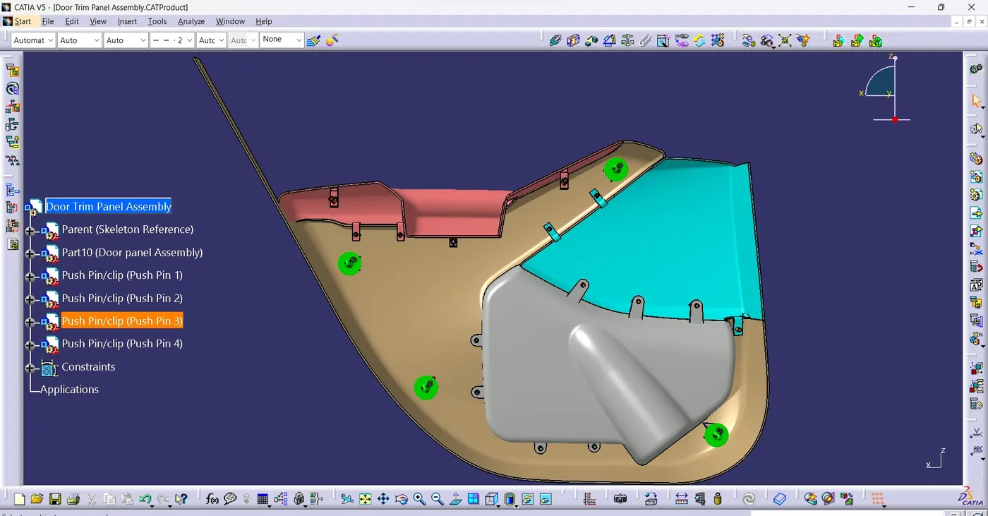
Rear View
Isometric View
Tree Structure
CONCLUSION
A door trim modle was developed from Class A surface, adding the required B side feactures with design parameters in reference from the master section.