Wiring harness design in CATIA V5 - 3D modeling Week 4 Challenge
AIM
To route harness layout in Electrical Workbench
THEORY
Process of wiring harness component definition :
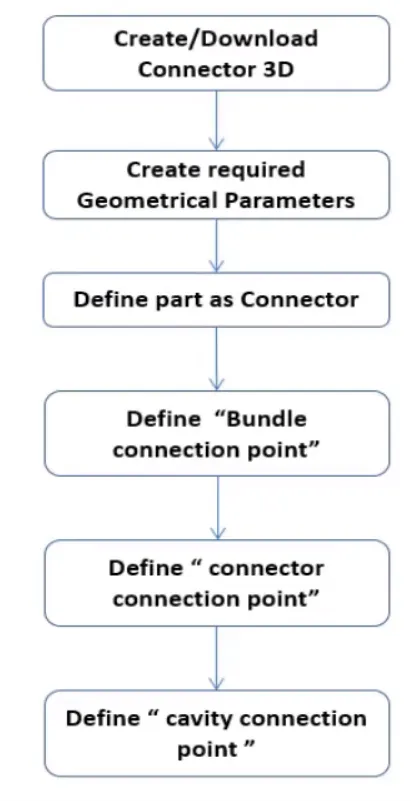
After wiring harness component definition next step is wiring harness assembly.Wiring harness product assembly contains :
- The Harness Contex Assembly :It contains the harness geometrical bundle/Assembly and the wiring harness electrical bundle.
- Geometrical bundle : This file is a sub level file of Harness Contex Assembly and contain all of the harness component.eg: clips, grommets,supports,connectors,splice,annotaitoin and actual physical bundle segments and branches.
- Electrical bundle : This is also a sub file of Harness Contex Assembly and contain all the electrical circuite information.
PROCEDURE
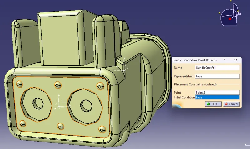
Step 1: All the connectors are converted to Electrical part from Mechanical part and the Connector connection and Bundle connection parametere were defined.
- DT06-08SA is opened as mechanical part and after introducing the axis system for both connector connection point and Bundle connection point
- The workbench is changed to electrical workbench and the mechanical part is defined as electrical connector using 'Define connector' command.
- After converting to electrical part using 'Define Connector connection point' the connection point is defined.
- Then using 'Define bundle connection point' the bundle connection parameters were defined.
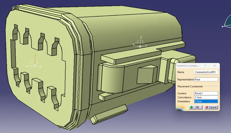
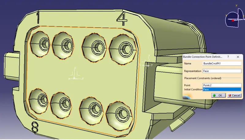
- DT06-6S is opened as mechanical part and after introducing the axis system for both connector connection point and Bundle connection point
- The workbench is changed to electrical workbench and the mechanical part is defined as electrical connector using 'Define connector' command.
- After converting to electrical part using 'Define Connector connection point' the connection point is defined.
- Then using 'Define bundle connection point' the bundle connection parameters were defined.
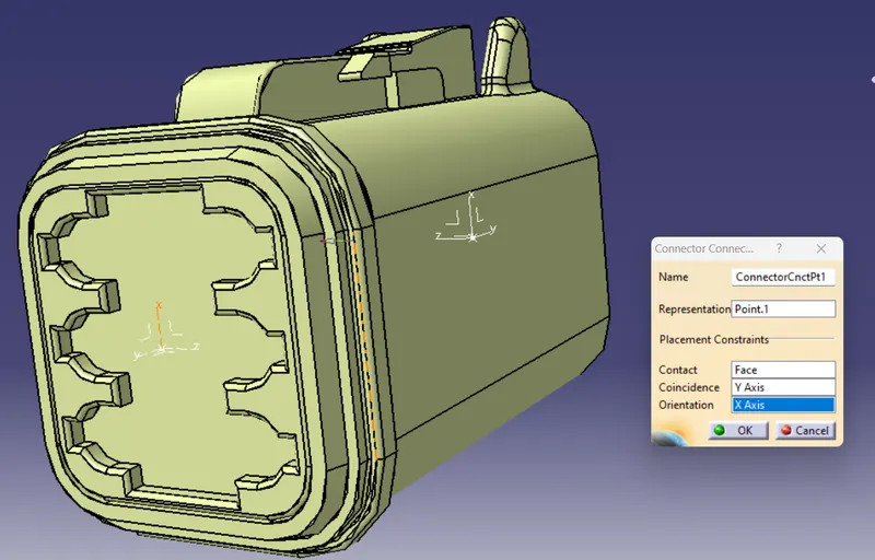
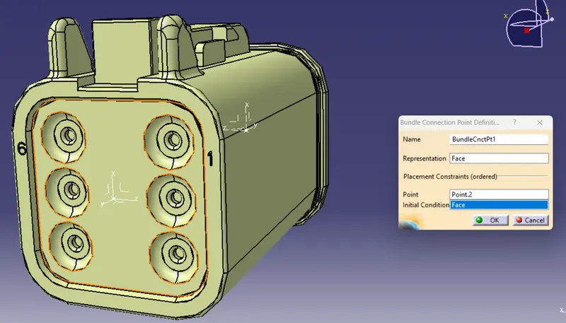
- DT06-4S is opened as mechanical part and after introducing the axis system for both connector connection point and Bundle connection point
- The workbench is changed to electrical workbench and the mechanical part is defined as electrical connector using 'Define connector' command.
- After converting to electrical part using 'Define Connector connection point' the connection point is defined.
- Then using 'Define bundle connection point' the bundle connection parameters were defined.
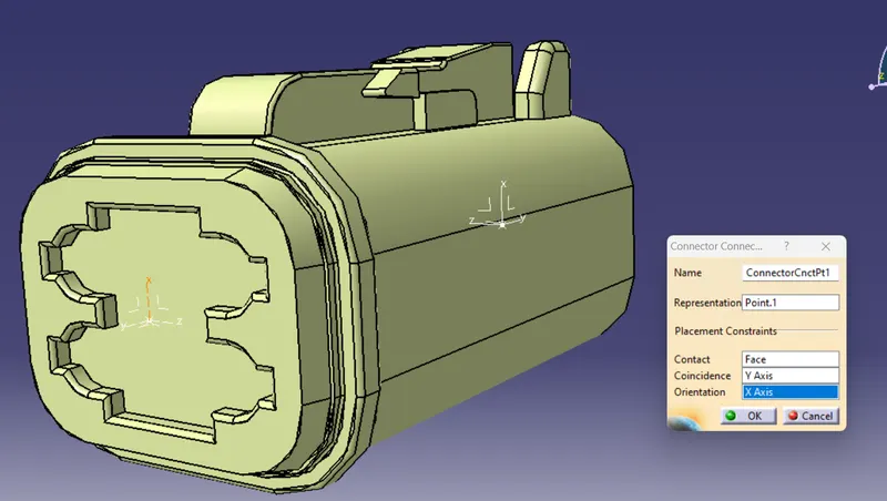
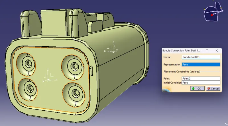
- DT06-2S is opened as mechanical part and after introducing the axis system for both connector connection point and Bundle connection point
- The workbench is changed to electrical workbench and the mechanical part is defined as electrical connector using 'Define connector' command.
- After converting to electrical part using 'Define Connector connection point' the connection point is defined.
- Then using 'Define bundle connection point' the bundle connection parameters were defined.
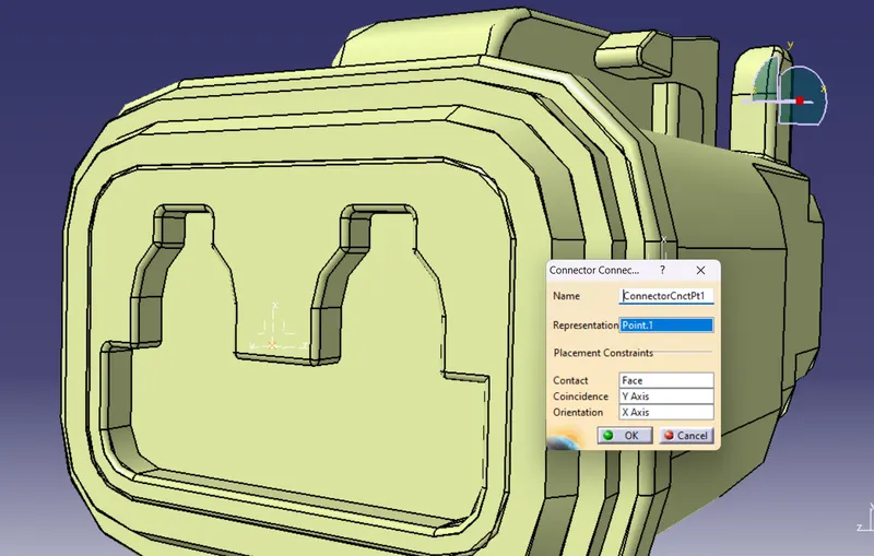
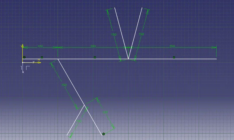
Step 2 : After defining all the connectors with required parameters the path for the wiring harness in space is created using Sketch command
Step 3 : Open a new product file then rignt click on tree and goto components and new product which will create a new product , rename it as Geometrical bundle.
Step 4 : Insert the path file created into the geometrical bundle file by opening it in new window using 'existing product' command.
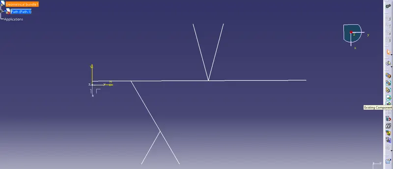
Step 5: Import all the connectors needed into the geometric bundle file using 'existing component' command.
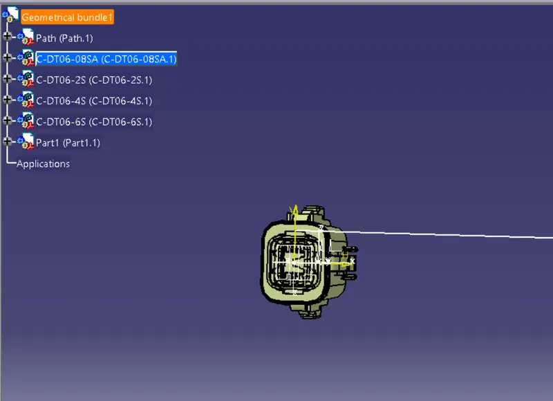
Step 6 : Convert Mechanical assembly file to Electrical bundle assembly file.
- Switch to 'Electrical Harness Assembly'.
- Select 'Geometrical bundle command' and click on the file name 'Geometrical bundle' to convert to Electrical bundle assembly file.

Step 7: Use Manipulate and snap command to arrange the connectors in positon.
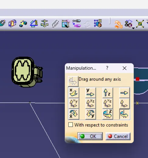
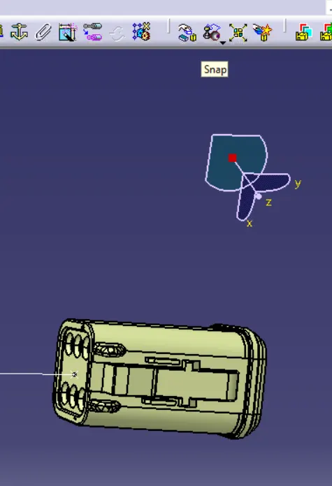
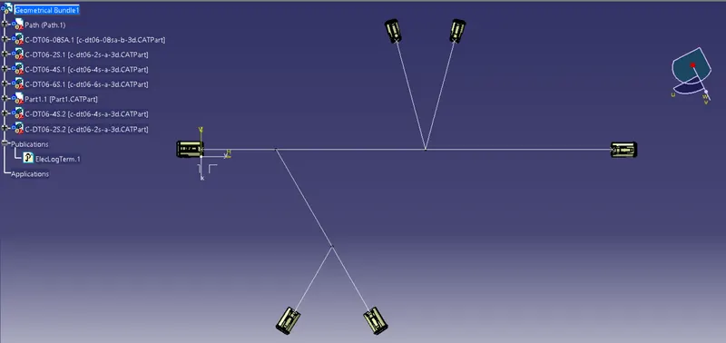
Step 8 : After arranging all the connectors in position now we have to switch to 'Electrical harness installiation' workbench to make the wiring.
Step 9 : Select the Branch definition command and the following dilogue box pop up.
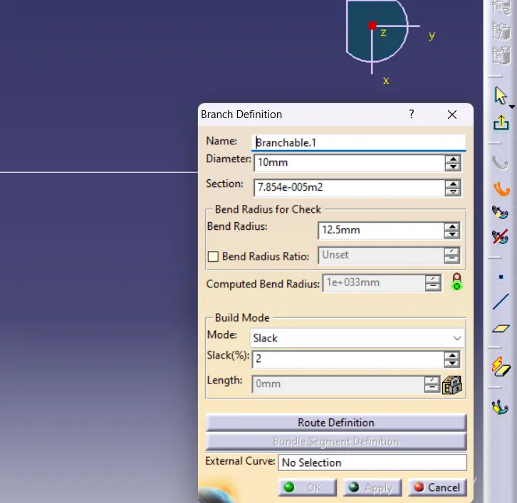
The Slack % is changed to Zero and the Bend radius checkbox is checked and given 1.4 as its value all other values are kept same.
Step 10 : After giving the details click on the Route Definition to select components for wiring harness routing.
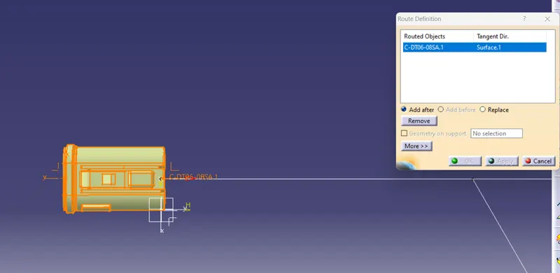
Once the first component is selected check the direction of the wiring shown and select the next component.
Step 11 : Once the main wiring harness is made we need to make the branchs to each connectors from the main branch. For that we need to split the main wiring harness at the required branch point using 'Add branch point' command.
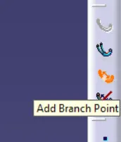
Step 12 : Once the command selected click on the main wiring harness and given the value or click on the required position.
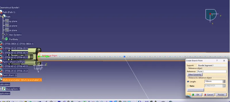
Step 13 : Now as before select the 'Branch definition' command select route definition.Then select wiring porition form where the branch has to start.Repeat the steps for making other branches.
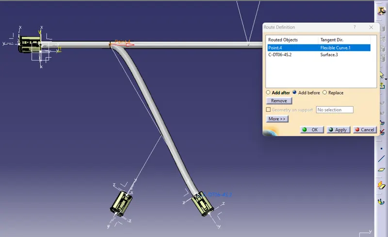
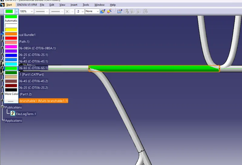
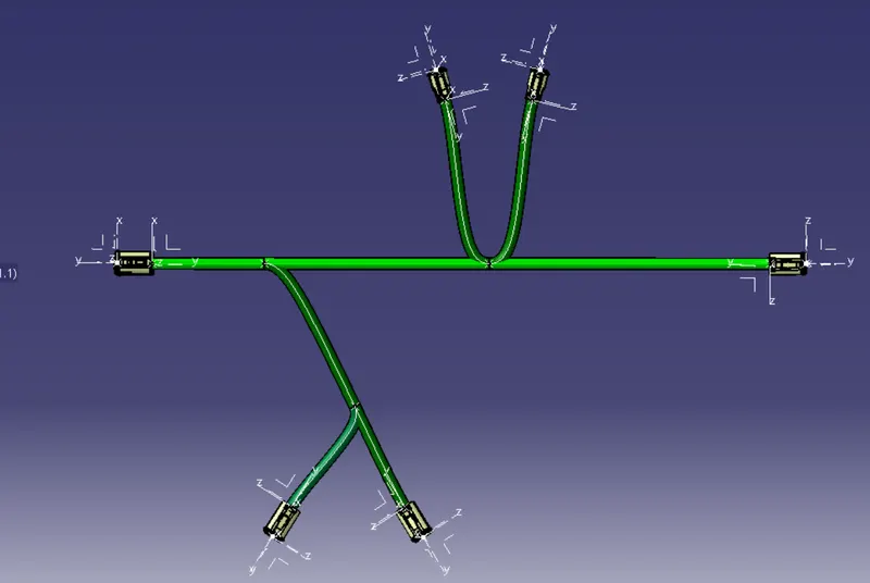
Step 14 : We can change color of the harness for better visualization.
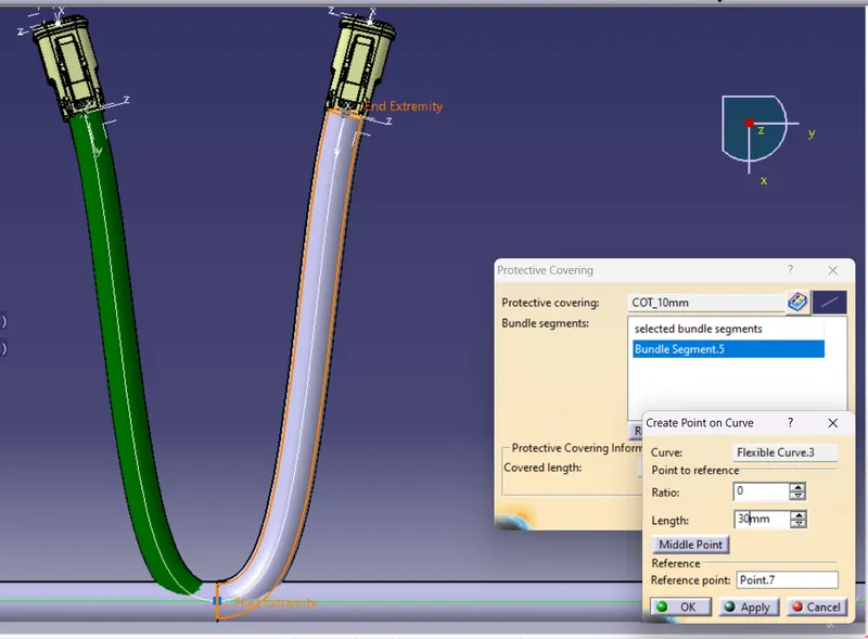
Step 14 : Inserting protective covering.
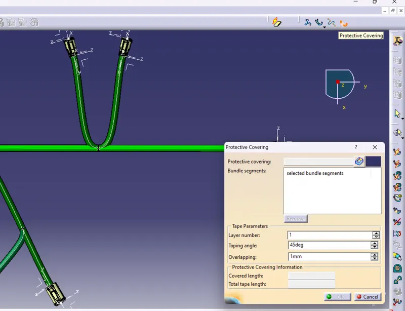
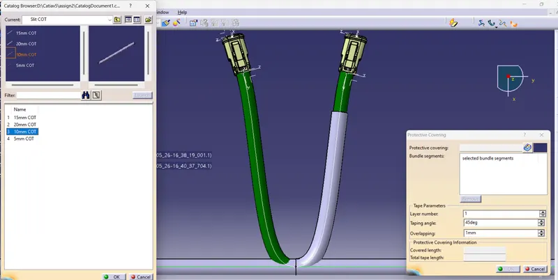
- Select the protective covering command and open the catalogue and select the corrugated tube from the catalogue which was stored.
- Click on the wiring harness and adjust the extrimity.
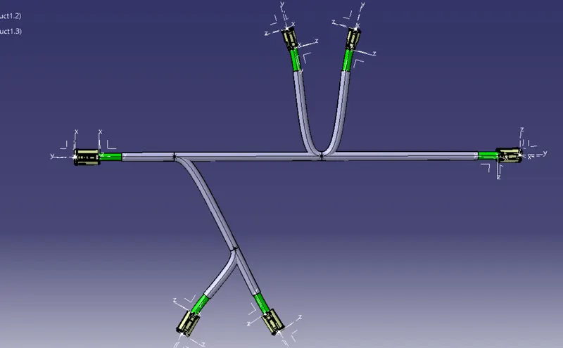
RESULT
Wiring harness routing has done for the given layout.