Wiring harness design in CATIA V5 - 3D modeling Week 2 Challenge
AIM
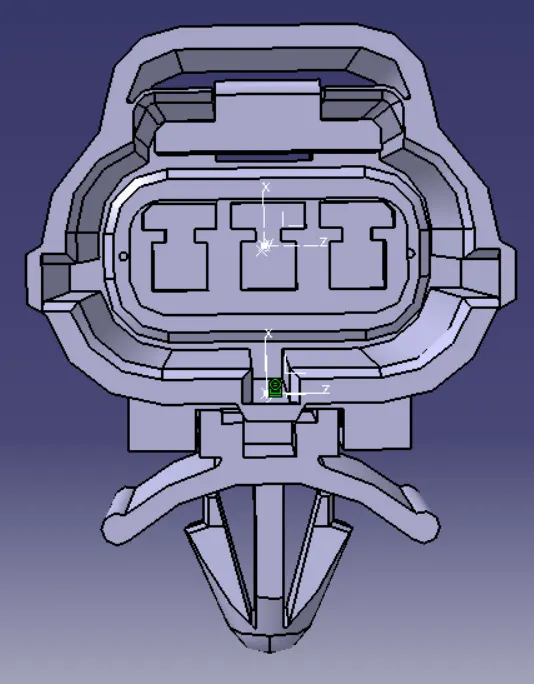
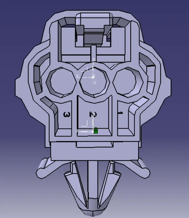
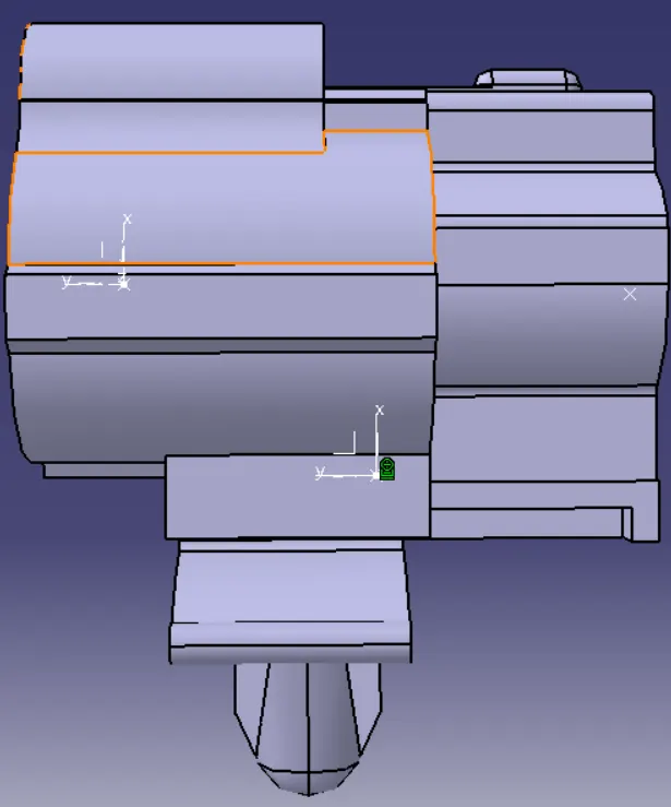
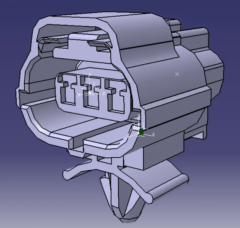
To define connectors & connector clip as Electrical Connector using Electrical Part design Workbench.
THEORY
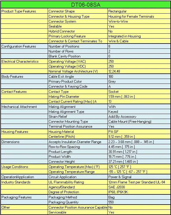
DT06-08SA
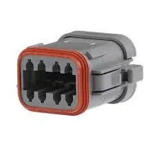
The DT06-08SA connector is a rectangular connector manufactured by Deutsch. It is commonly used in automotive and industrial applications for connecting electrical components and wires.
The DT06-08SA connector features a rectangular design with a locking system that ensures a secure and reliable connection. It has eight pins, allowing for multiple electrical connections to be made between devices or components.
The connector is made from high-quality materials that provide excellent resistance to corrosion, chemicals, and extreme temperatures. The housing of the connector is made from thermoplastic material, which offers good durability and impact resistance.
The DT06-08SA connector has a current rating of 13A and a voltage rating of 250V AC/DC. It is designed to withstand harsh environments and is IP67 rated, which means it is protected against dust and water ingress.
This connector is also compatible with a range of Deutsch contacts, which are available in different sizes and configurations to suit specific wiring requirements. The contacts can be easily inserted and removed from the connector using a special tool, allowing for easy maintenance and repair.
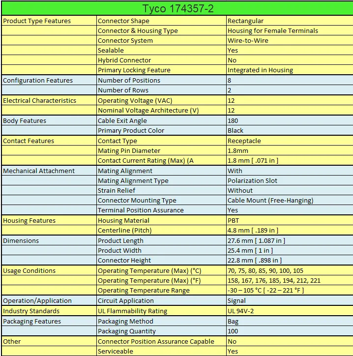
Tyco 174357-2
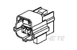
The Tyco 174357-2 connector is a type of wire-to-board connector manufactured by TE Connectivity. It is commonly used in a wide range of electrical and electronic devices for connecting wires to a printed circuit board (PCB).
The 174357-2 connector is a two-position connector, meaning that it has two contacts or terminals for electrical connections. It is designed to be used with wires that are between 16-22 AWG in size, which makes it suitable for a wide range of applications.
The connector features a compact and low-profile design, which makes it ideal for use in space-constrained applications. It is made from high-quality materials that provide excellent durability and resistance to harsh environments. The connector housing is made of a UL94V-0 rated thermoplastic material, which provides good mechanical strength and resistance to heat and chemicals.
The Tyco 174357-2 connector also features a positive locking mechanism that ensures a secure and reliable connection. This mechanism helps prevent accidental disconnection of the wires from the connector, which is particularly important in applications where the device may be subjected to vibration or shock.
The connector is rated for a maximum current of 7.5A and a maximum voltage of 250V AC/DC. It has a temperature rating of -40°C to +105°C, making it suitable for use in a wide range of environments.
The Tyco 174357-2 connector is widely used in various industries, including automotive, aerospace, telecommunications, and consumer electronics. It is a popular choice for applications that require a reliable and secure wire-to-board connection in a compact and low-profile package.
Tyco 85229-1
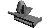
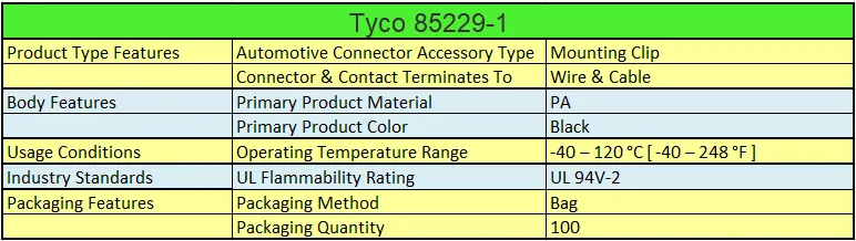
The Tyco 85229-1 Automotive Connector Accessory Clip is a component used in automotive wire harness assemblies with a Tyco 85229-1 connector.
This accessory clip is designed to attach to the Tyco 85229-1 connector, which is a wire-to-board connector commonly used in automotive applications to connect wires to a printed circuit board. The accessory clip provides additional support and strain relief to the wires connected to the connector, helping to prevent them from becoming loose or disconnected due to vibration or other mechanical stresses.
The Tyco 85229-1 Automotive Connector Accessory Clip is made from high-quality materials that provide excellent durability and resistance to harsh automotive environments. It is designed to be easily installed and removed from the connector, allowing for easy maintenance and repair.
This accessory clip is a reliable and cost-effective solution for securing wire-to-board connectors in automotive wire harness assemblies. It is widely used in various automotive applications, including engine control modules, body control modules, and other electronic control units.
PROCEDURE
1. Defining Deutsch DT06 – 08SA as Electrical Connector
Step 1 : Open the downloaded connector in catia v5
Step 2 : Define orgine in the connector mating face and name as 'Connector Connection point'.
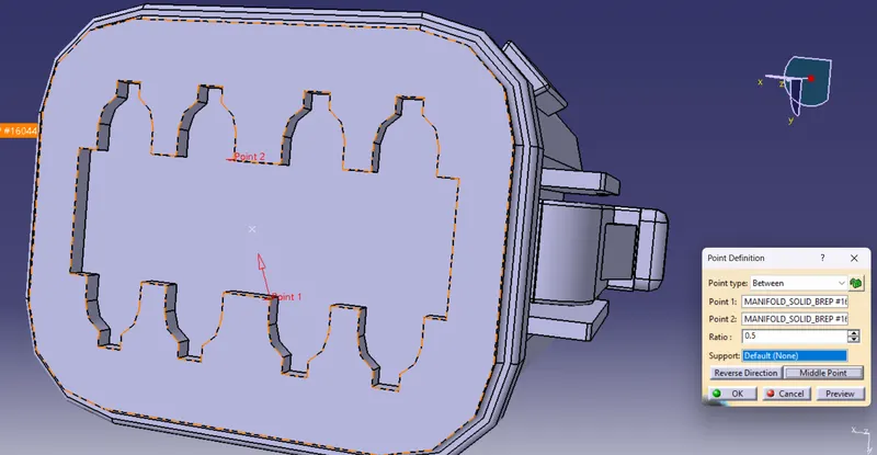
Step 3 : Create the axis system in the connector mating face.
Orgine : The point created in the connector mating face.
X axis : Should be kept towards locking direction
Y axis : In the direction of mating face
Z axis : Towards top
Rotate each axis and make the axis as required.
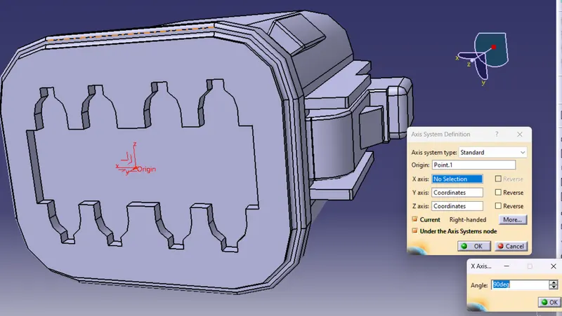
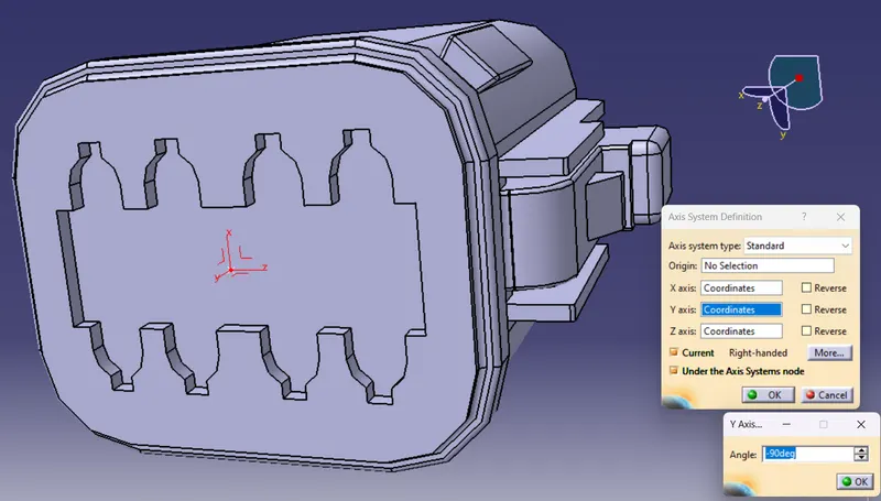
Step 4 : Goto axis system right click and select axes properties in the tree and rename it as connector cavity axis in the feature properties.
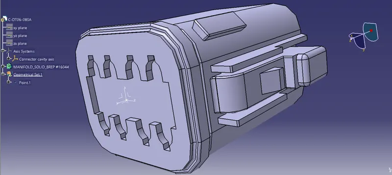
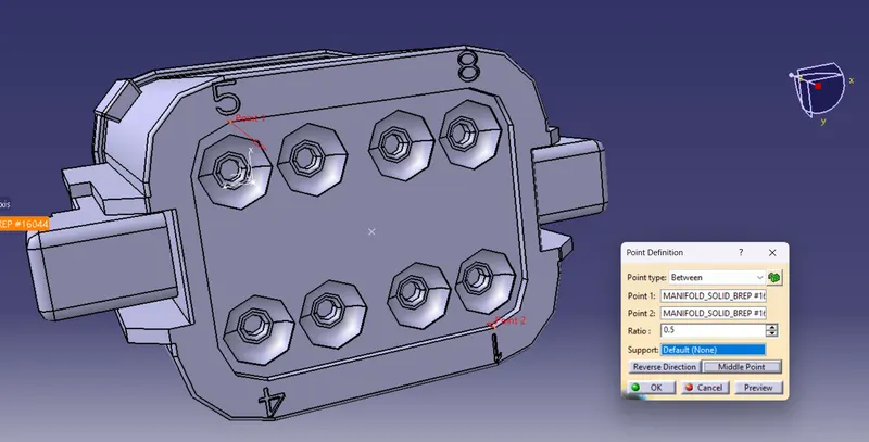
Step 5 : Create entry connection point in the bundle entry side and rename as 'Bundle Entry Point'
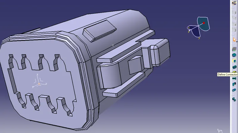
Step 6 : Switch to Electrical Part Design workbench and Define the part as Electrical Connector
- After switching to Electrical Part Design workbench, to define the part as electrical connector goto Define Connector in the command window.
- Once the Define connector is selected select the model of the connector, the geometry of connector will get highlighted.
- Now in the dilogue box popped up we have to give type of connector, here 'Single insert connecotr' and no of wires that will be entering the connector, here it is 8
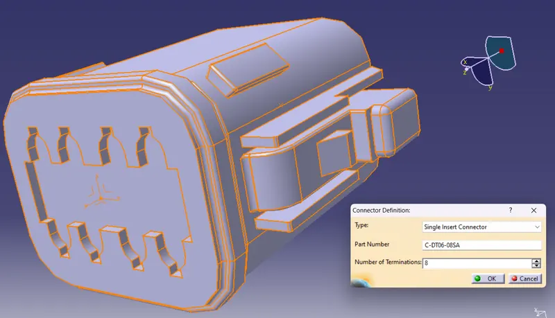
Step 7 : Define Bundle Connection point.
Define bundle connection point command is selected from the command window and select the connector model.
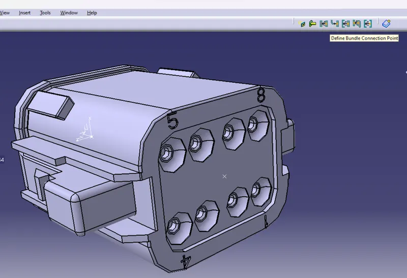
The selection won't happen if the model is not defined as 'Electrical Connector'.
Now a dilogue box popes up and the following details need to be given.
Representation : Is always surface normal to bundle entry point ie. the entry face of connector.
Point : Bundle entry point that was defined before.
Initial Condition : The direction to which the bundle entry if normal.It will be same face selected for representation.
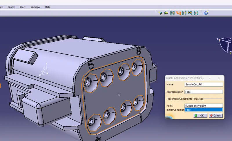
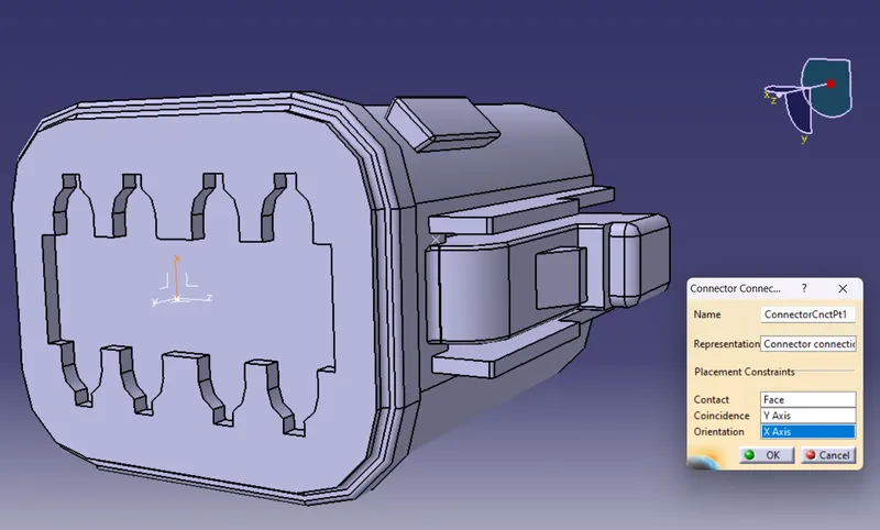
Step 8 : Defining Connector connecting point.
Select the connector conection point from the workbench and select the connector model.
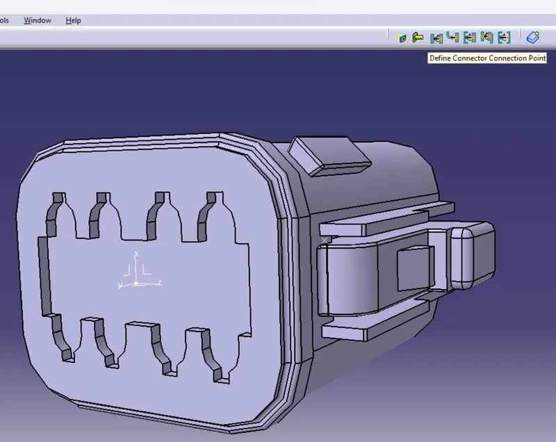
Now a dilogue box popes up and the following details need to be given.
Representation : Select the 'Connector connection point' which was defined before.
Contact : It is the front face or the last face of the connector.
Coincidence : Y - axis.
Orientation : X - axis.
2. Defining Tyco 174357-2 as Electrical Connector
Step 1 : Open the downloaded connector in catia v5.
Step 2 : Define orgine in the connector mating face and name as 'Connector Connection point'.
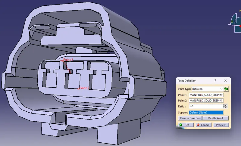
Step 3 : Create the axis system in the connector mating face.
Orgine : The point created in the connector mating face.
X axis : Should be kept towards locking direction
Y axis : In the direction of mating face
Z axis : Towards top
Rotate each axis and make the axis as required.
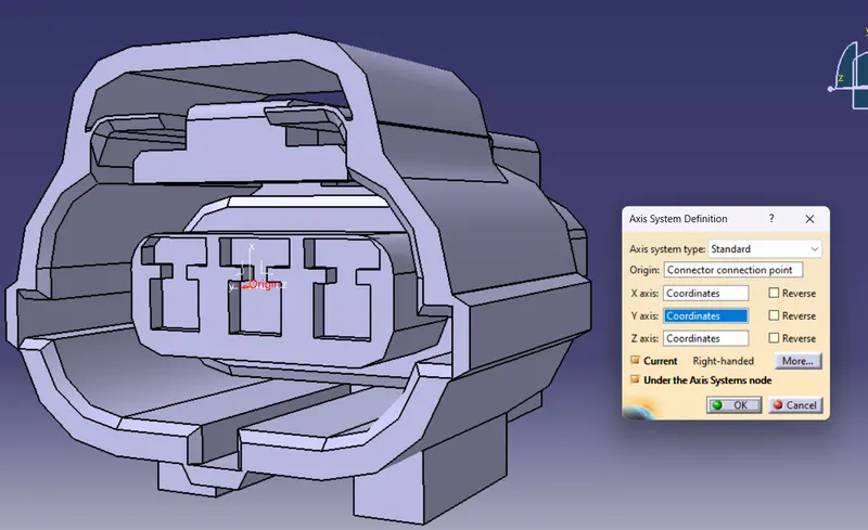
Step 4 : Goto axis system in the tree and rename it as connector connecting axis.
Step 5 : Create entry connection point in the bundle entry side and renamee as 'Bundle Entry Point'.
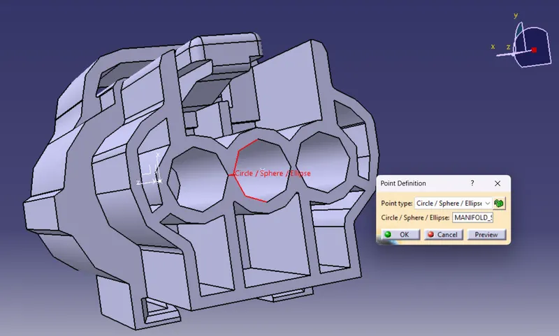
Step 6 : Switch to Electrical Part Design workbench and Define the part as Electrical Connector.
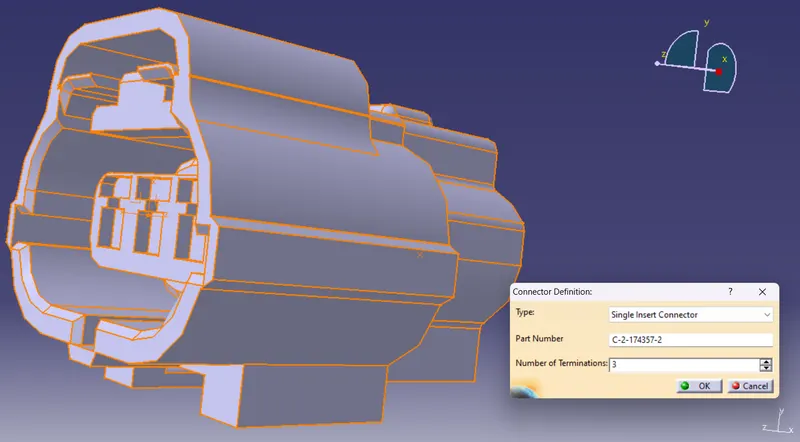
- After switching to Electrical Part Design workbench, to define the part as electrical connector goto Define Connector in the command window.
- Once the Define connector is selected select the model of the connector, the geometry of connector will get highlighted.
- Now in the dilogue box popped up we have to give type of connector, here 'Single insert connecotr' and no of wires that will be entering the connector, here it is 8
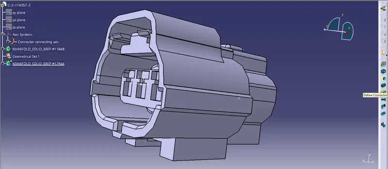
Step 7 : Define Bundle Connection point.
Define bundle connection point command is selected from the command window and select the connector model.
The selection won't happen if the model is not defined as 'Electrical Connector'.
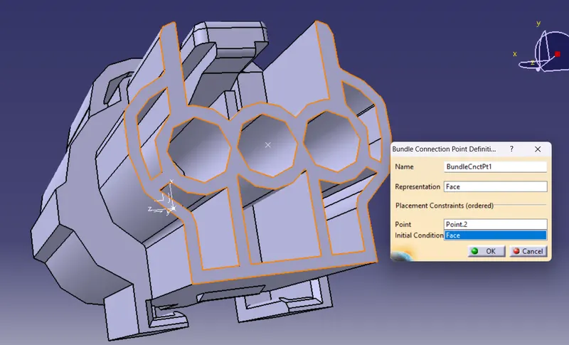
Now a dilogue box popes up and the following details need to be given.
Representation : Is always surface normal to bundle entry point ie. the entry face of connector.
Point : Bundle entry point that was defined before.
Initial Condition : The direction to which the bundle entry if normal.It will be same face selected for representation.
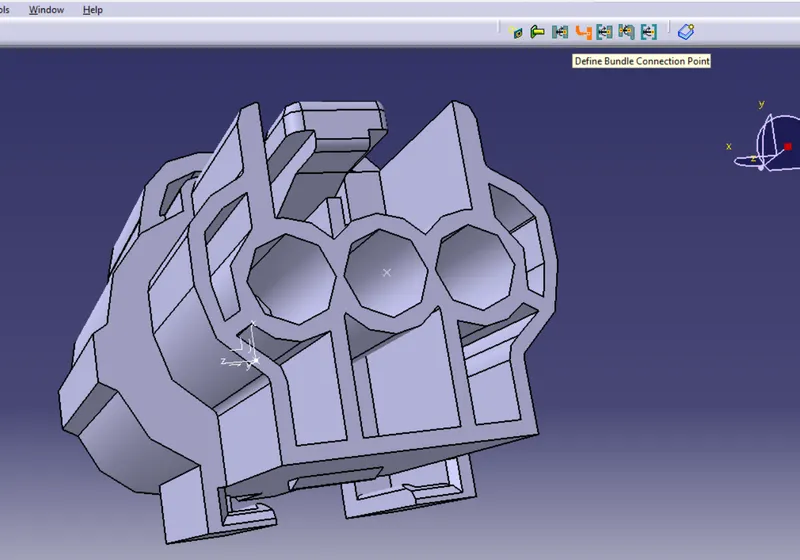
Step 8 : Defining Connector connecting point.
Select the connector conection point from the workbench and select the connector model.
Now a dilogue box popes up and the following details need to be given.
Representation : Select the 'Connector connection point' which was defined before.
Contact : It is the front face or the last face of the connector.
Coincidence : Y - axis.
Orientation : X - axis.
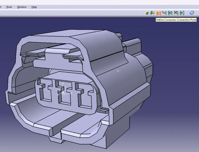
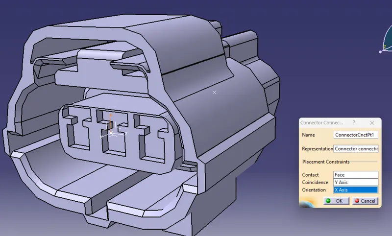
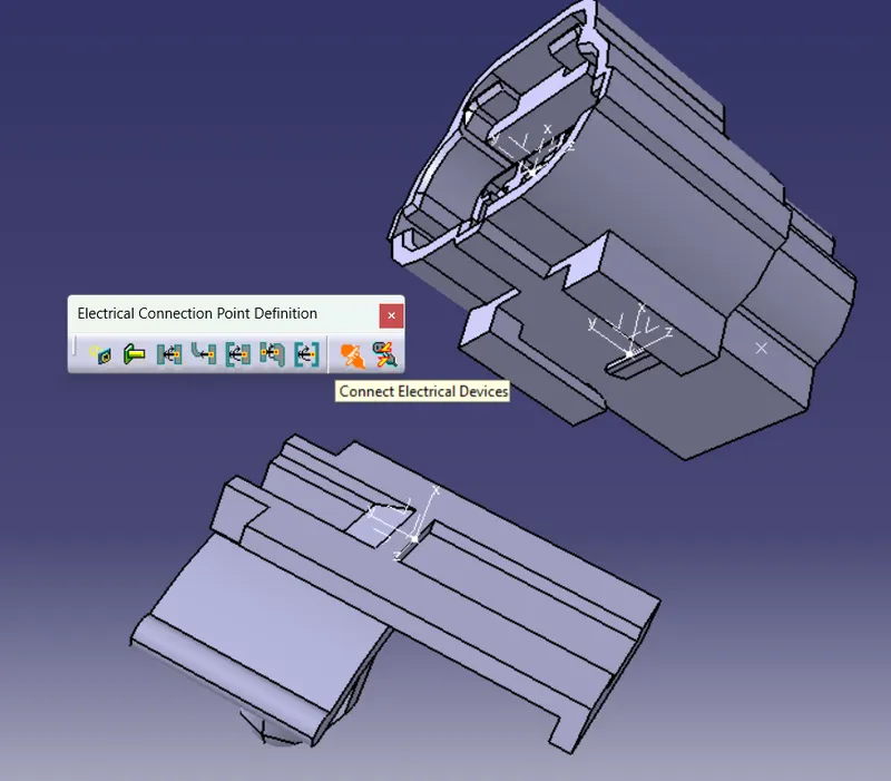
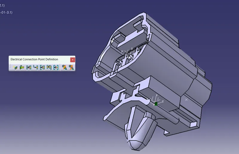
Step 9 : Defining Cavity Connection Point.
This is done only for the connectors that have connector locking feature which means the provision to accomodate connector mounting clip.
The connector mounting clip should be fixed with the connector housing to mount the connector firmly.
There will be locking grip mounted in the model this grip is used to define the cavity connection points.
Change the workbench to mechanical part design.
Create a point on the edge at center of locking grip and define the axis system like done before.
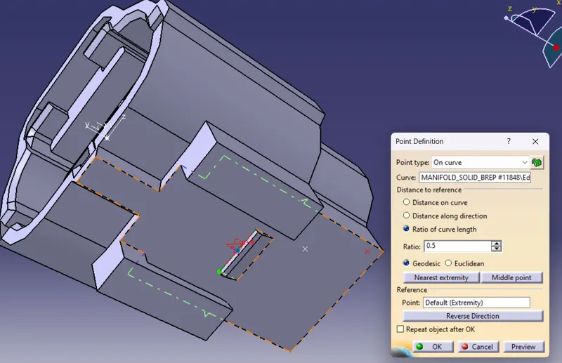
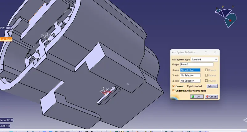
Step 10 : Change to Electrical Part Design workbench and Select the 'Cavity Connection Point' and click on the connector body.
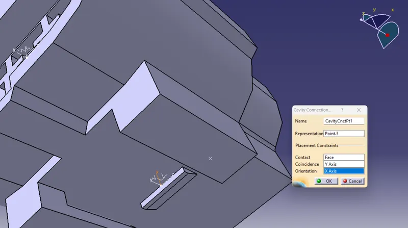
Now a dilogue box popes up and the following details need to be given.
Representation : Select the 'Cavity connection point' which was defined before.
Contact : It is the face mating with the locking grip.
Coincidence : Y - axis.
Orientation : X - axis. 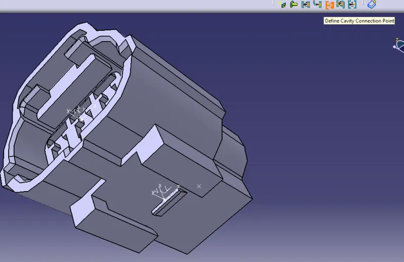
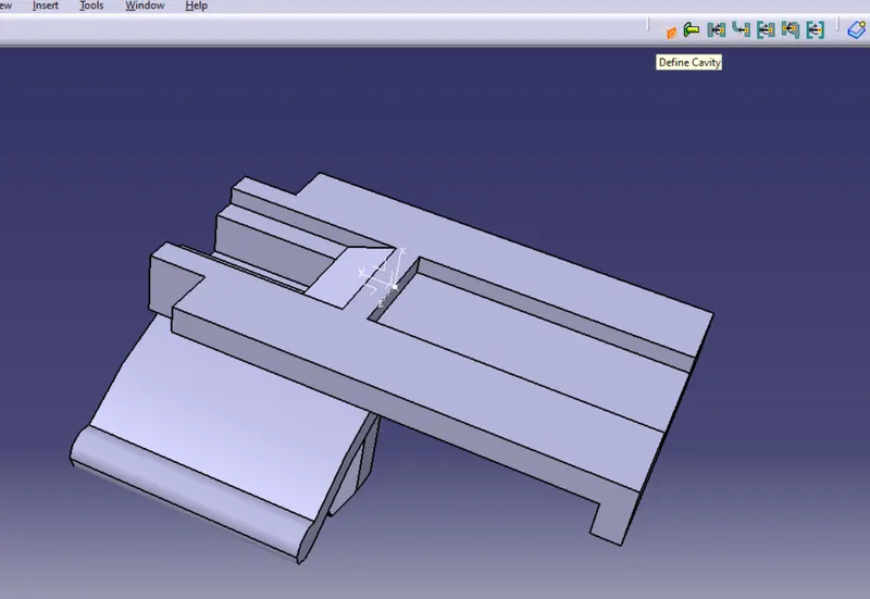
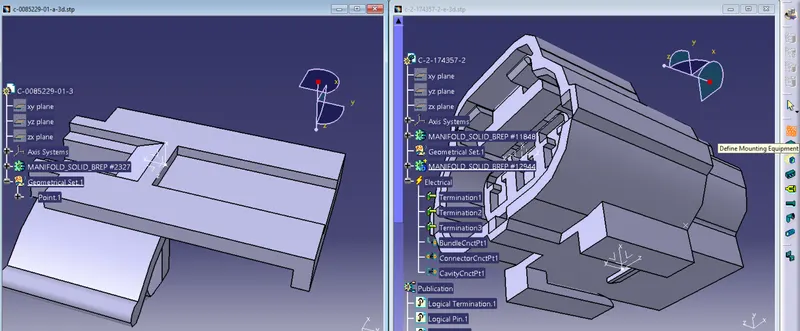
3. Defining Tyco 85229-1 as Electrical Connector Clip
Step 1 : Open the downloaded connector clip in catia v5
Step 2 : Create a point at the center of the mating edge.
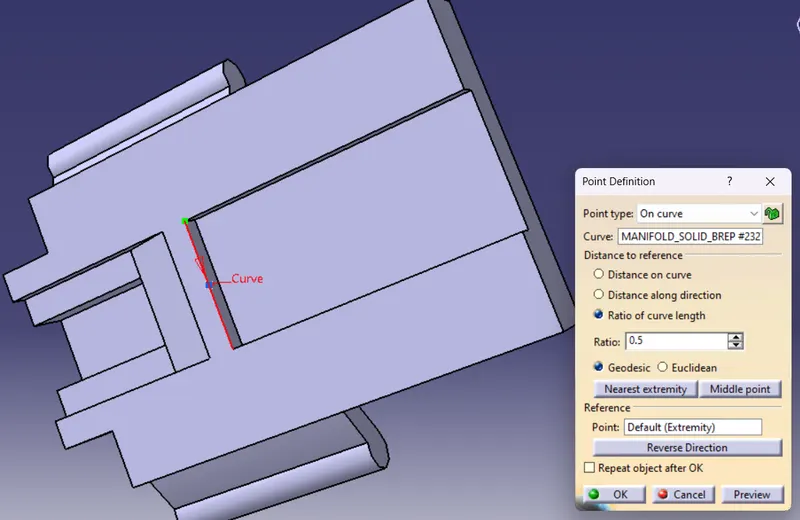
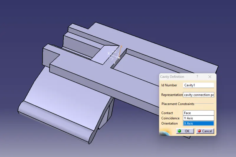
Step 3 : Create an axis system with same orientation created in the connector cavity point.
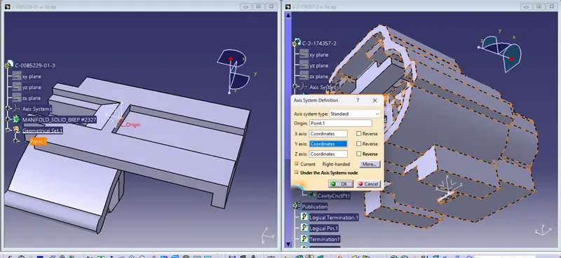
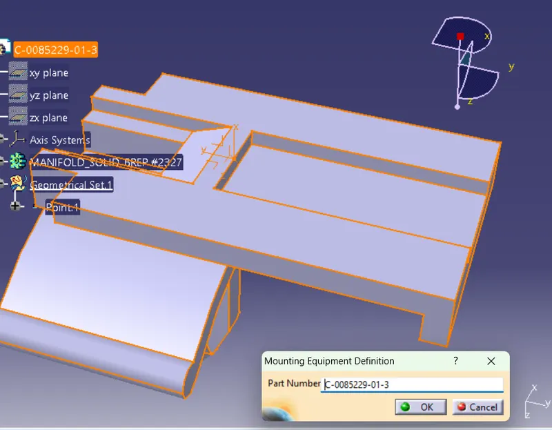
Representation : Select the point which was defined before.
Contact : It is the face that is going to mate.
Coincidence : Y - axis.
Orientation : X - axis.