Week 11 - Project - A pillar Design with Master Section
AIM
To create a pillar design with master section given as the intersection sketch with class A Surface and create the tooling axis and perform the draft analysis.
THEORY
Tooling axis
The tooling axis in plastic injection molding refers to the direction in which the two halves of the mold, the core and cavity, separate or come together during the molding process. It is a critical consideration in design because it influences the part's ease of ejection from the mold, the overall mold complexity, and the final part quality. Properly selecting the tooling axis ensures that the part can be efficiently molded, released from the mold without damage, and meets design specifications. The choice of tooling axis depends on factors like part geometry, draft angles, undercuts, and the desired surface finish, with careful attention needed to optimize the injection molding process.
Draft analysis
Draft analysis is the process of evaluating and measuring the angles or slopes incorporated into the surfaces of a 3D model or physical part. These angles are called "draft angles" or simply "drafts." Draft angles are designed to facilitate the easy removal of a part from a mold or die during manufacturing processes like injection molding or casting.t helps prevent issues like part sticking to the mold, surface defects, or increased production costs.
Class A surface
A Class A surface in simple terms is a very smooth and flawless surface on a product, often seen on things like cars or consumer electronics. It's like the shiny, polished exterior of a high-quality sports car, without any visible imperfections, bumps, or roughness. Designers and manufacturers work hard to create Class A surfaces because they give a product an attractive and premium look, making it more appealing to customers.
Class B surface
A Class B surface, in simple terms, is a surface on a product that doesn't need to be as perfect and flawless as a Class A surface. It might have some minor imperfections or less critical areas that don't need to be as smooth or visually perfect. Think of it like the less noticeable parts of a car, such as the inside of the door panels, where small imperfections are acceptable as long as they don't affect the overall functionality or appearance of the product. Class B surfaces are used to balance cost and manufacturing efficiency while still maintaining acceptable quality standards.
Class C surface
A Class C surface is a surface on a product where imperfections and roughness are more acceptable than in Class A or even Class B surfaces.These surfaces are usually hidden from view or not critical to the product's appearance or function.Class C surfaces are used to minimize production costs while meeting basic quality and functional requirements.
PROCEDURE
Step 1 : Check the quality of Class A surface obtained and make improvements if needed and then publish Class A surface and the Master Sections.
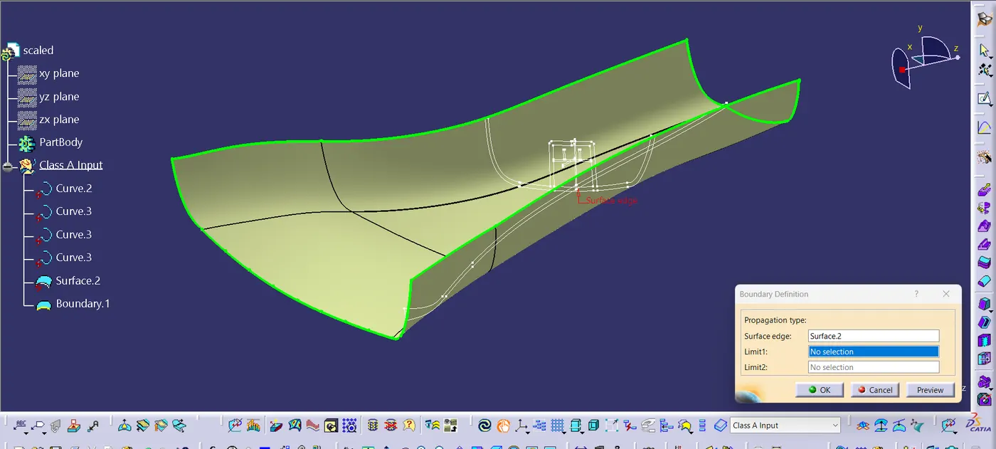
The class A surface quality is found to be fine after visual inspection.
Step 2 : Create Tooling axis.
- Insert Geometrical set and rename to Tooling axis
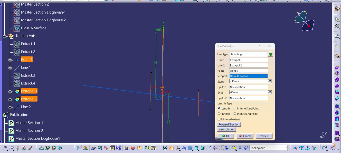
- Extract lines form the Master section and create point in between them, and using bisecting line and the point created make the Main tooling axis.
- Create Lifter tooling axis also.
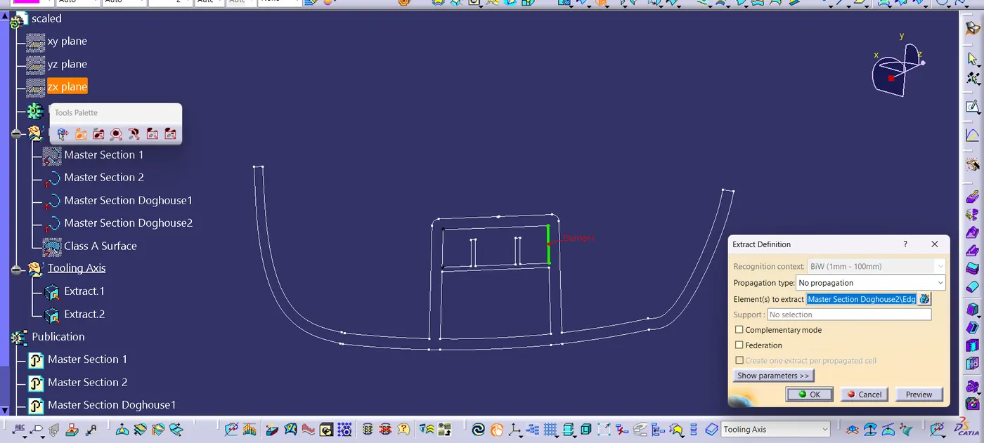
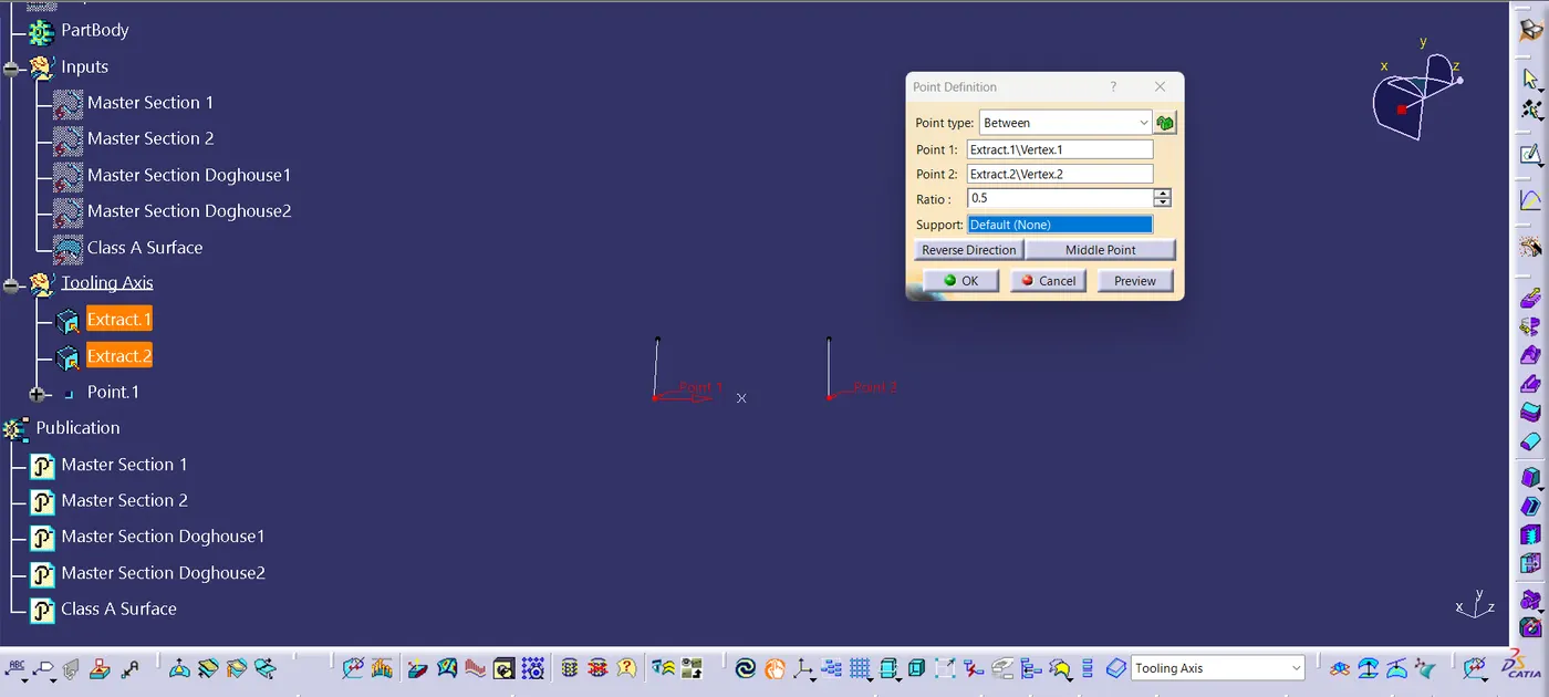
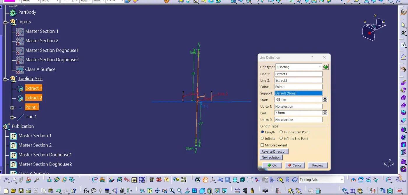
Step 3 : Offset the Class A surface to 2.5 mm which is the thickness of the part.Check for missing patches and clear them.
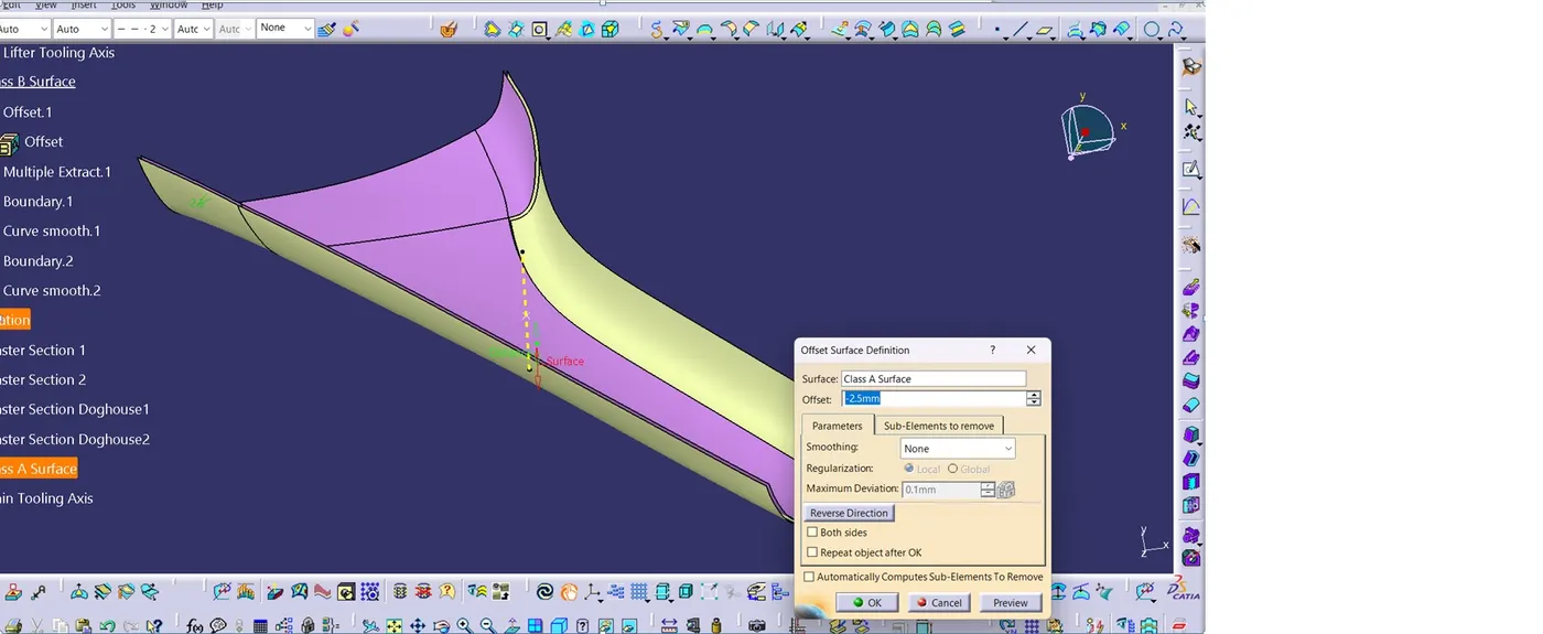
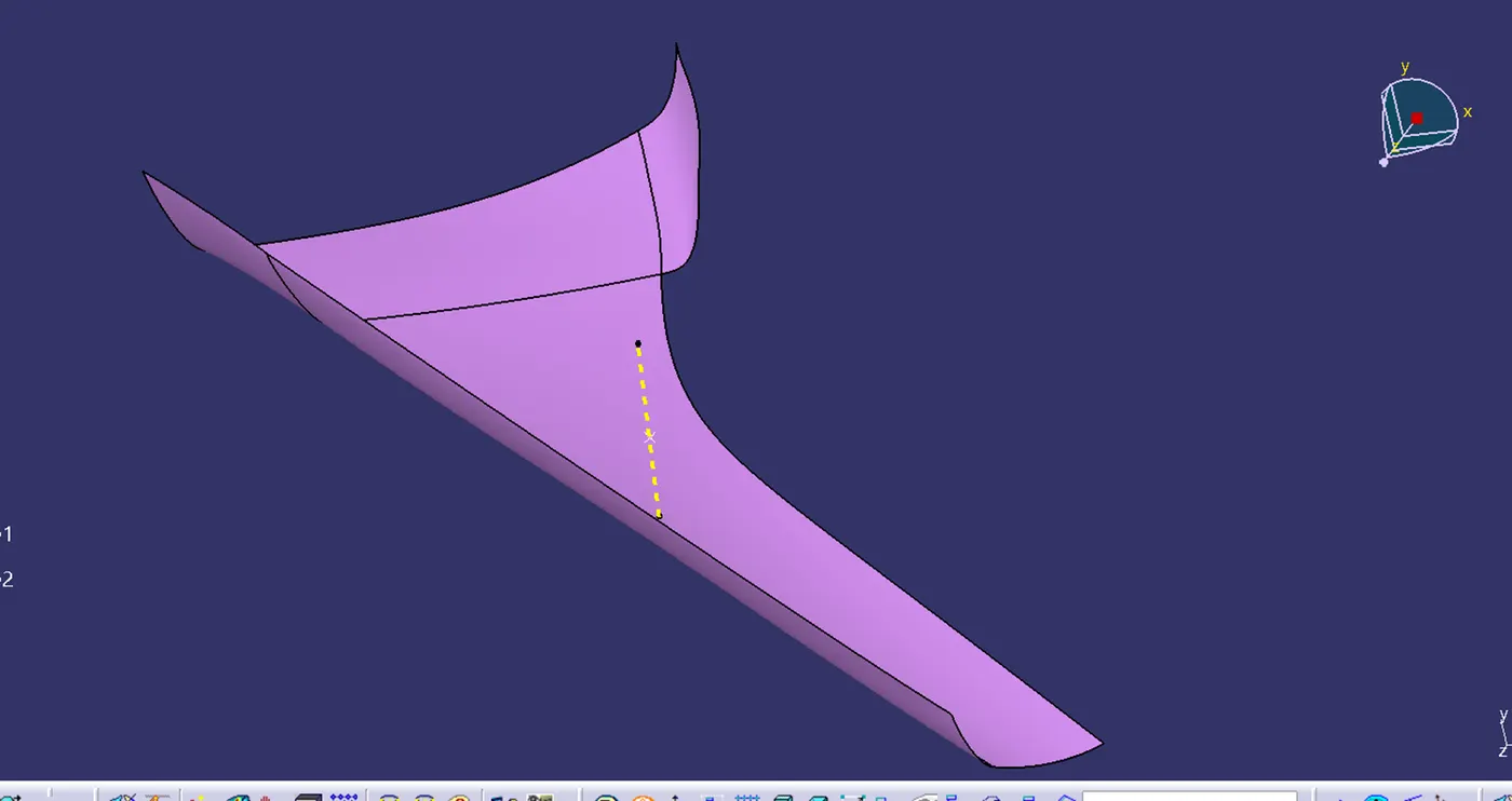
Here we can see that the entire patch is missing, which we have to clear.
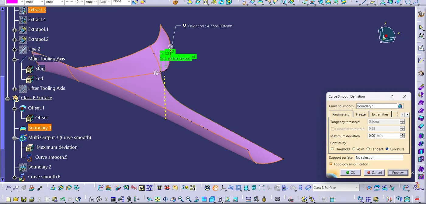
- First create the boundary on the Offsetted B surface and smoothen them using 'Curve Smooth command
- Since we have only a profile and a guide curve we use 'Sweep command
- After Sweep join them together to get the B surface and check for open boundaries.
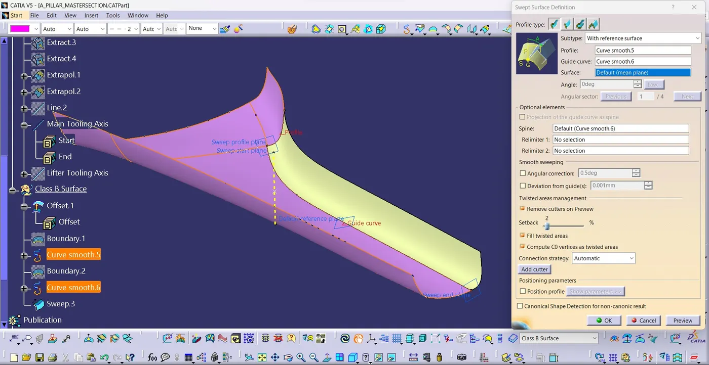
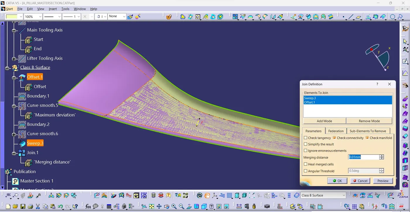
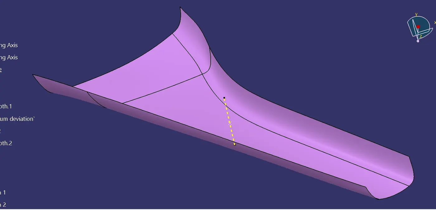
Step 4 : Creating Class C surface and joining it with class A
Insert a new geometrical set for class C surface.
Using Sweep command create the Class C and then Trim and join it with class A.
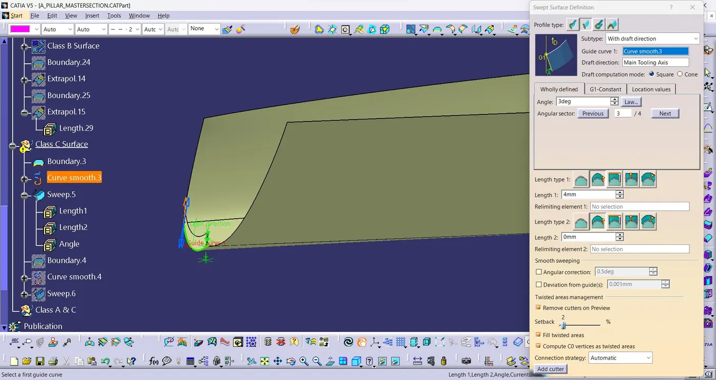
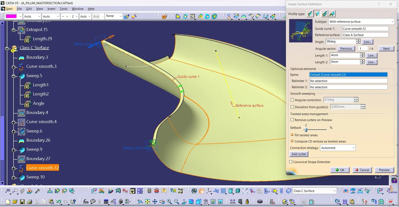
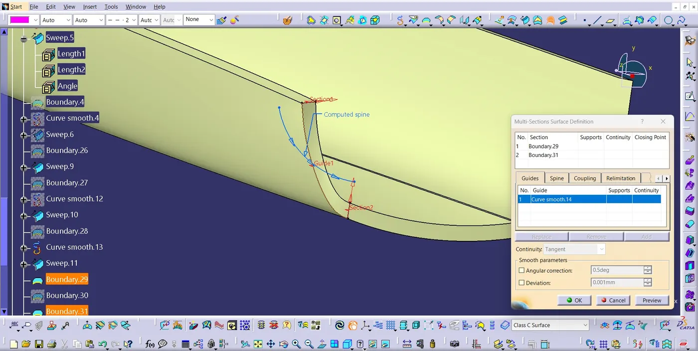
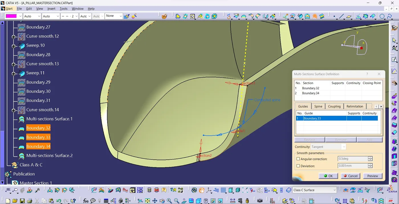
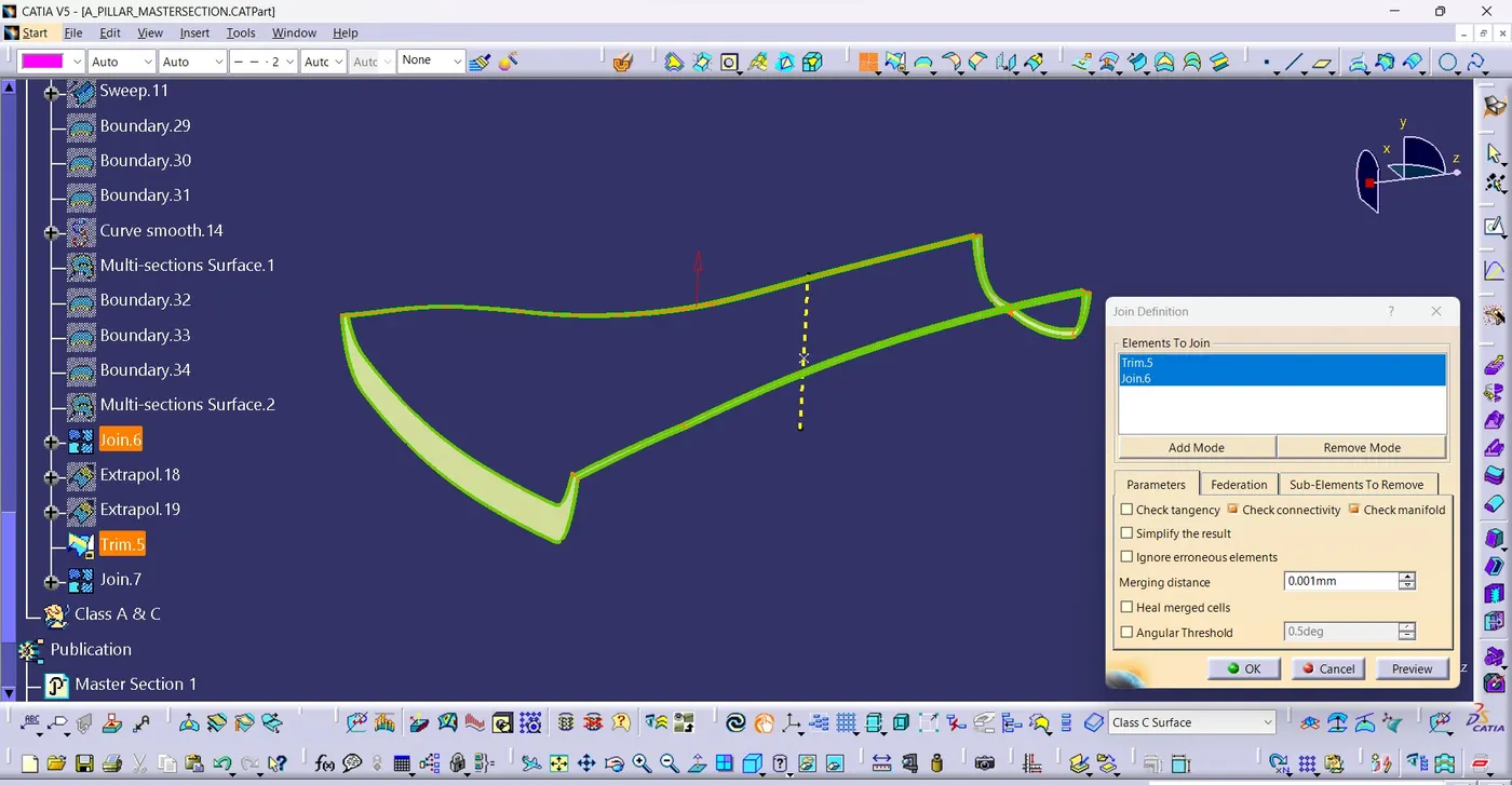
Step 5 : Creating Closed part body
- Trim Class B with Class A & C, Extrapolate class B wherever needed for trimming.
- Once the closed surface is obtained check for open boundries and using 'Close Surface' command convert closed surface in to solid part body.
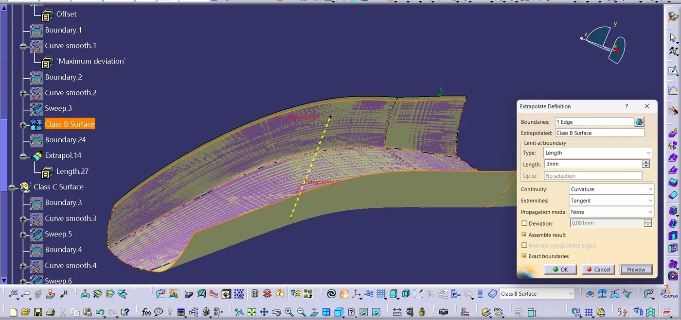
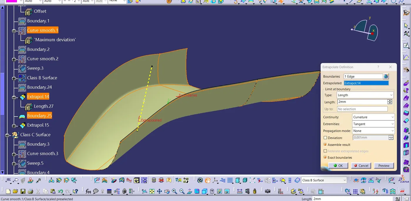
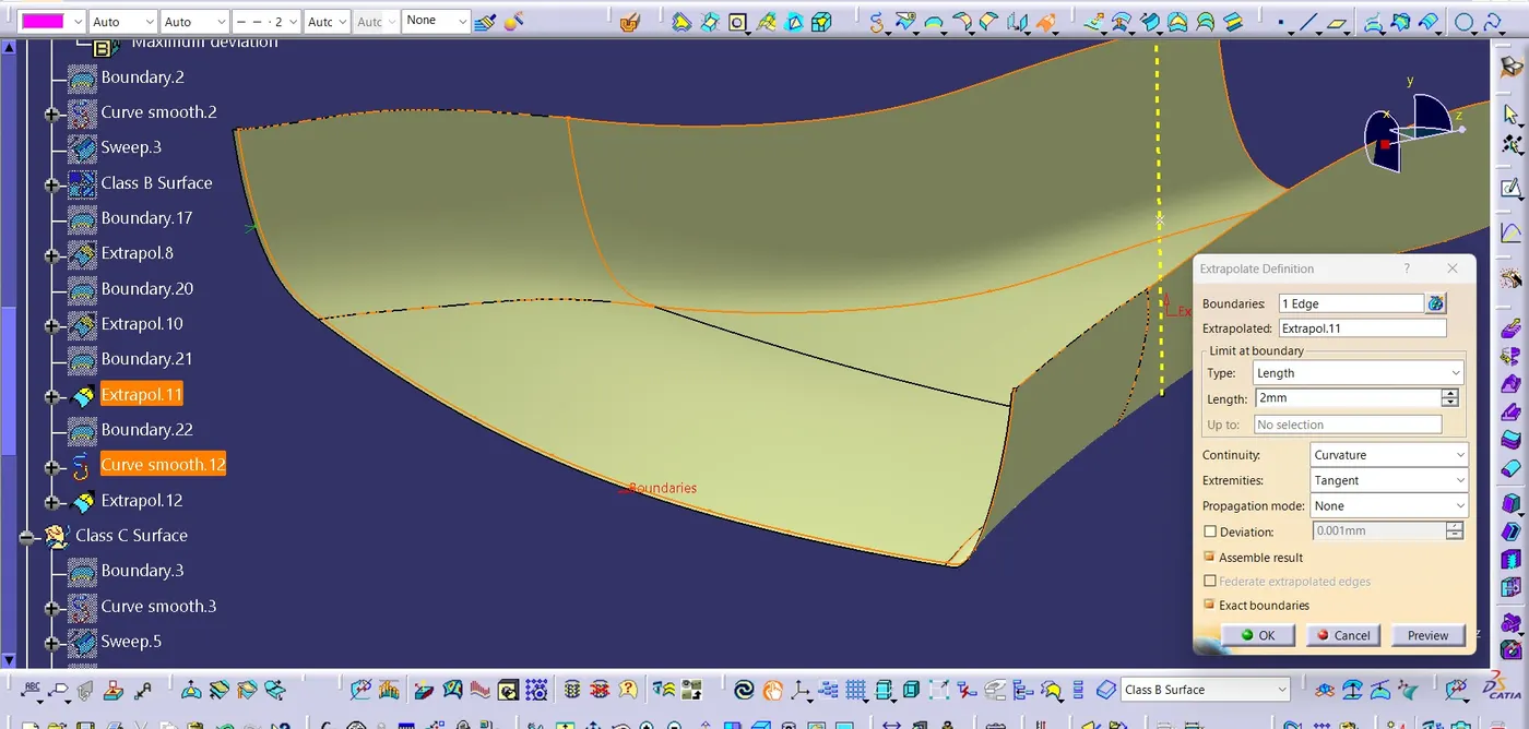
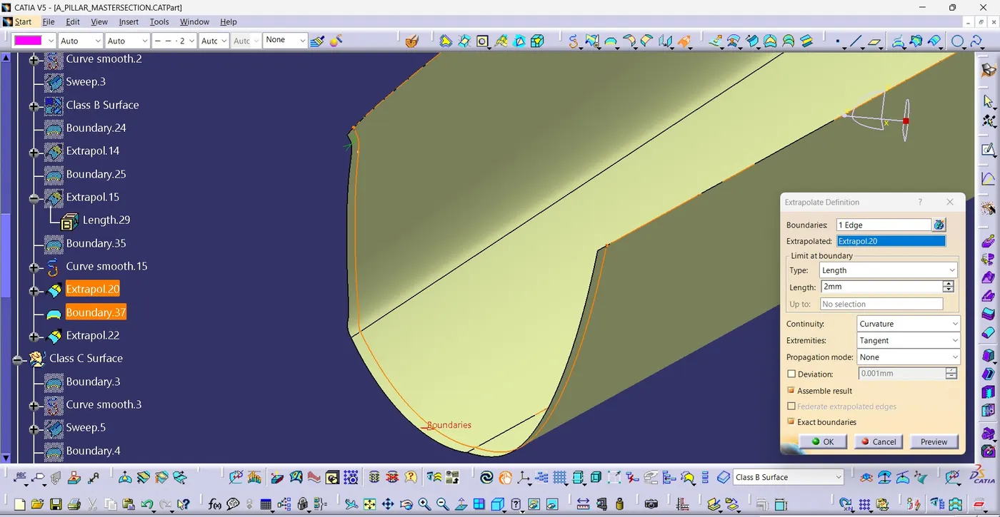
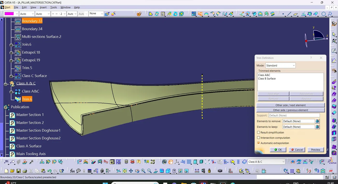
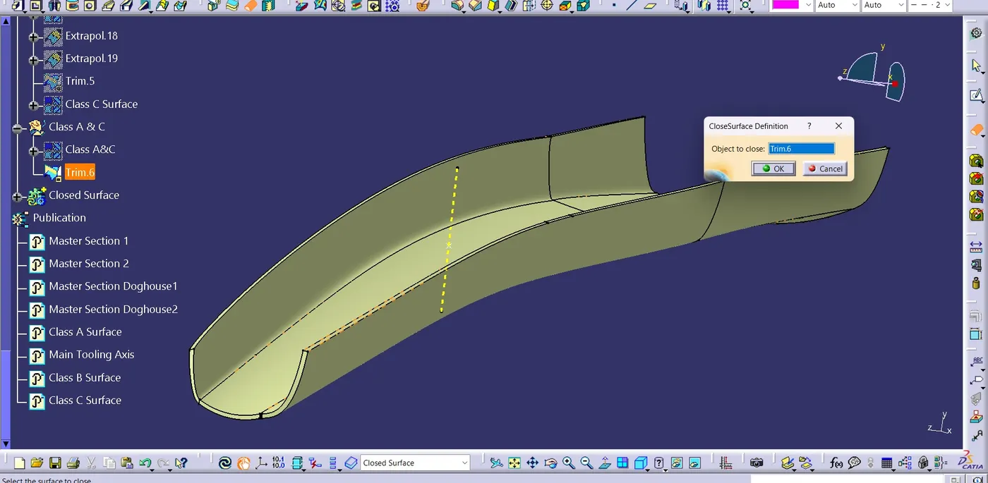
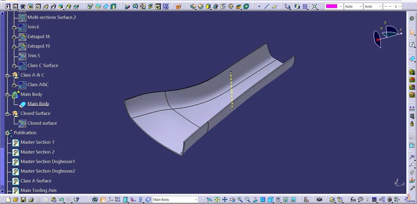
Step 6 : Conduct the draft analys
- The draft analysis was conducted and the class B surface was clearing the mininum draft of 3 degree very well.
- The C surface some portions were having negative draft due to the class A surface.
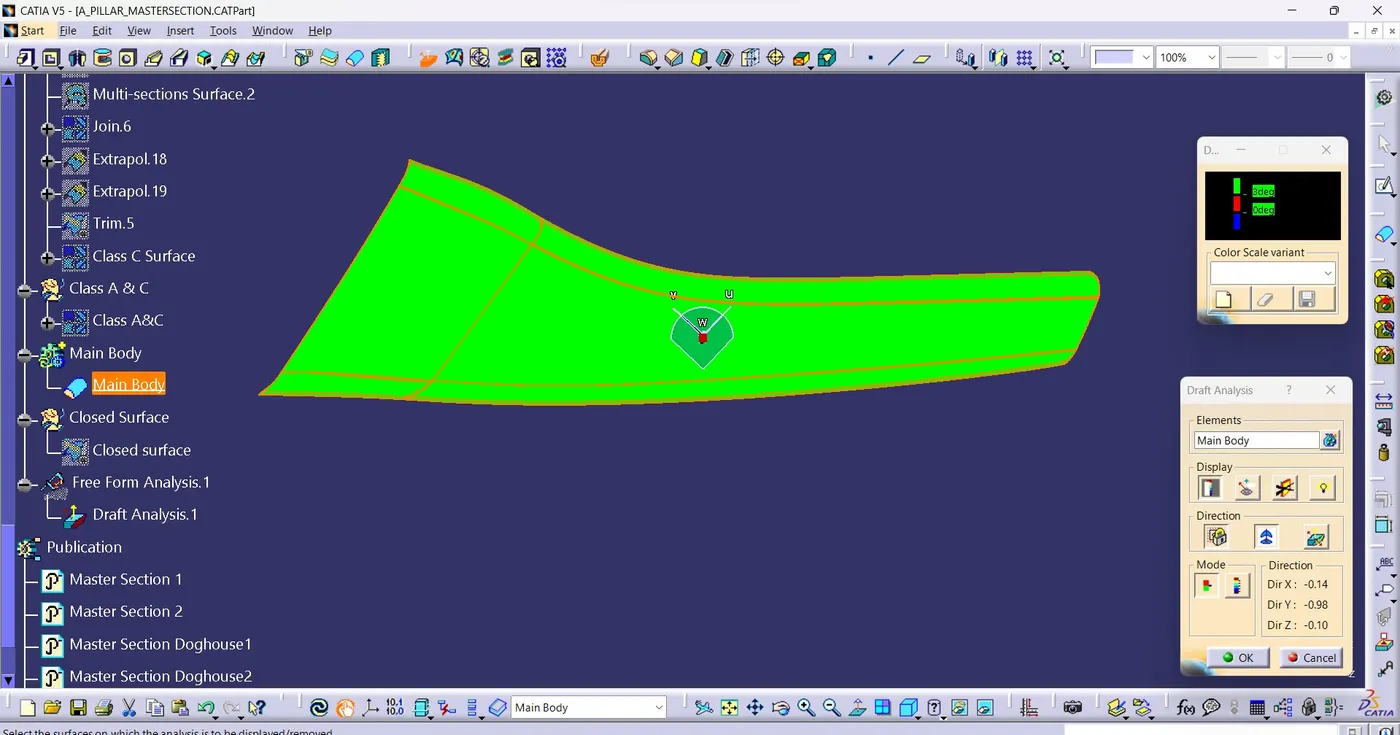
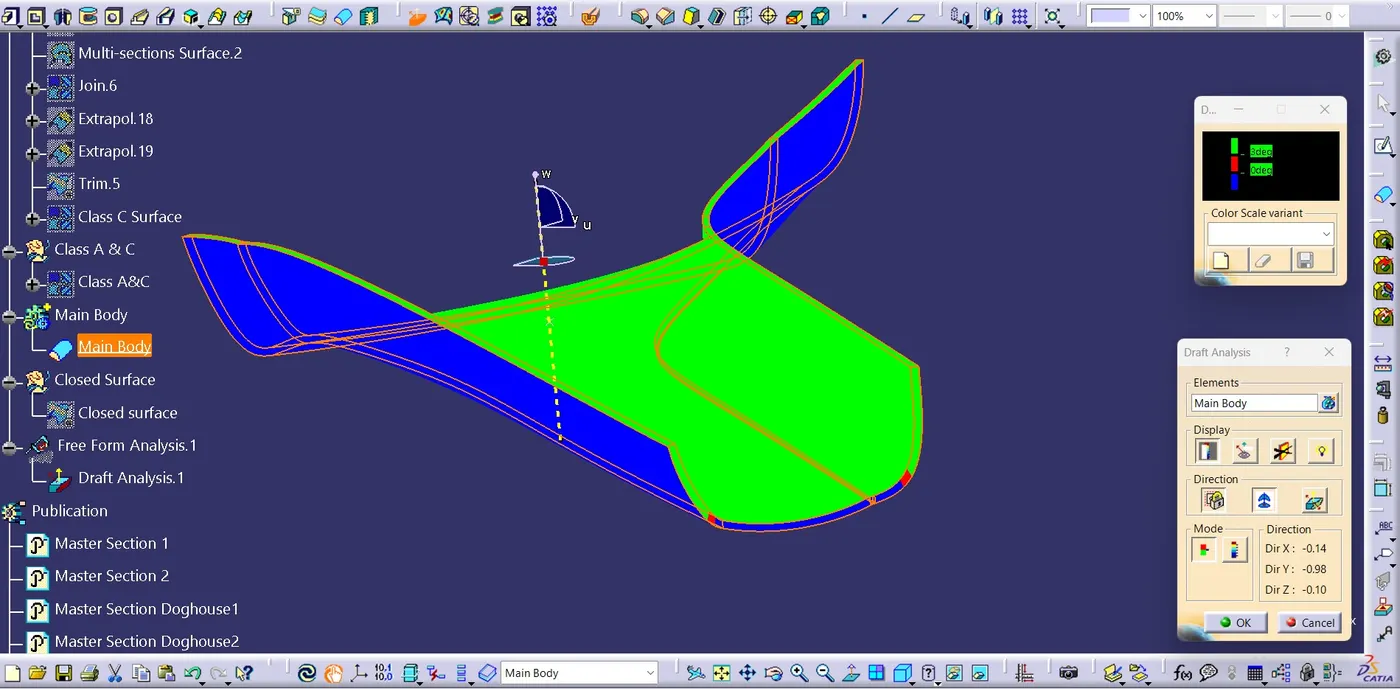
Class A draft analysis
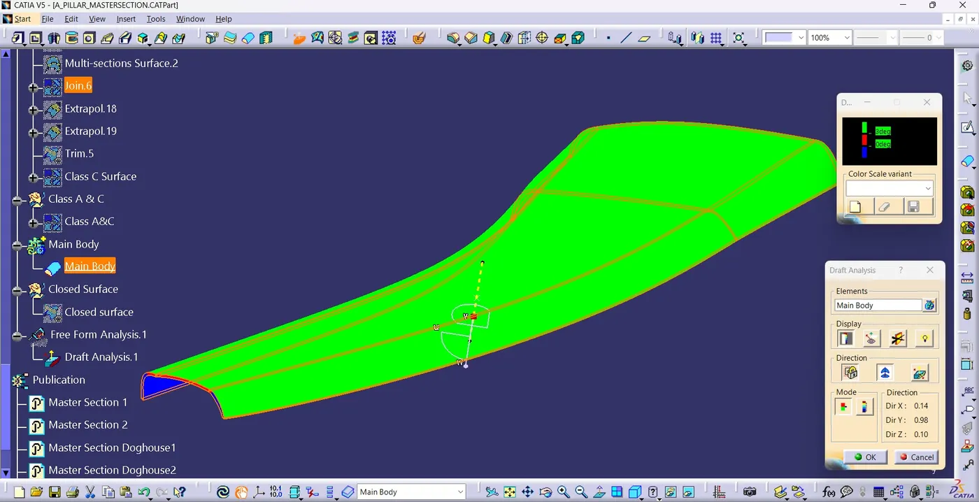
Step 7 : Creating Dog house.
- Insert a gometrical set for doghouse.
- Insert the sketch positioning and using the master section draw the dog house using 'Project 3D element' command.
- After makeing a the sketch constrain extrude the surface.
- Insert a plane where the dog house back should and insert sketch positioning to draw the back of the dog house.
- After sketching extrude it and tirm it
- Insert another sketch position to draw the front of dog house from master section and split the fornt to get the dog house surface.
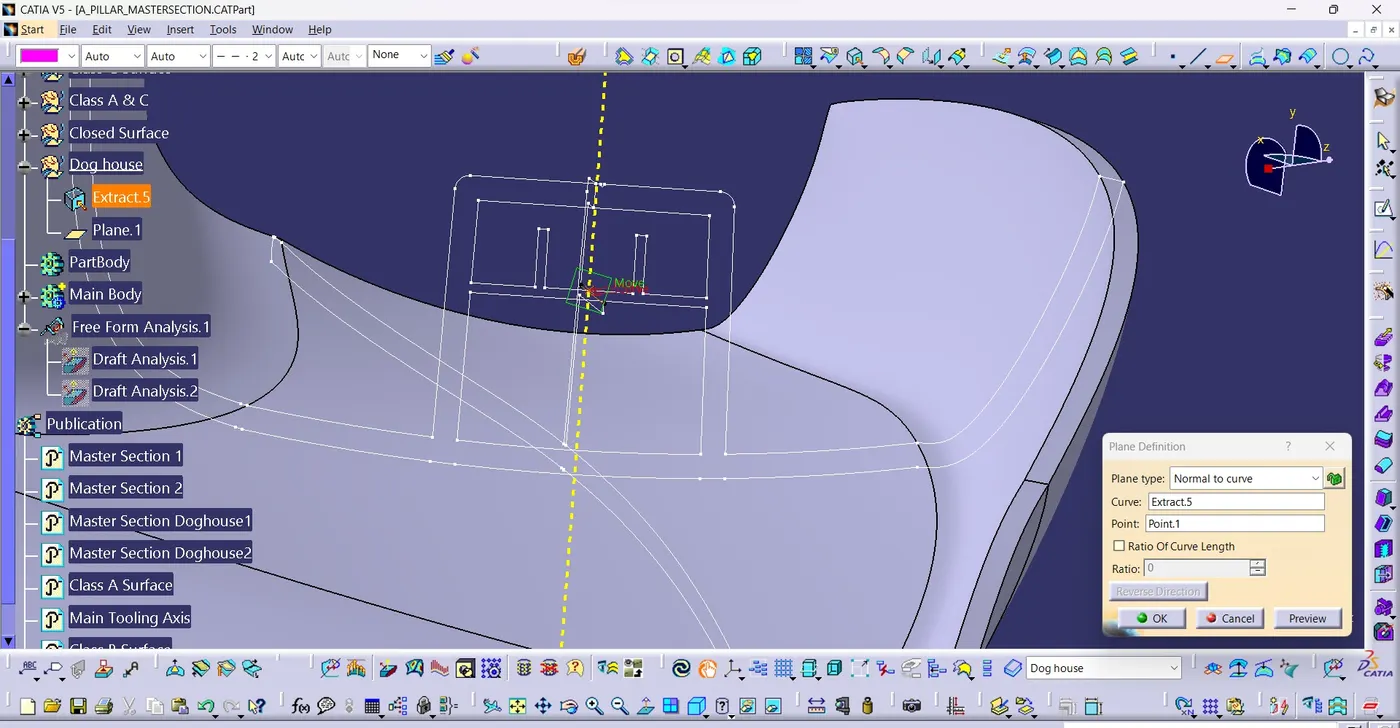
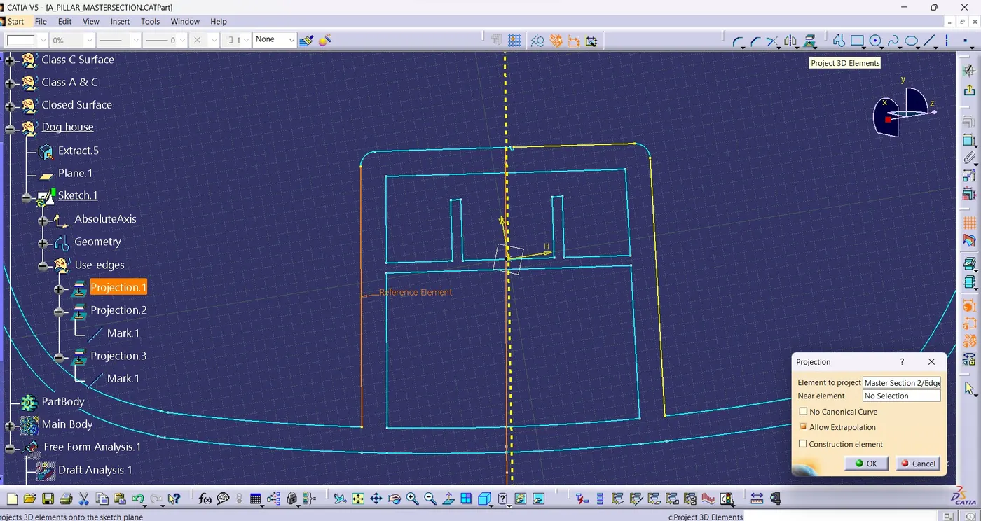
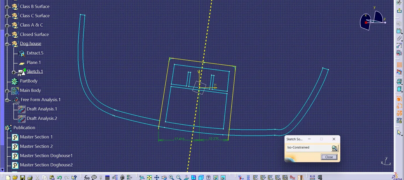
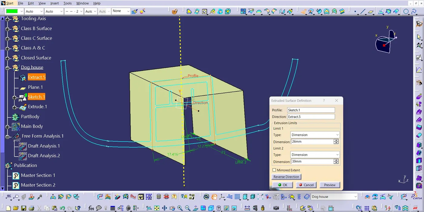
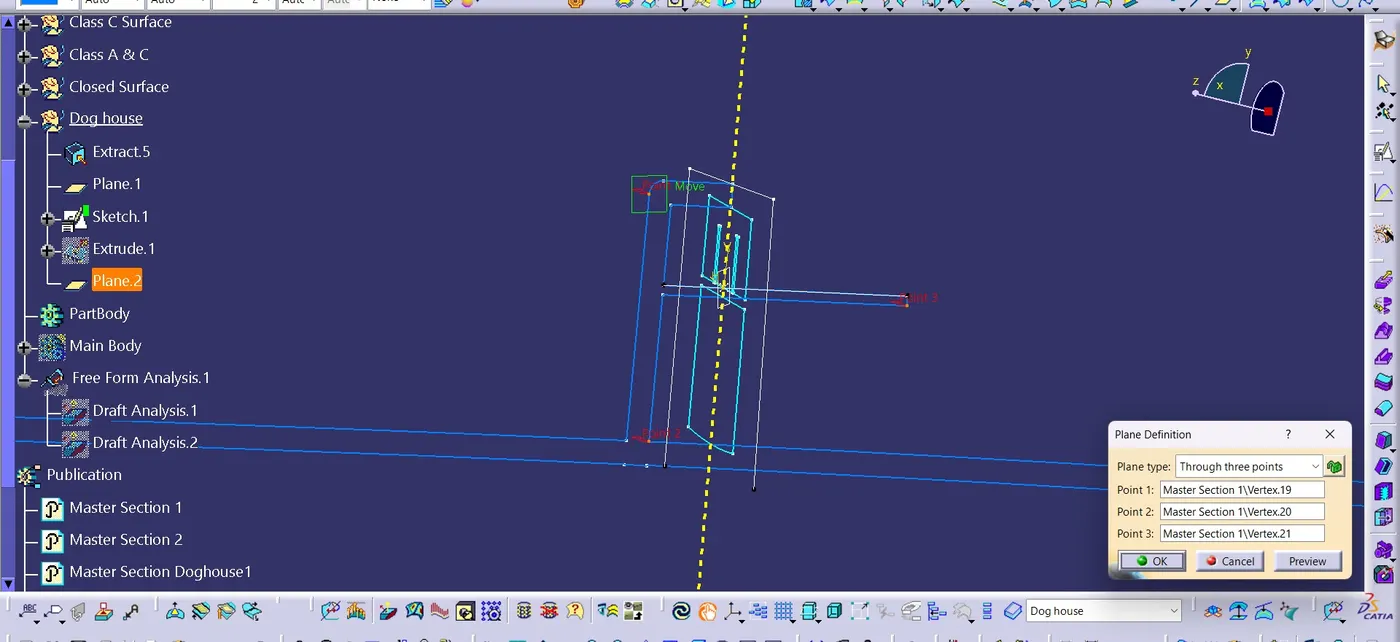
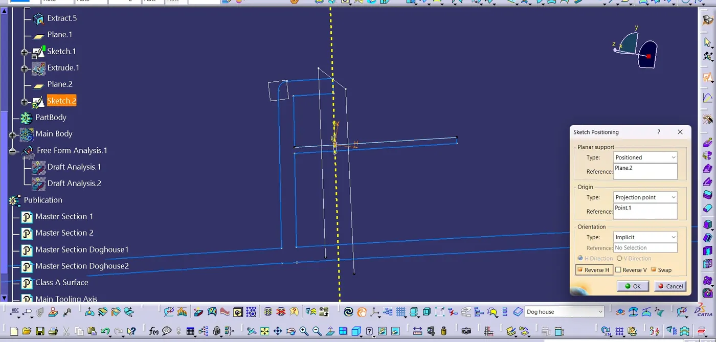
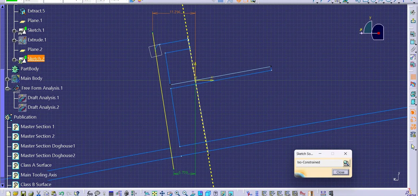
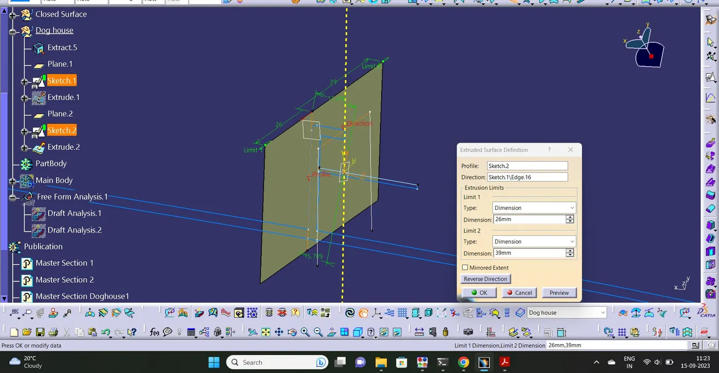
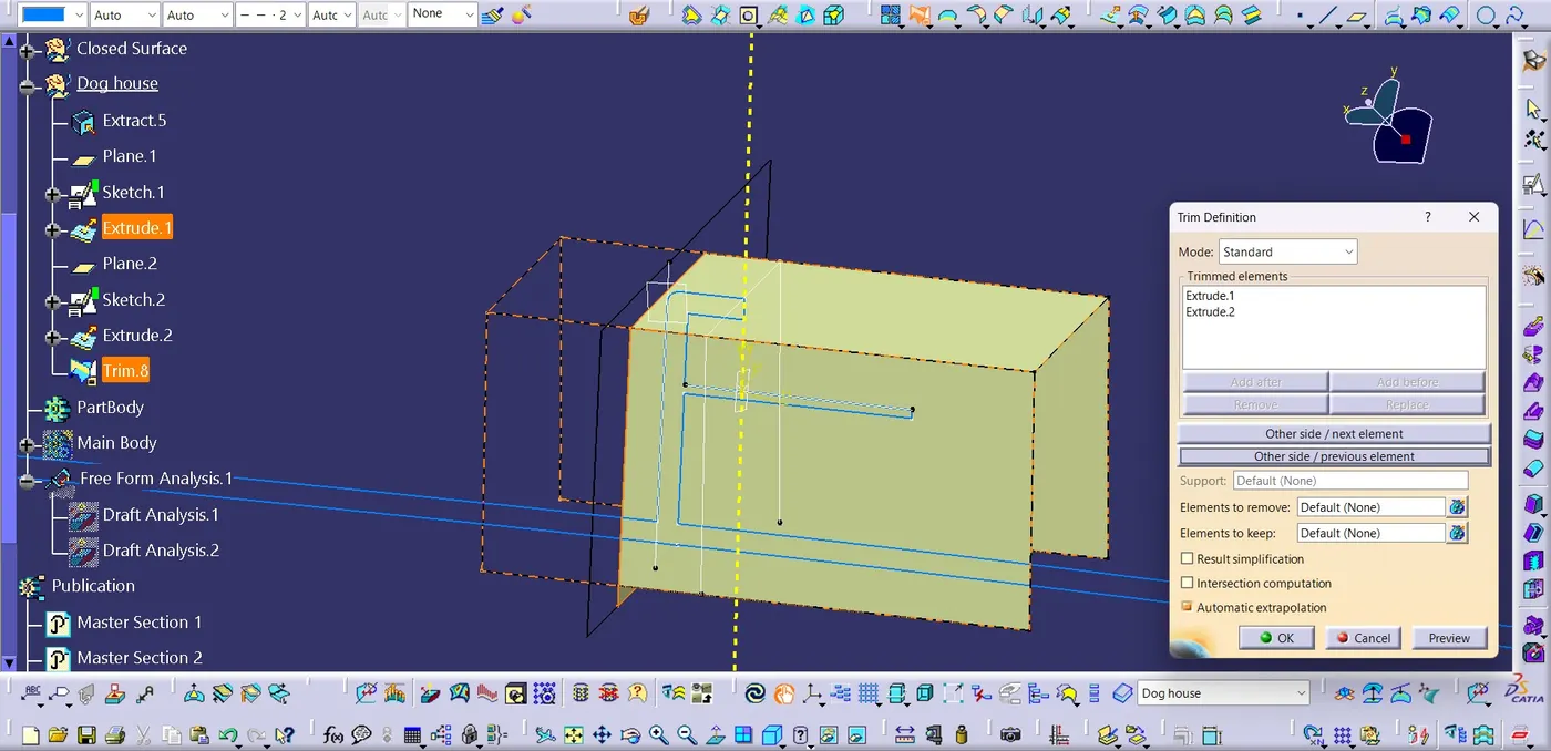
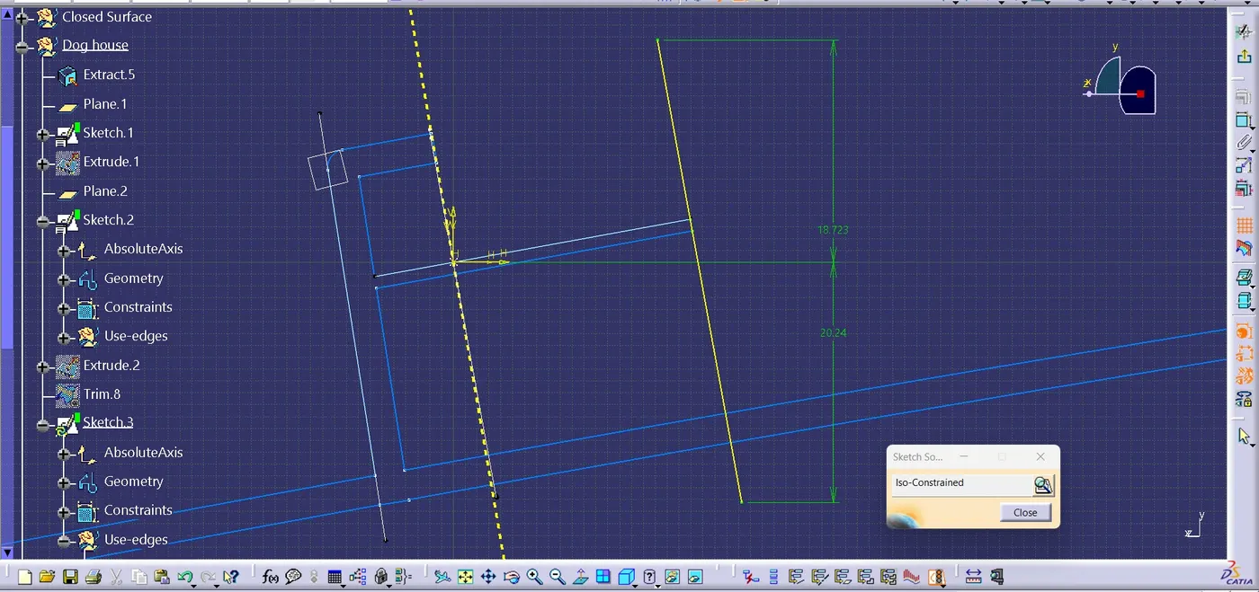
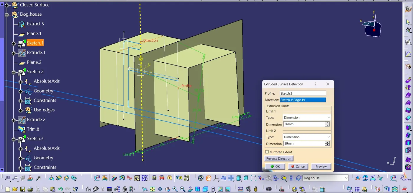
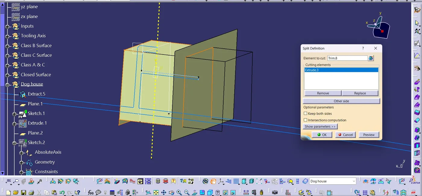
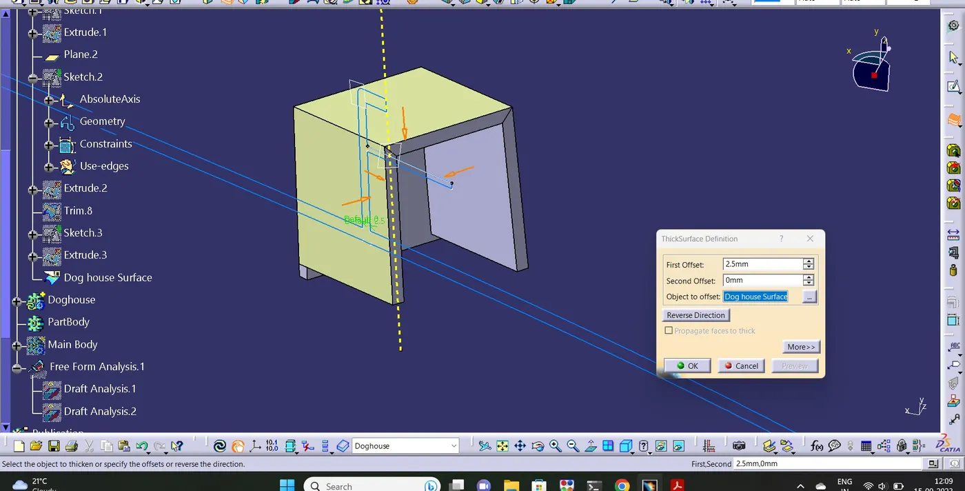
Step 8 : Thicken the surface to get solid body and define the designing parameters to the dog houde.
- Insert a new body for dog house.
- Thicken the surface to 2.5 mm using 'Thick surface' Command and check with master section.
- Give the inside draft of 0.5 degree and minimum fillet of 0.5 to inside surface.
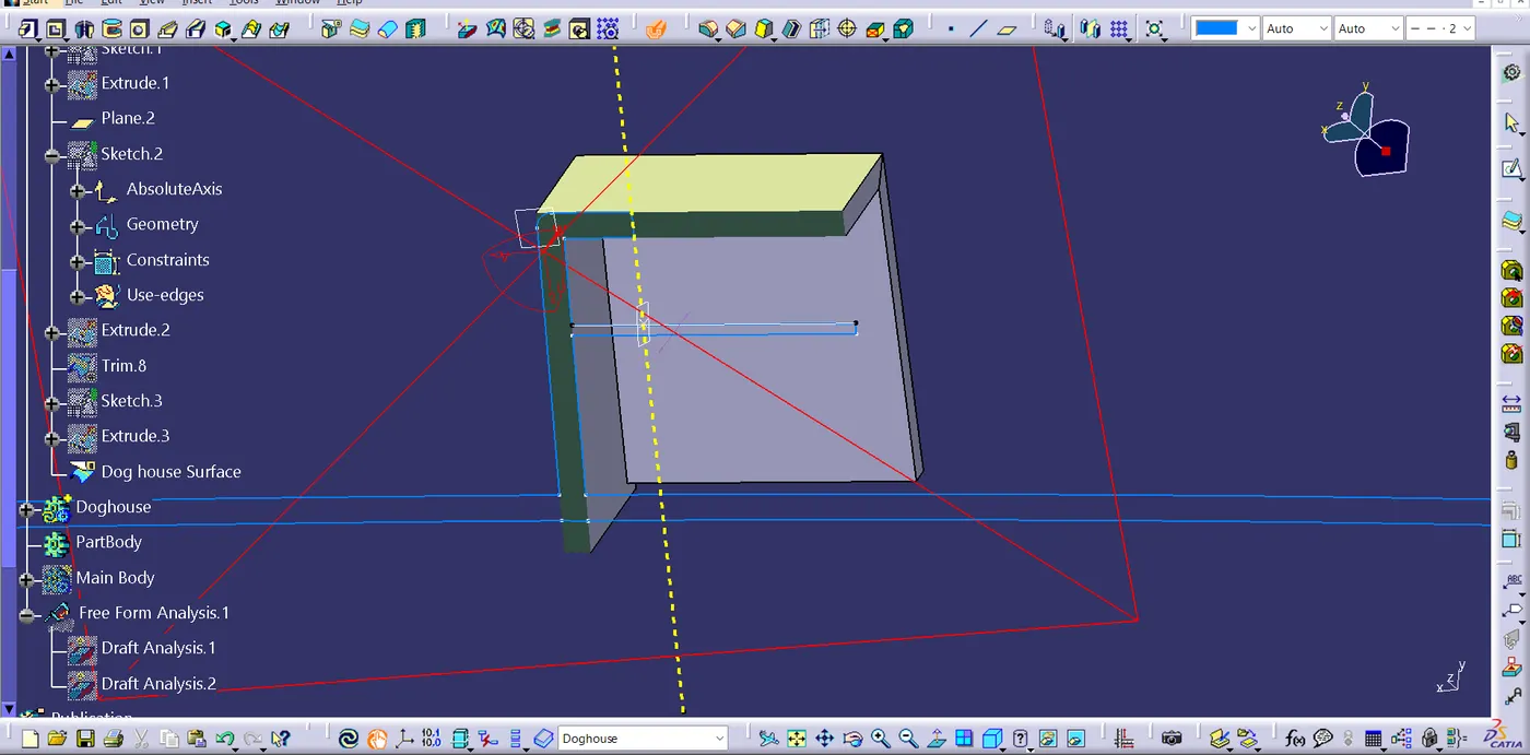
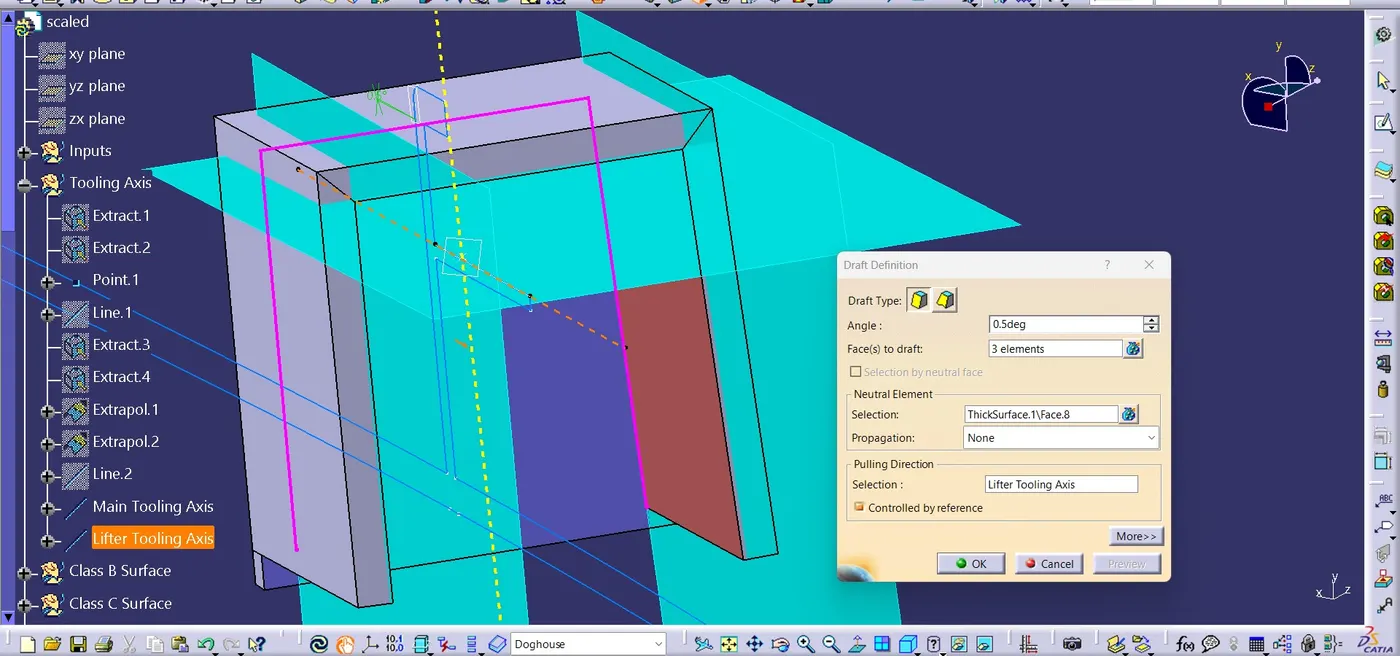
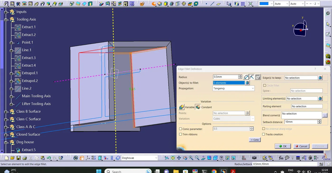
- To make the bottom protion extract the inside faces of the doghouse and offset to 1.5 mm since 40% of 2.5 mm is 1 mm, which should be the thickness at the surface intersecting.
- Etract the surface from Class B and offset it to a distance of 4 mm.
- Then trim both the surface and usign this surface and split command remove the solid part.
- Give draft to the removed portion and minimum fillet of 0.5mm.
- Give edge fillet of 0.5+2.5 = 3 mm for the outer edges.
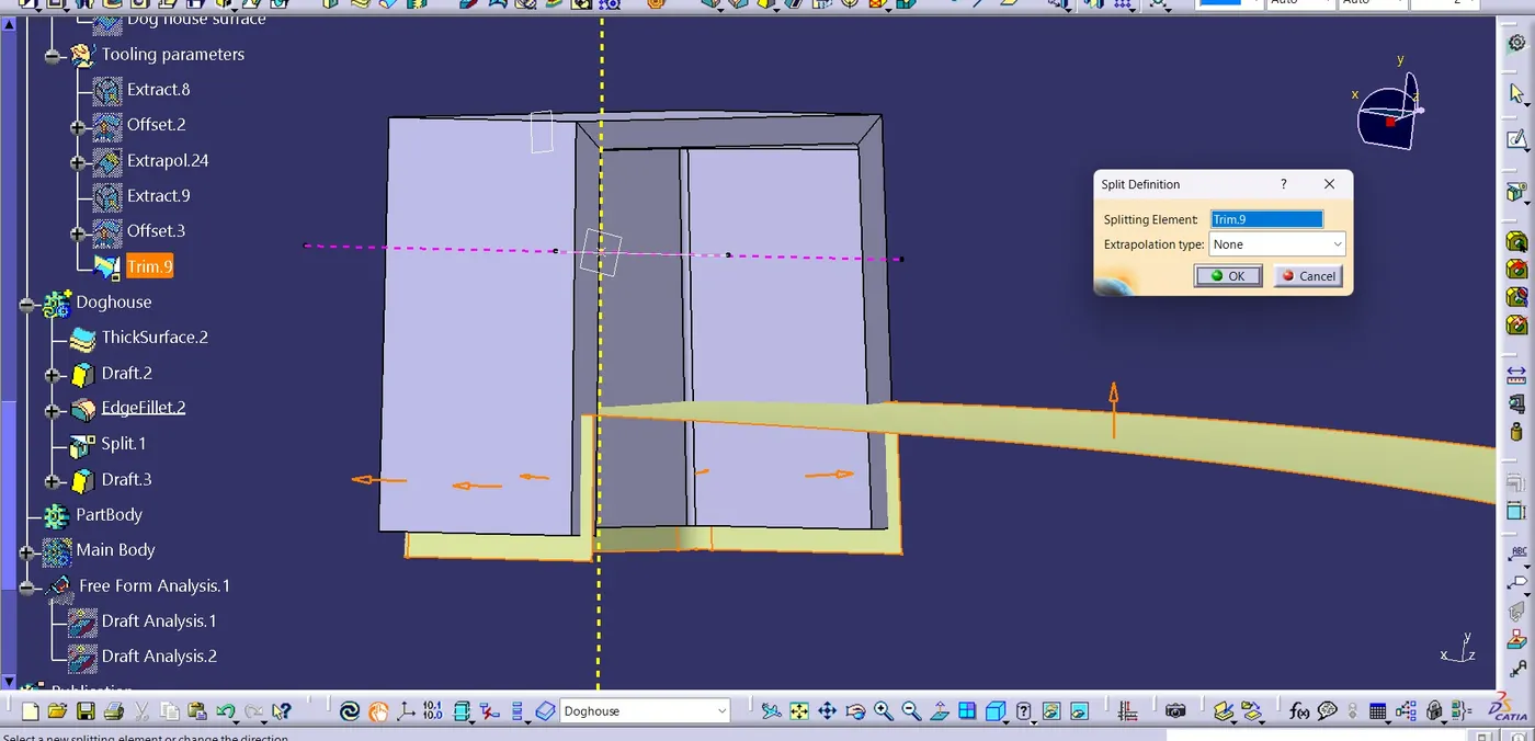
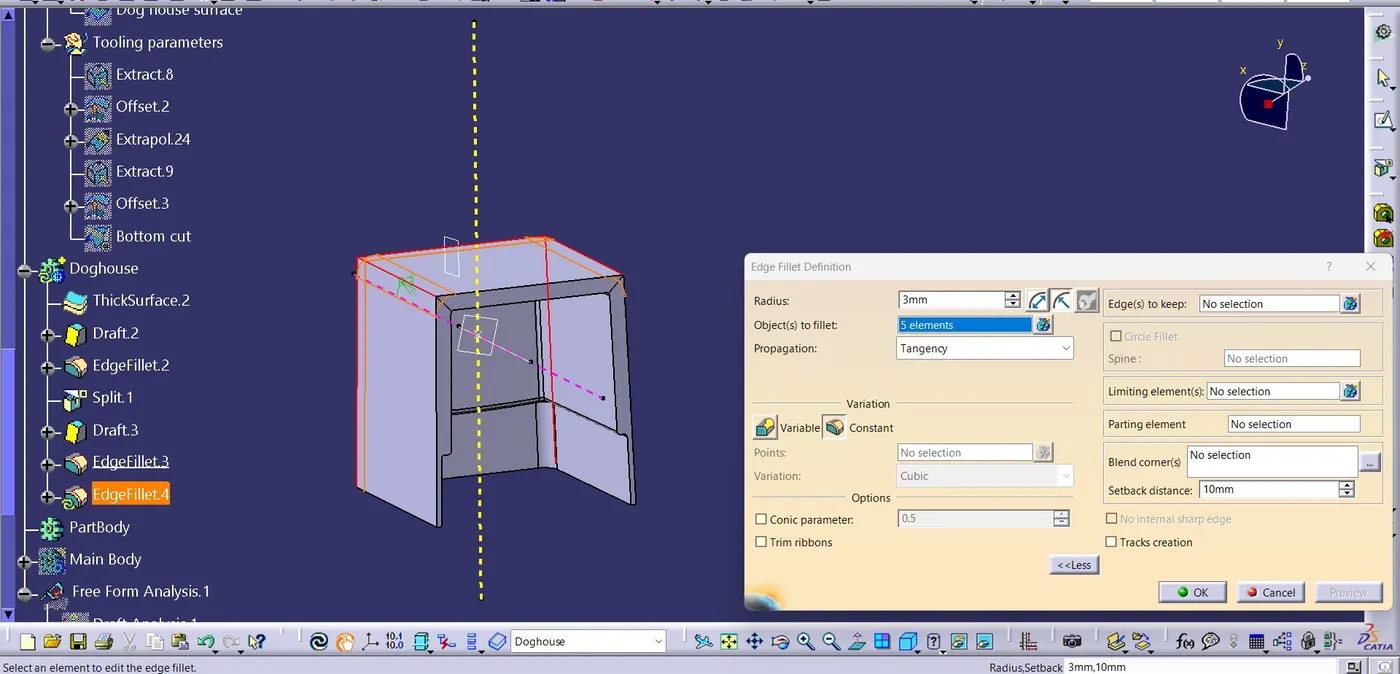
Step 9 : Creating push pin slot
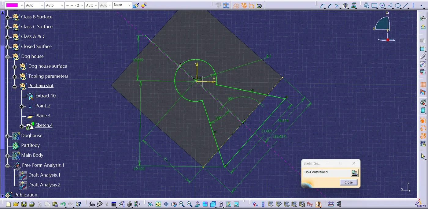
- Insert a geometrical set for creating pushpin slot and on the top surface of doghouse createa a sketch for slot.
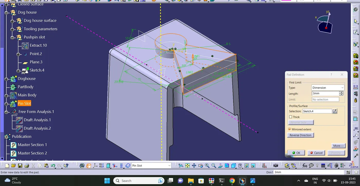
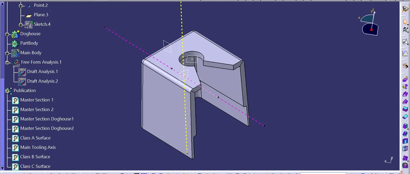
- Insert a body and pad the sketch give draft and remove the pad from the doghouse.
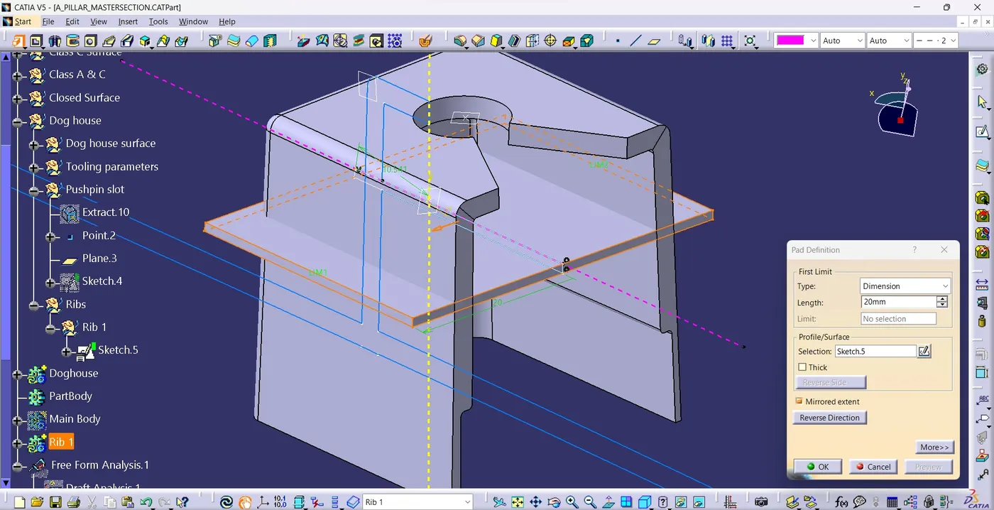
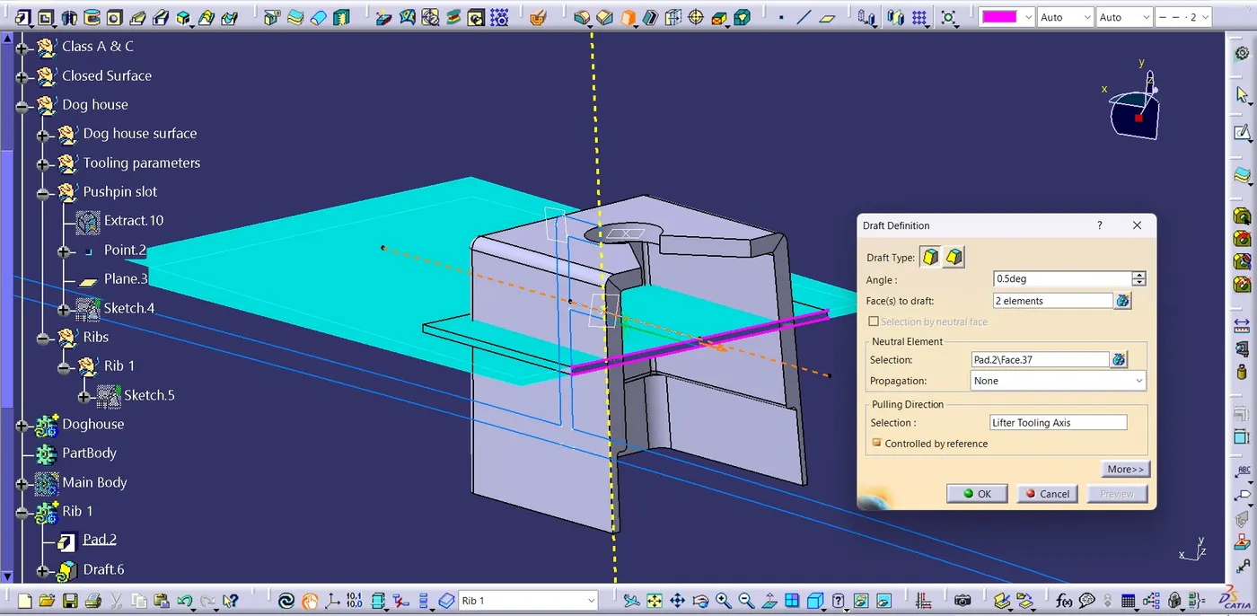
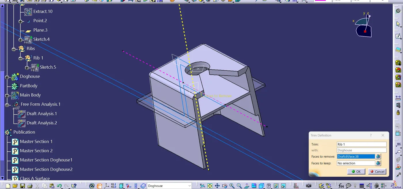
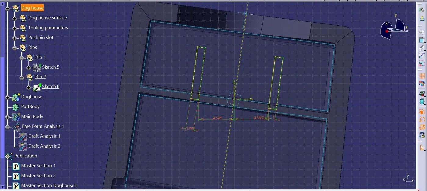
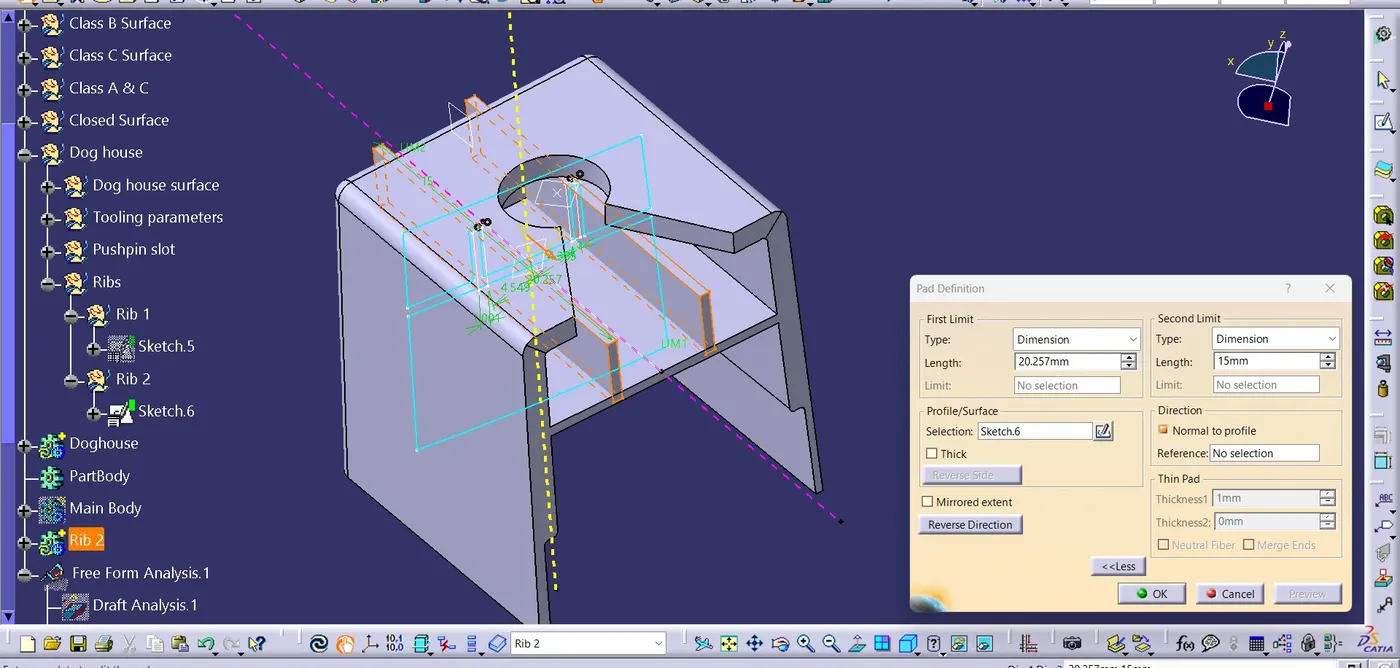
Step 10 : Creating rib for dog house.
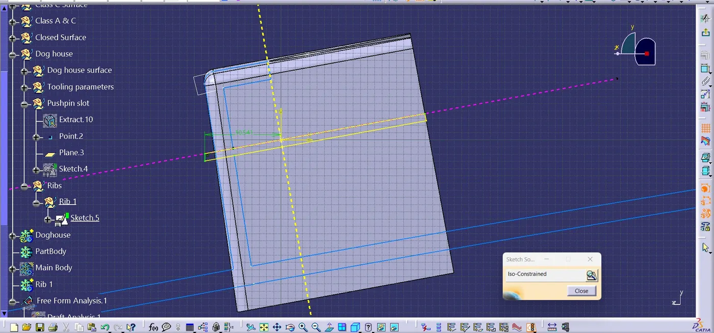
Insert a geometrical set for rib 1 and sketch the rib from the master section.
Using pad command extrude the rib , give draft of 0.5 degree and using union trim join it with the doghouse.
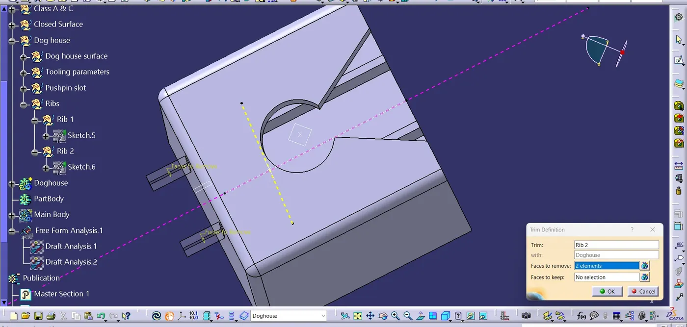
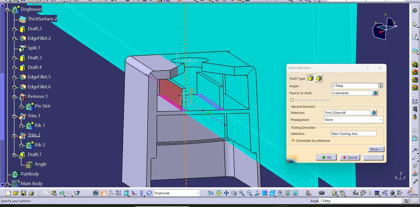
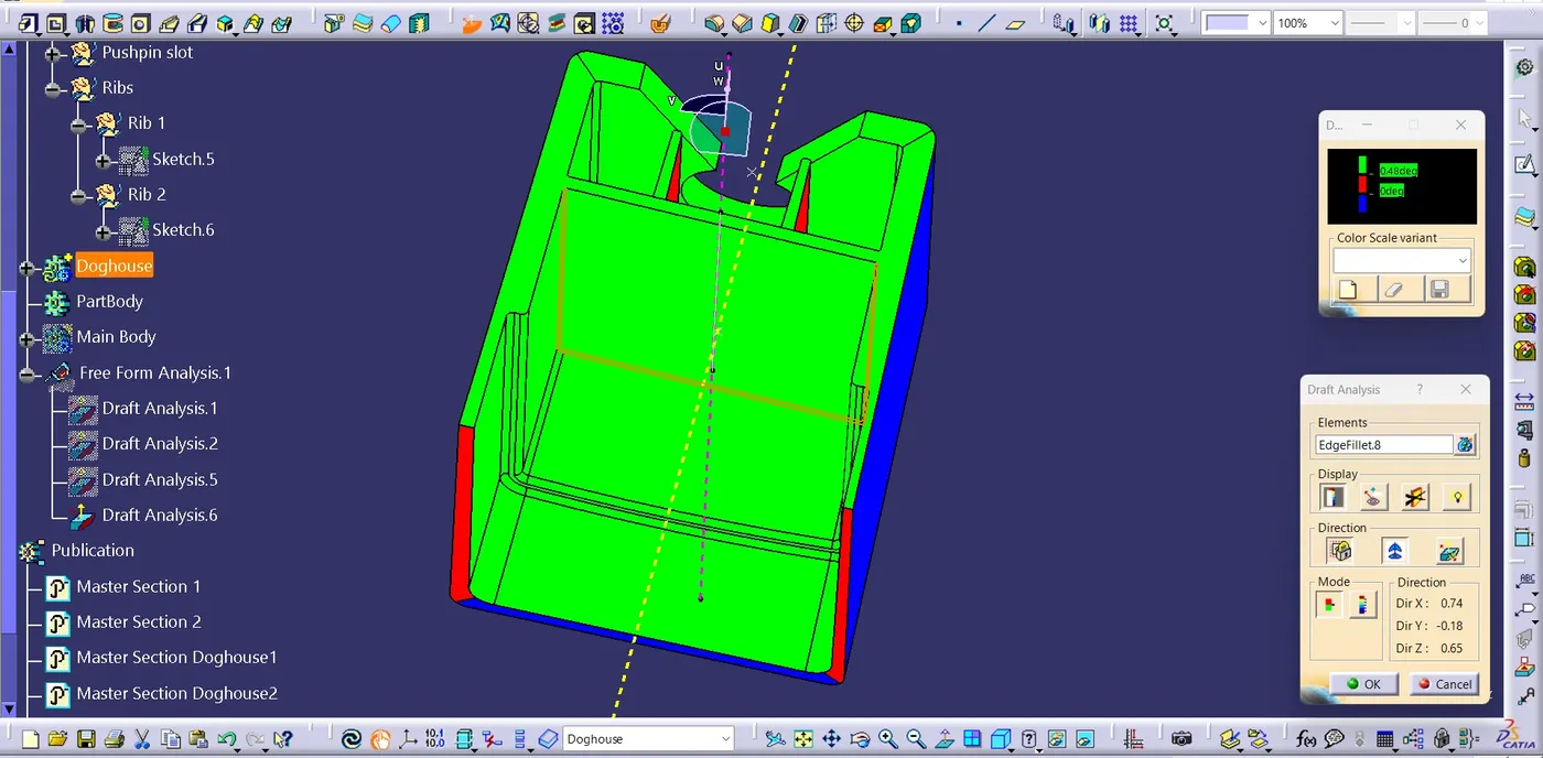
The draft analysis was conducted for the dog house
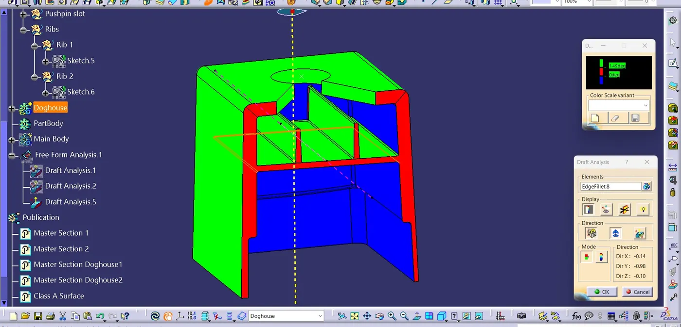
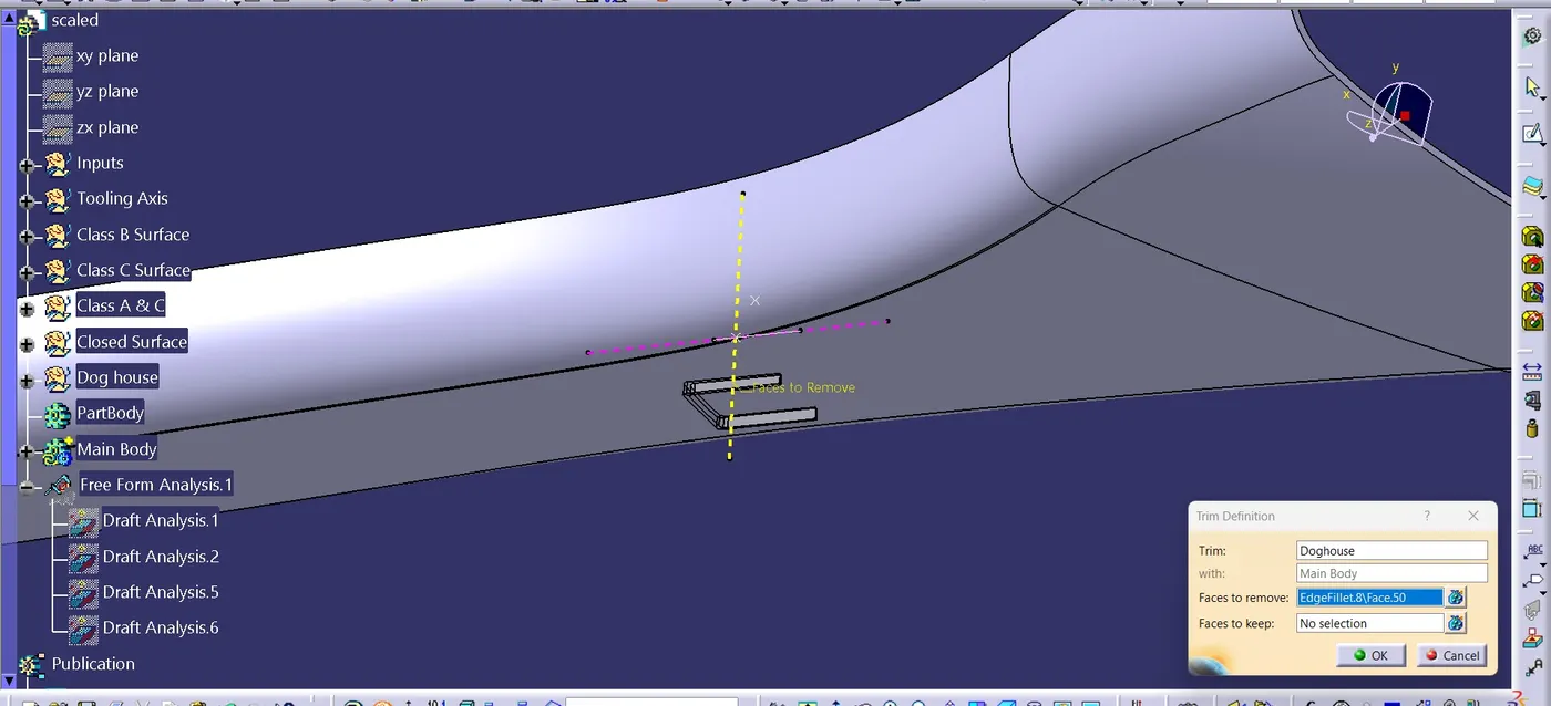
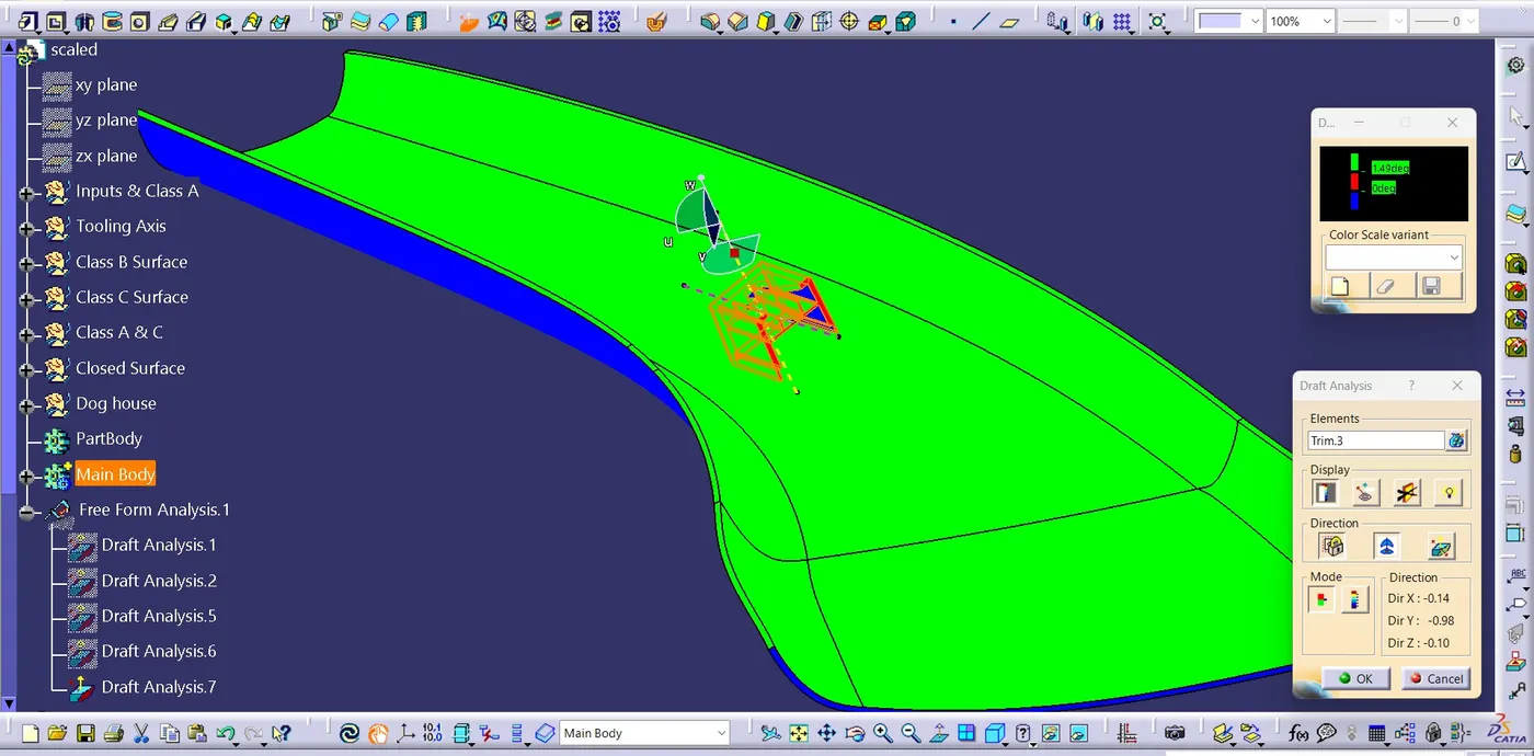
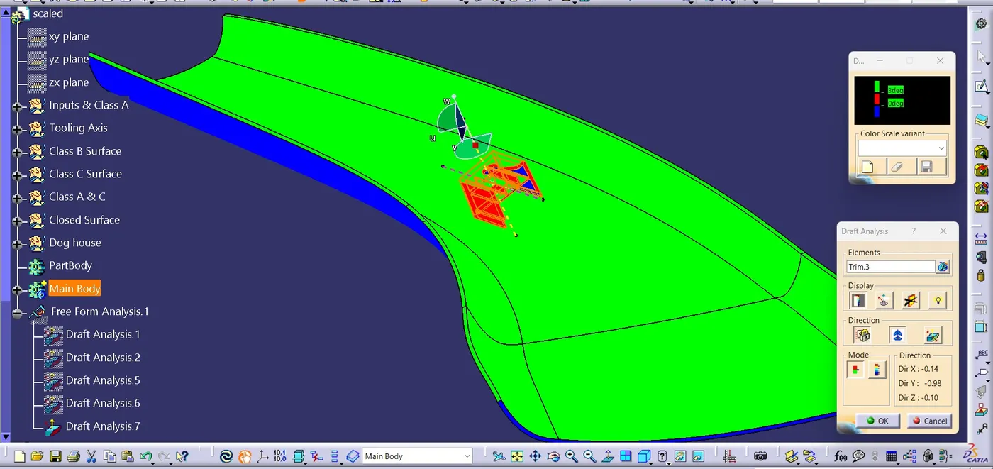
Step 10 : Union trim the doghouse to the main body and insert them in the part body.And do the draft analysis.
Front view
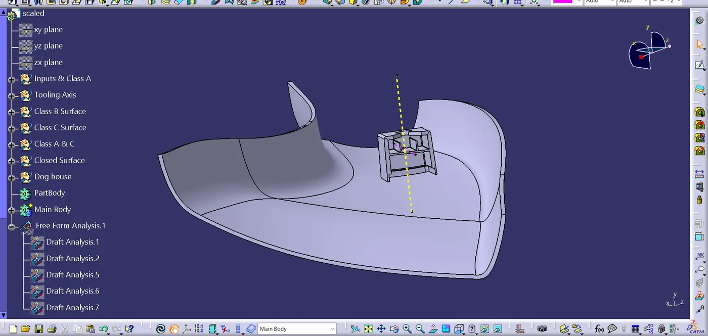
Top View
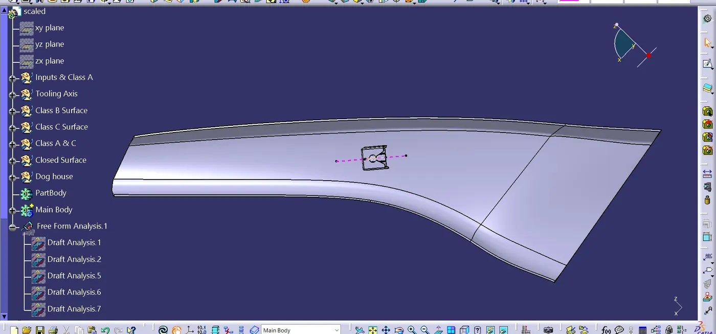
Back side view
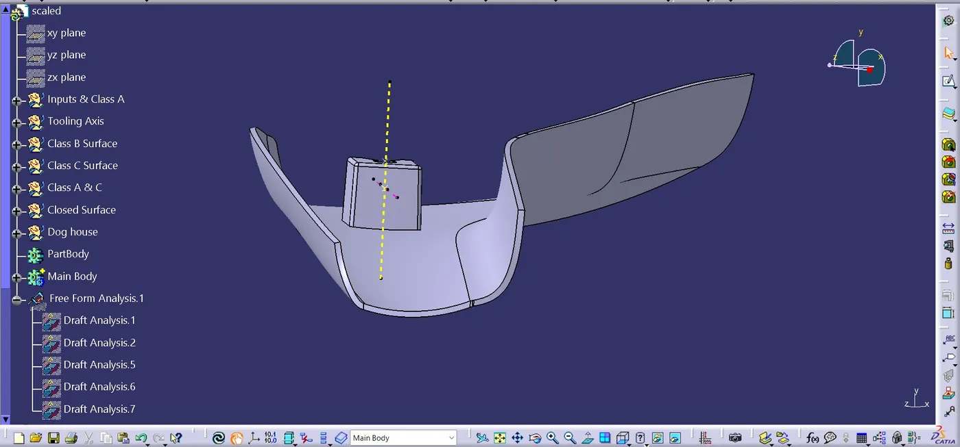
Bottom view
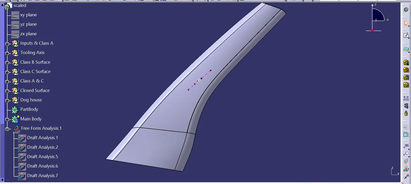
Isometric View
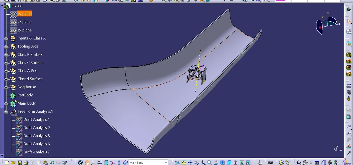
Tree Structure
CONCLUSION
Created a pillar design with master section given as the intersection sketch with class A Surface and create the tooling axis and perform the draft analysis.