Week 10 - Challenge 2- Attachment Feature Creation (Dog House)
AIM
To create the Dog House for the Door Trim considering the design rules.
THEORY
Dog House
In plastic injection molding, a "doghouse" is a term used to describe a raised or thickened area on a plastic part. This raised area is strategically designed into the part to provide additional material and strength in areas where engineering features like snaps, locators, fasteners, or other elements will be attached. It helps prevent deformation, breakage, or distortion of the plastic part during the molding process, ejection from the mold, and subsequent assembly.
Functions and Applications of Doghouses:
-
Enhanced Strength: Doghouses provide extra material in specific areas to reinforce the plastic part, making it more durable and resistant to stresses that might occur during production and assembly.
-
Attachment Points: Engineering features such as snaps (interlocking mechanisms), locators (alignment features), and fasteners (screws, bolts) often need a solid base for proper functionality. Doghouses offer a stable platform for attaching these elements securely.
-
Preventing Breakage: Draft angles are typically applied to mold cavities to facilitate the easy removal of parts from the mold. However, this can lead to thinning of certain areas of the part. Doghouses can counteract this thinning by providing additional material where needed, reducing the risk of breakage during ejection from the mold.
-
Maintaining Aesthetics: Doghouses can be designed in such a way that they are on the B-surface (non-visible side) of the part. This preserves the aesthetic appearance of the visible surface while still providing the necessary structural support.
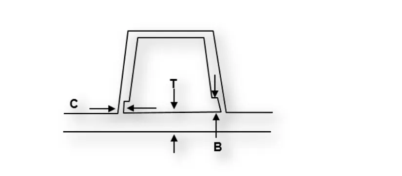
Design Criterias:
- C thickness should be 40% of the main wall thickness T
- Minimum width of the dog house is 12 mm.
- Height of B should be 3-6 mm
- Minimum draft for the do house is 1.5 degree to tooling axis.
PROCEDURE
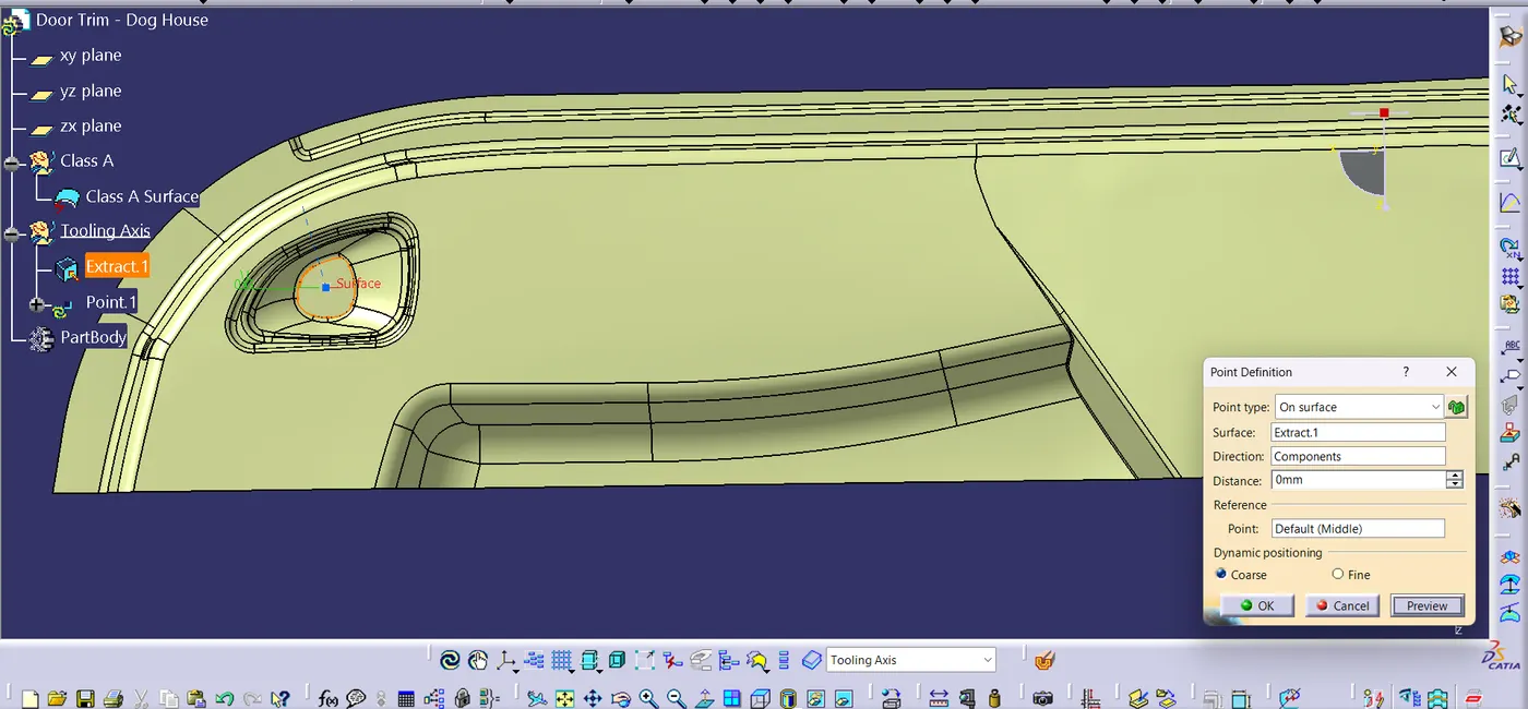
Step 1 : Create Tooling axis
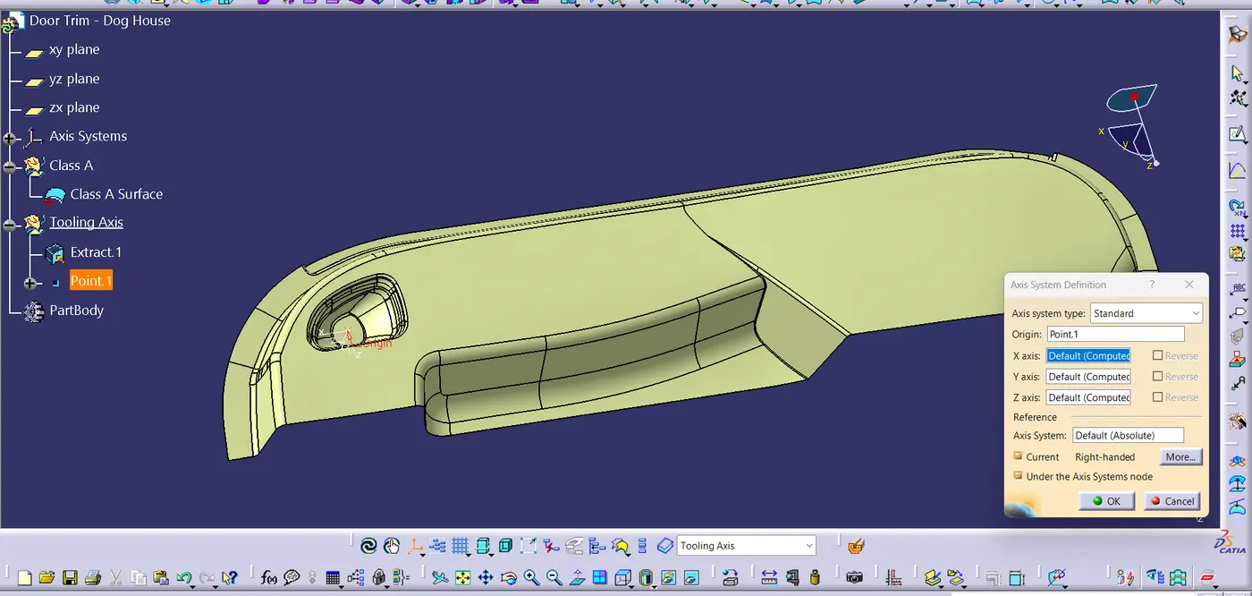
- Insert a geometrical set for creating tooling axis.
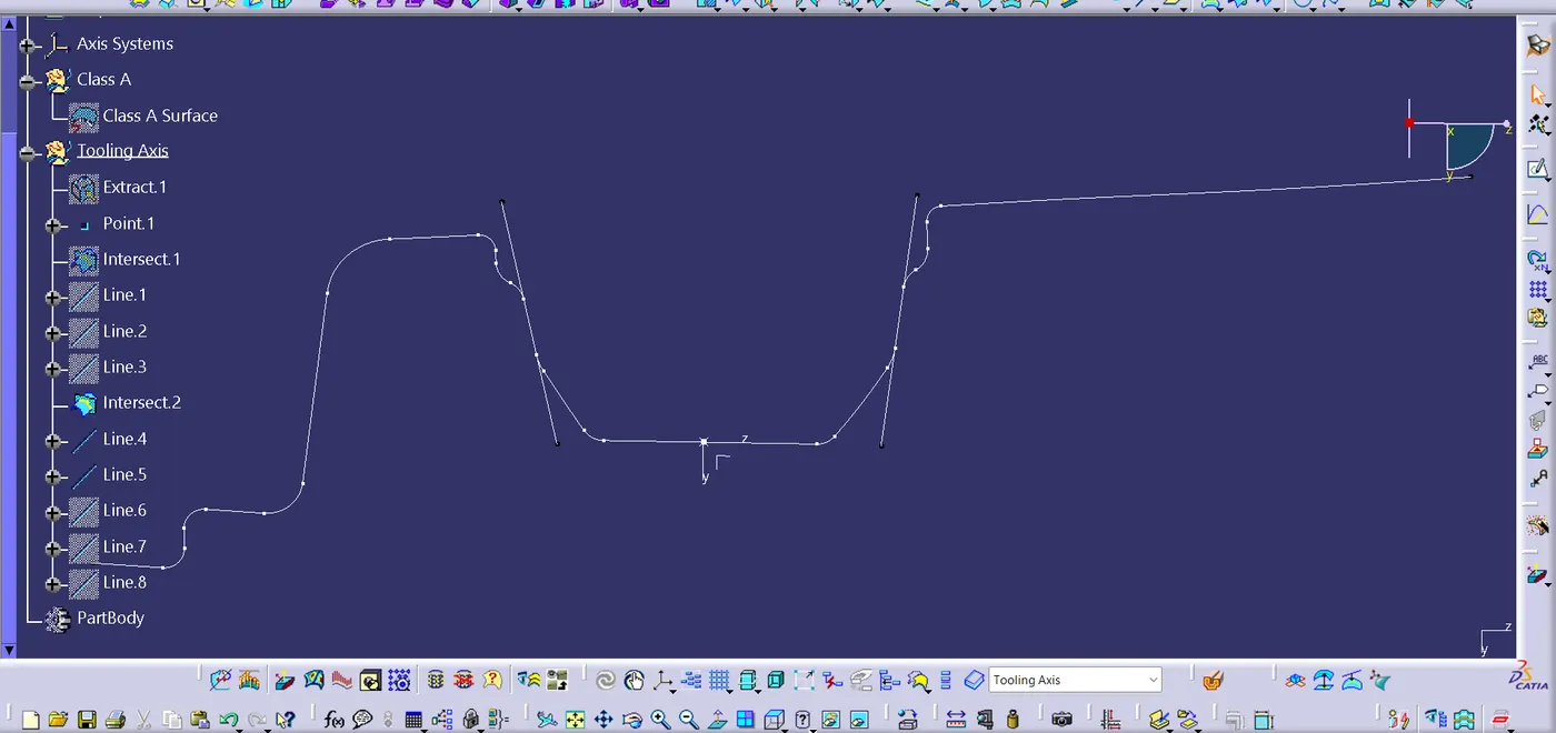
- Insert an axis system at a point and take the intersection along XZ and YZ direction, then draw the lines to bisect for forming the axis in both direction.
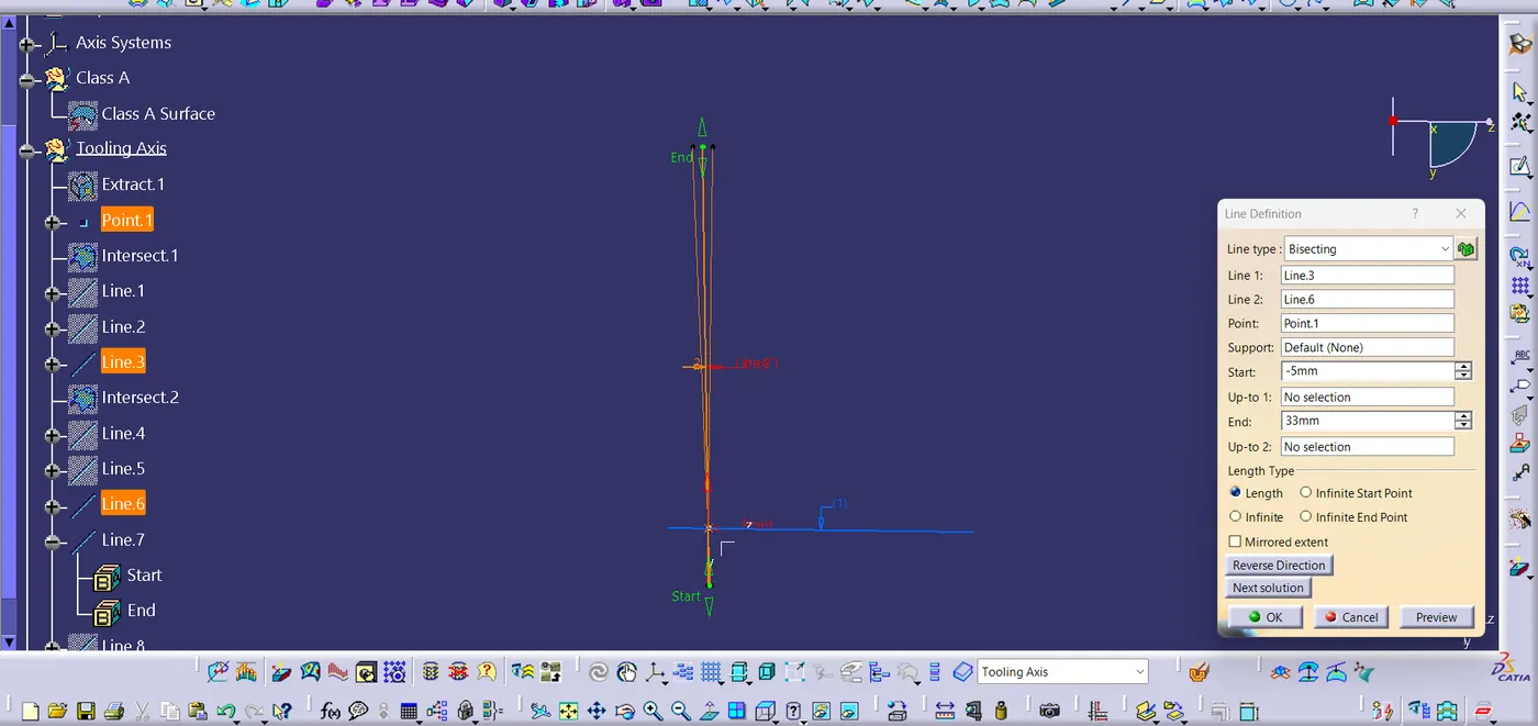
- Then bisect both lines to get main tooling axis.
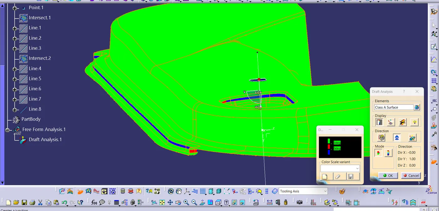
- Then perform the draft analysis to check the surface is clearing the darft through tooling axis.
- If not check for other tooling axis and still not clearing then request for design change.
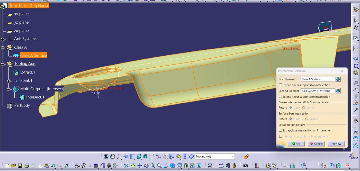
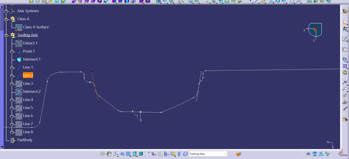
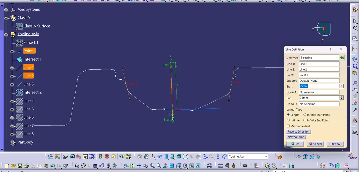
By taking the intersection itself it is clear that two sides won't be clearing the draft since they and inclined inward.So request for class A design change at those areas.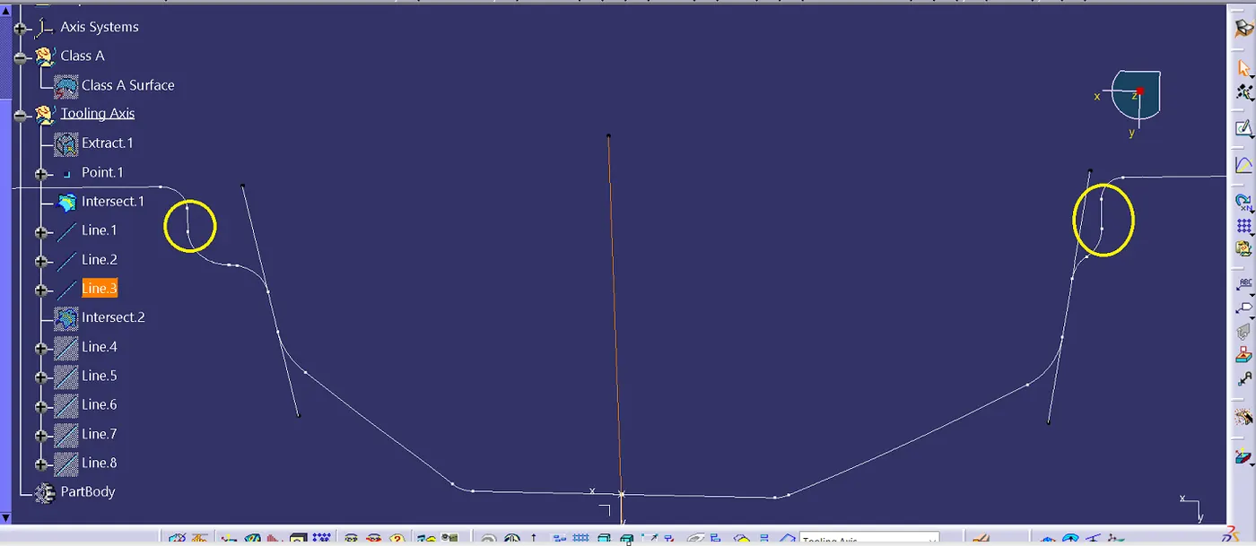
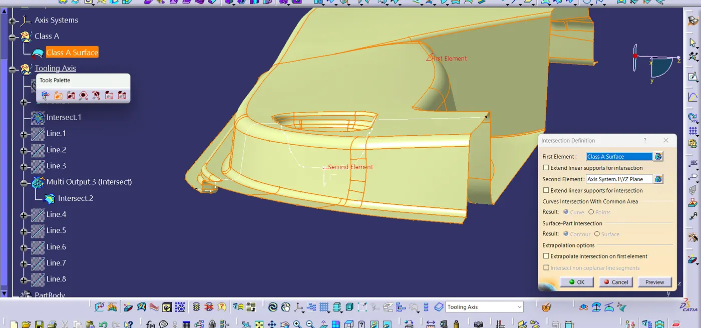
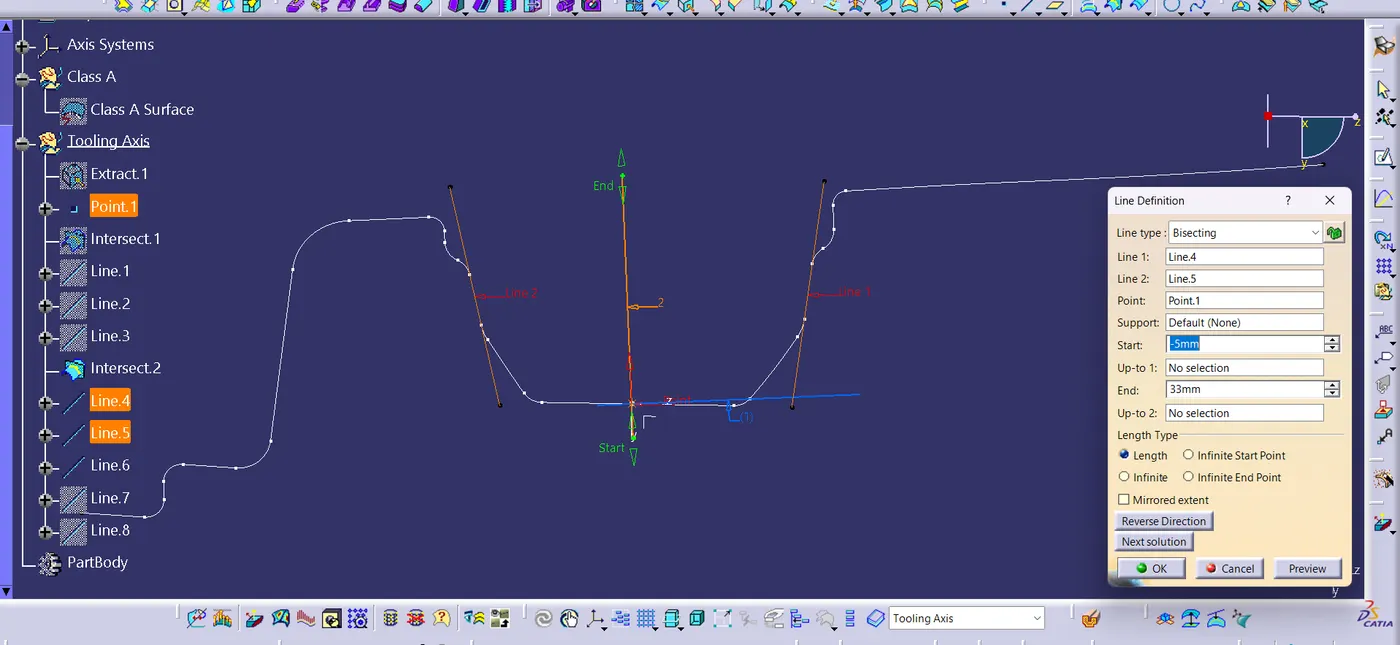
Here also it is clear that two sides won't be clearing the draft since they and inclined inward.So request for class A design change at those areas.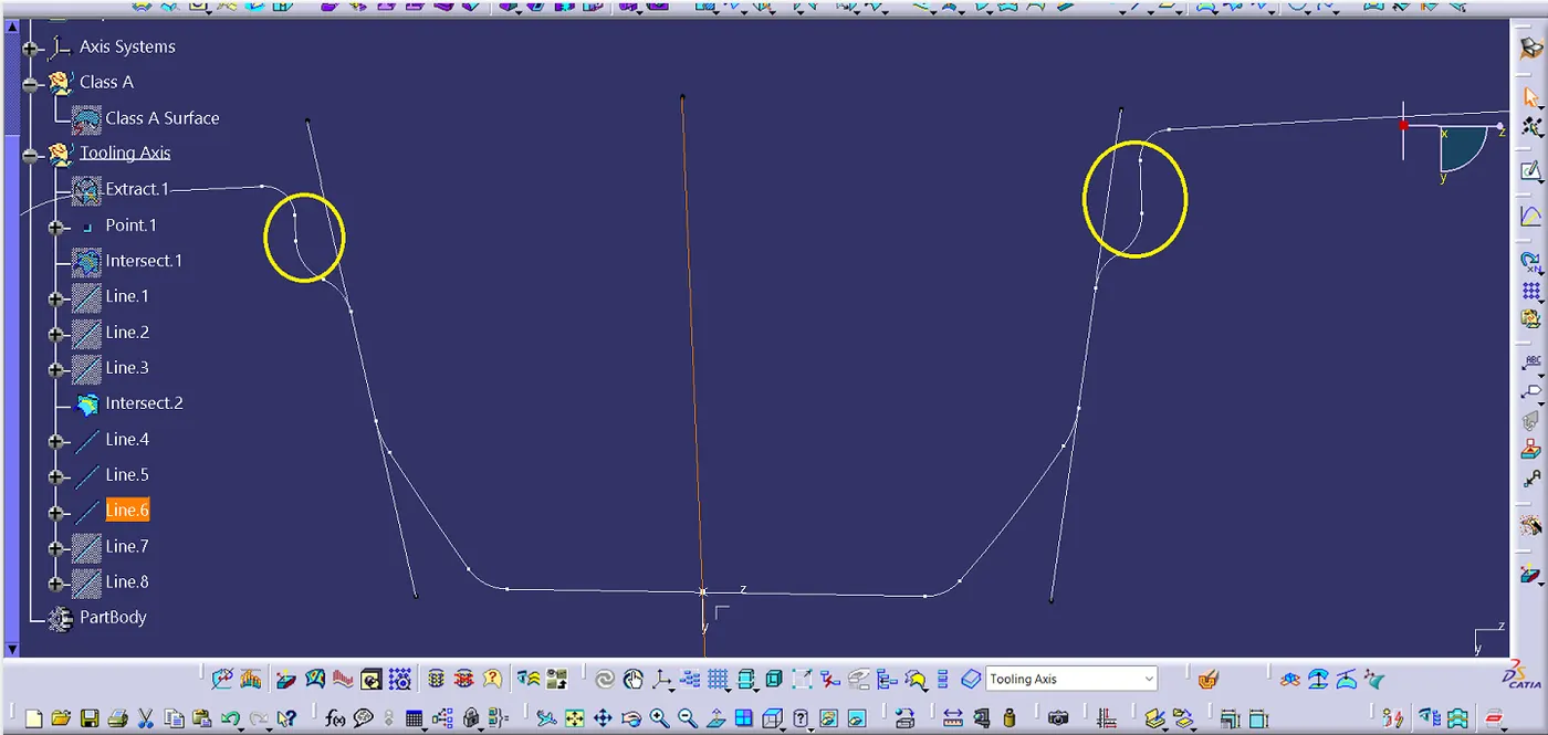
Bisecting both lines created to get the main tooling axis
Draft analysis
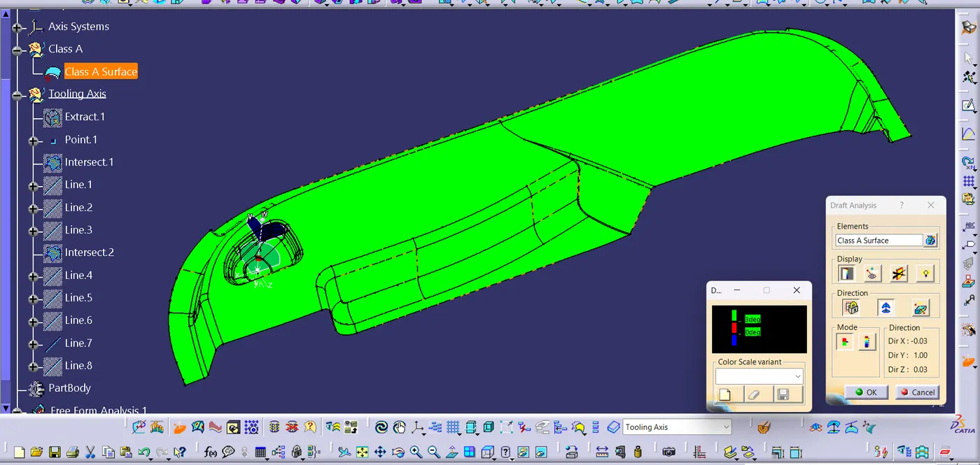
In the first look it seems to be fine and clearing all the areas but in the detailed inspection, as predicted there were surfaces that dosen't clear the draft.
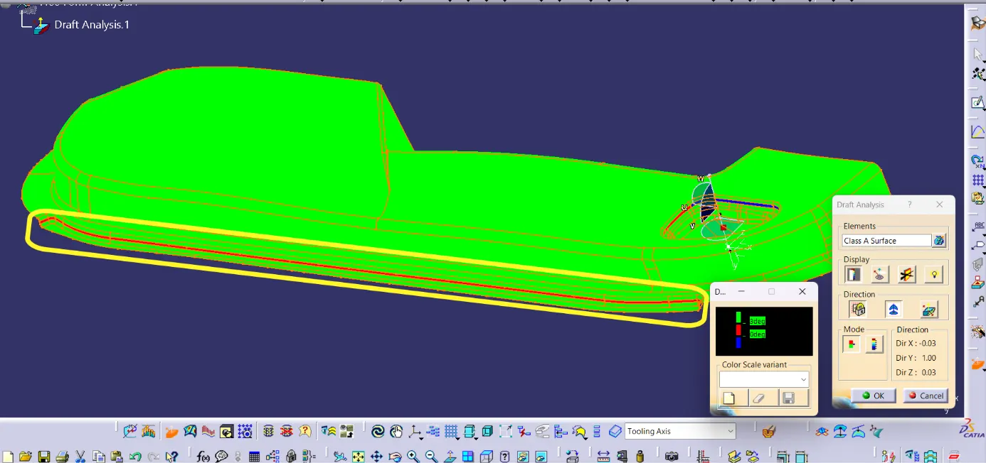
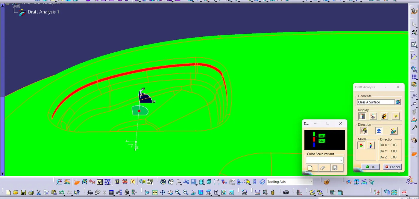
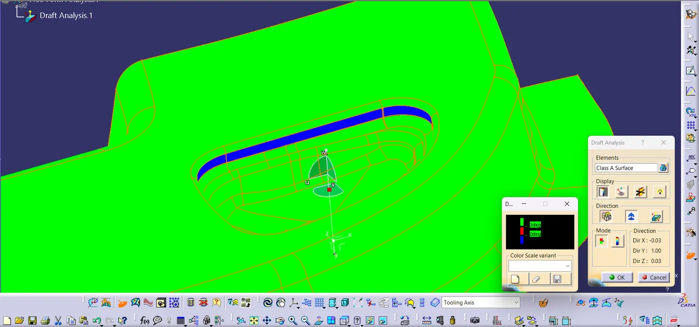
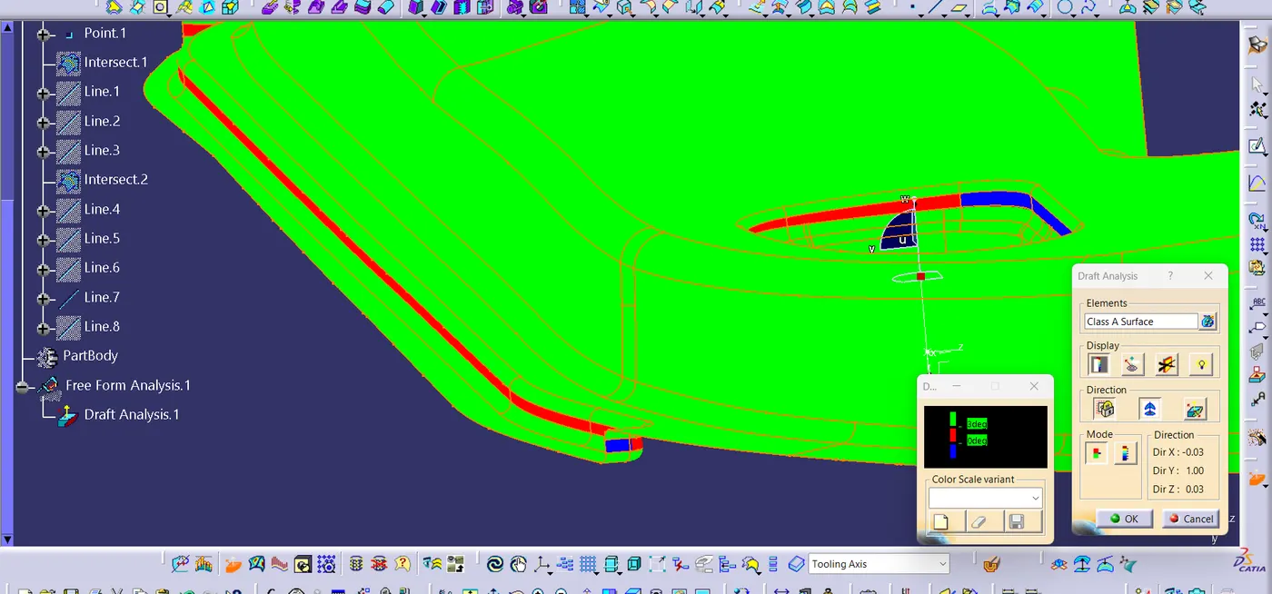
I have checked for another tooling axis which is perpendicular to the base surface but the results were identical, so i decided to go with the first tooling axis which will the be Main tooling axis.
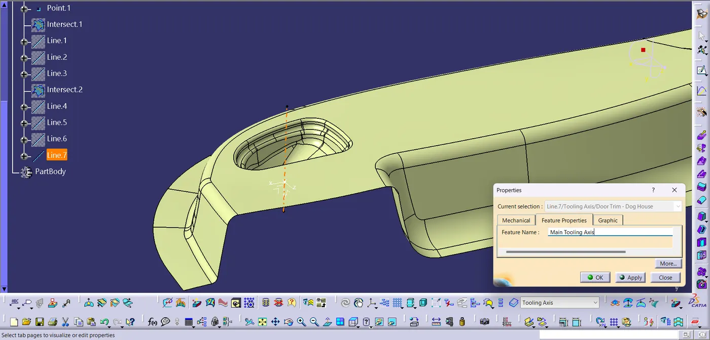
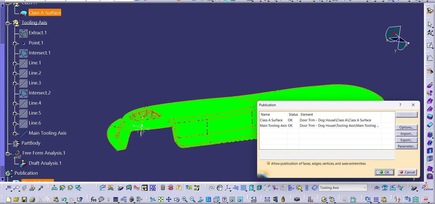
Published Class A surface and Main tooling axis
Step 2 : Creating Class B Surface.
- Insert a Geometrical set for Class B surface.
- Using 'Offset' command offset the class A surface along the B surface side 2.5 mm which is the thickness of the part.
- Check for missing surfaces and clear them if any.
- Check again using boundry command to make sure there is no gaps left.
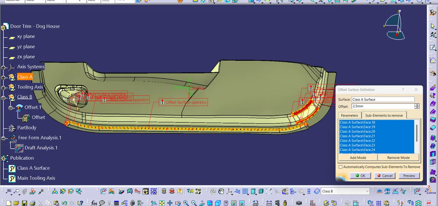
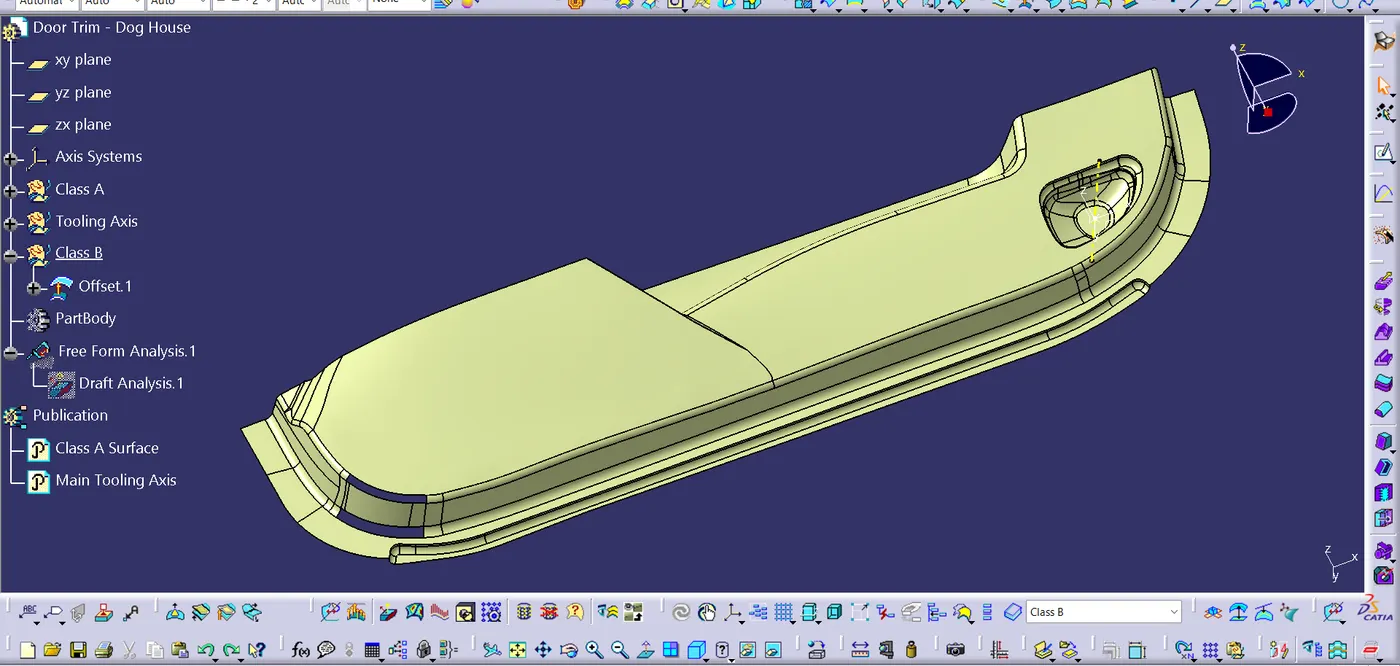
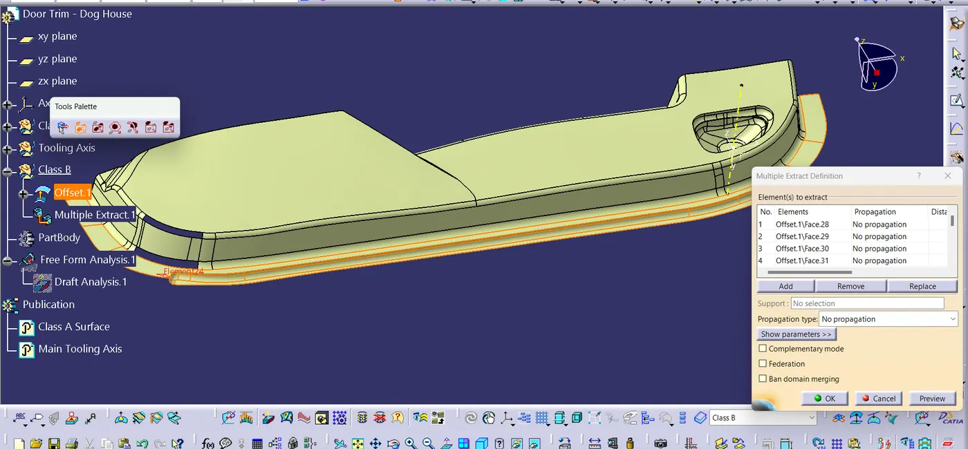
- Inorder to fill the area the two surfaces are extracted using multiple extract command
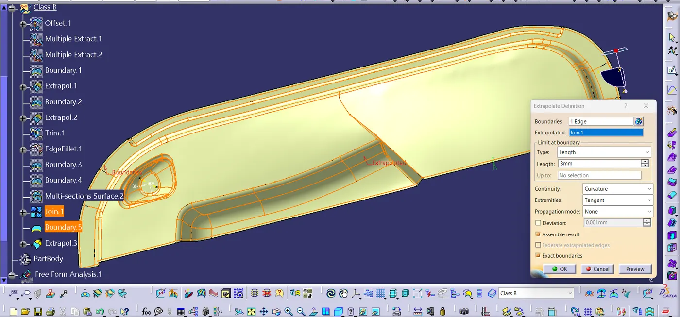
- Then they were extrapolated at the boundries side where the fillets were missing
- Then the extrapolated surfaces were trimed together using Trim command
- Then the fillet were given which is 7 mm
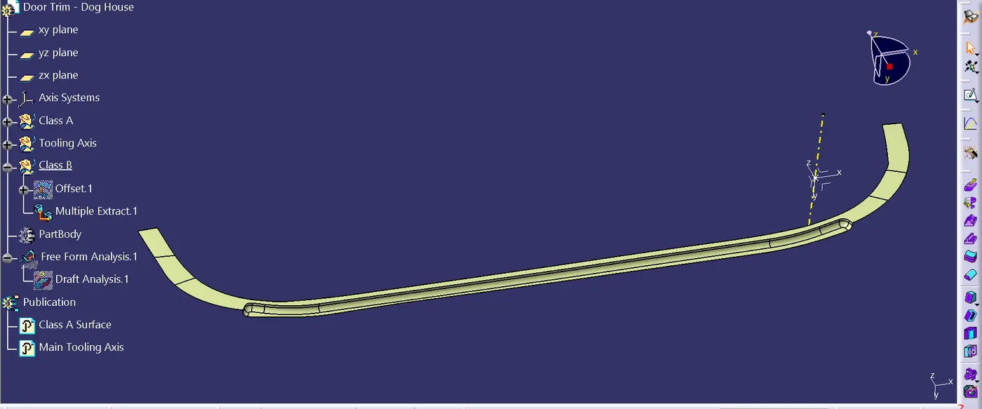
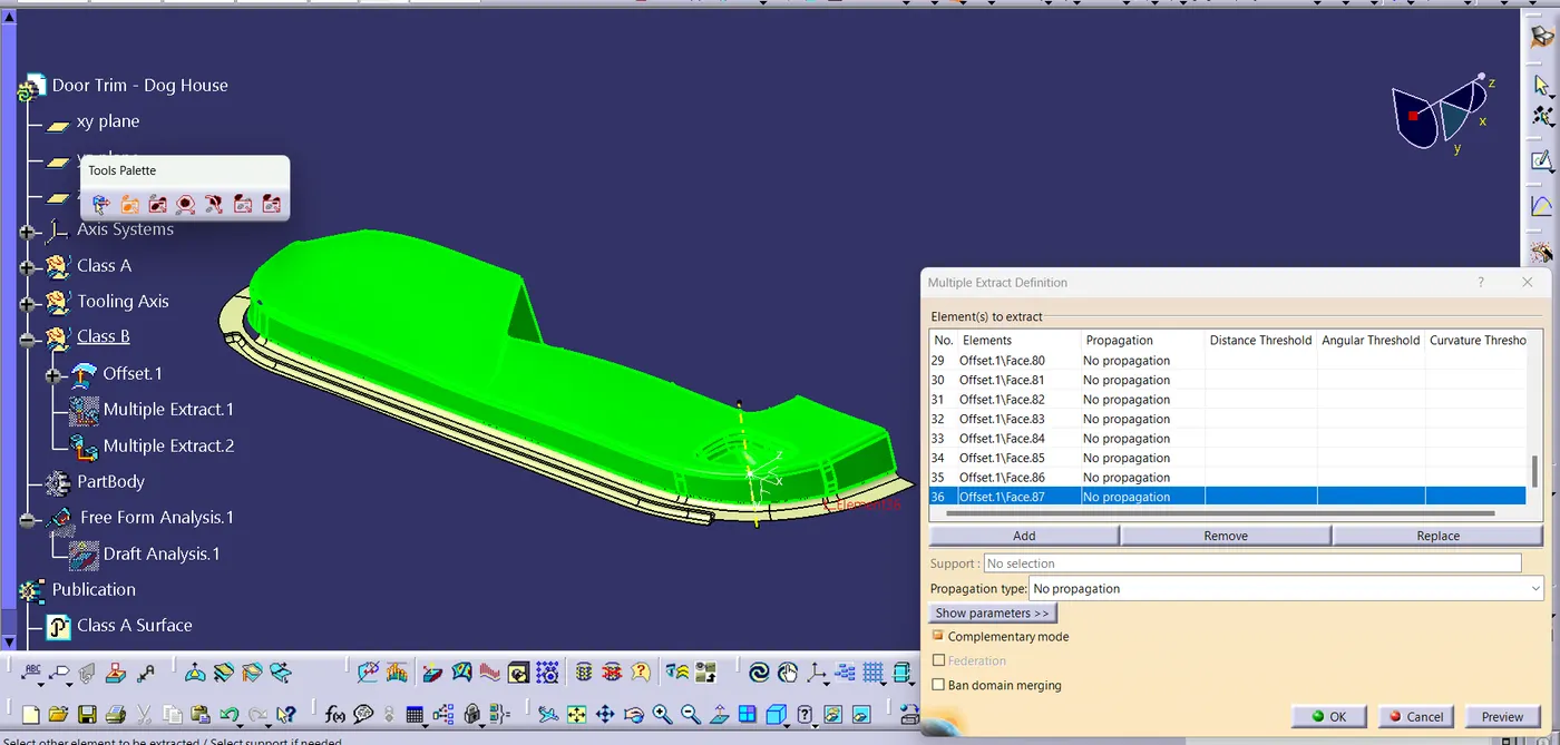
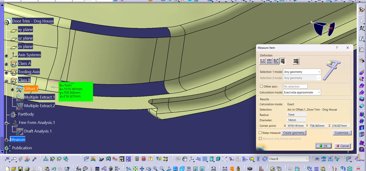
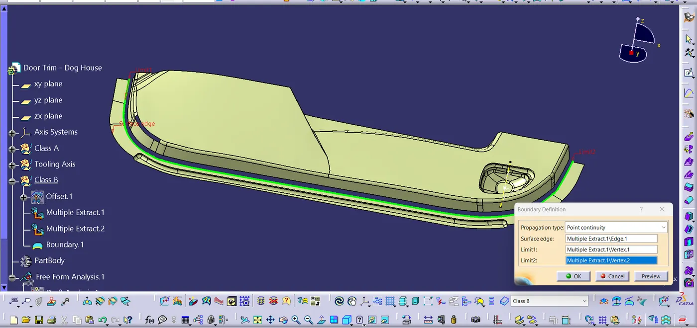
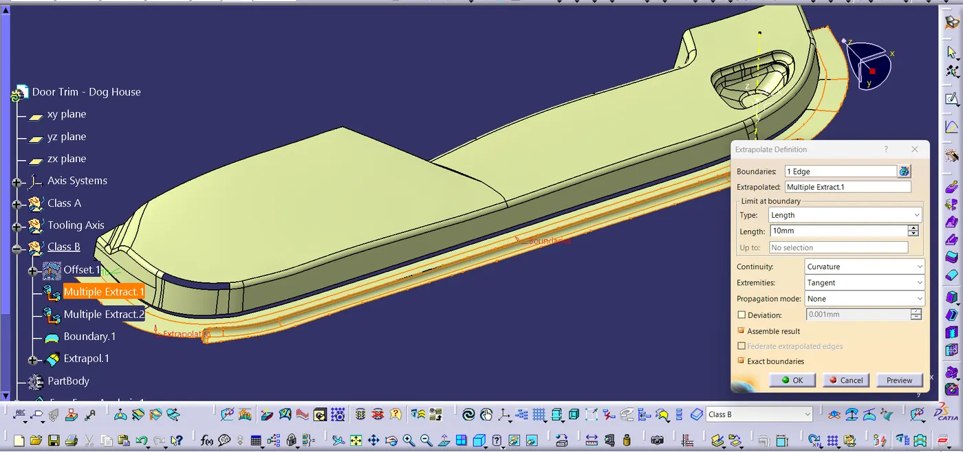
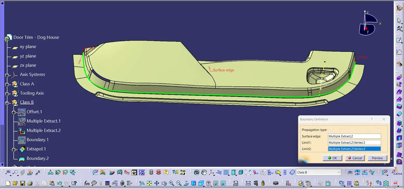
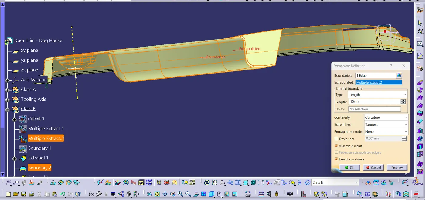
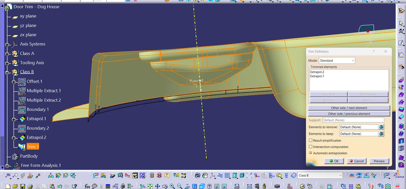
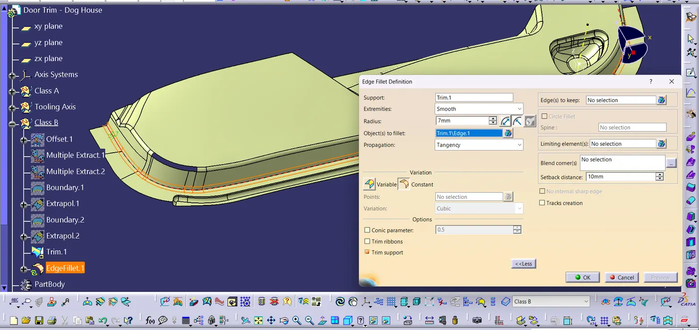
To make the other missing surface here we use the 'Multi-Sections Surface' Command
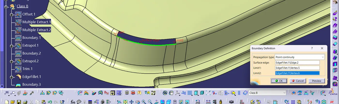
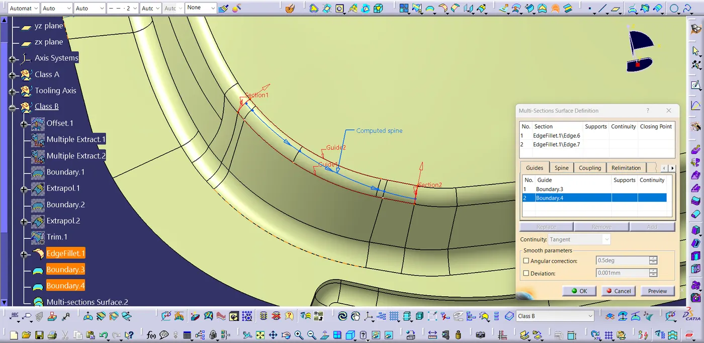
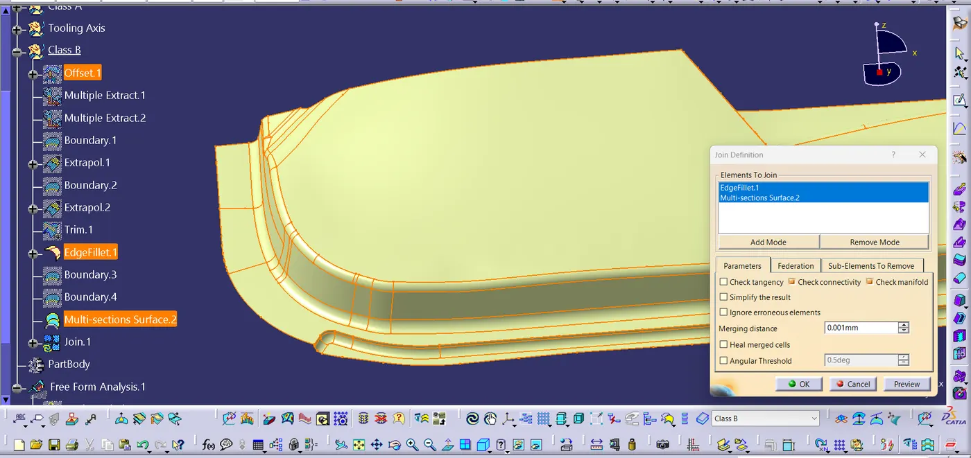
- Check for continuitity and open boundry
- Then extrapolate for few length so as to make intersection when Class C surface is created.
- Publish Class B surface
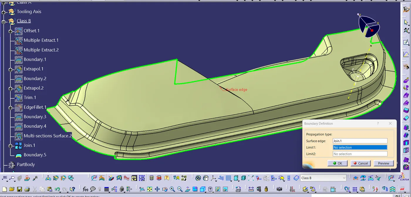
Step 3 : Creating Class C surface
- Insert geometrical set for class C surface.
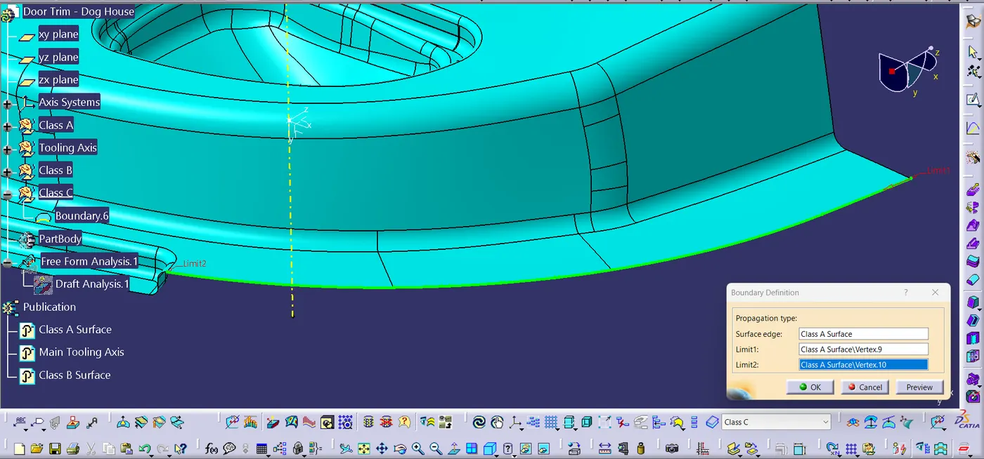
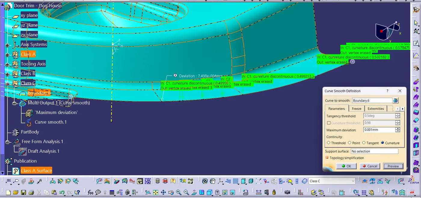
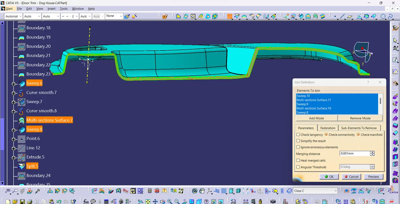
- Create the boundry of the Class A surface and using 'Sweep' command make the class C surface with a draft angle of 3 degree with the main tooling axis.
- A single boundry and sweep won't give the required Class C surface here we have to make multiple boundry and then using 'Sweep' and 'Multi-Surface Surface' command to make C surface
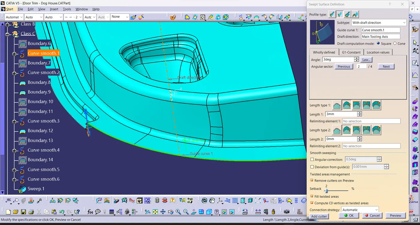
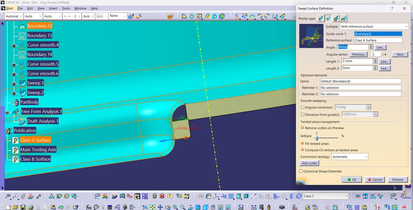
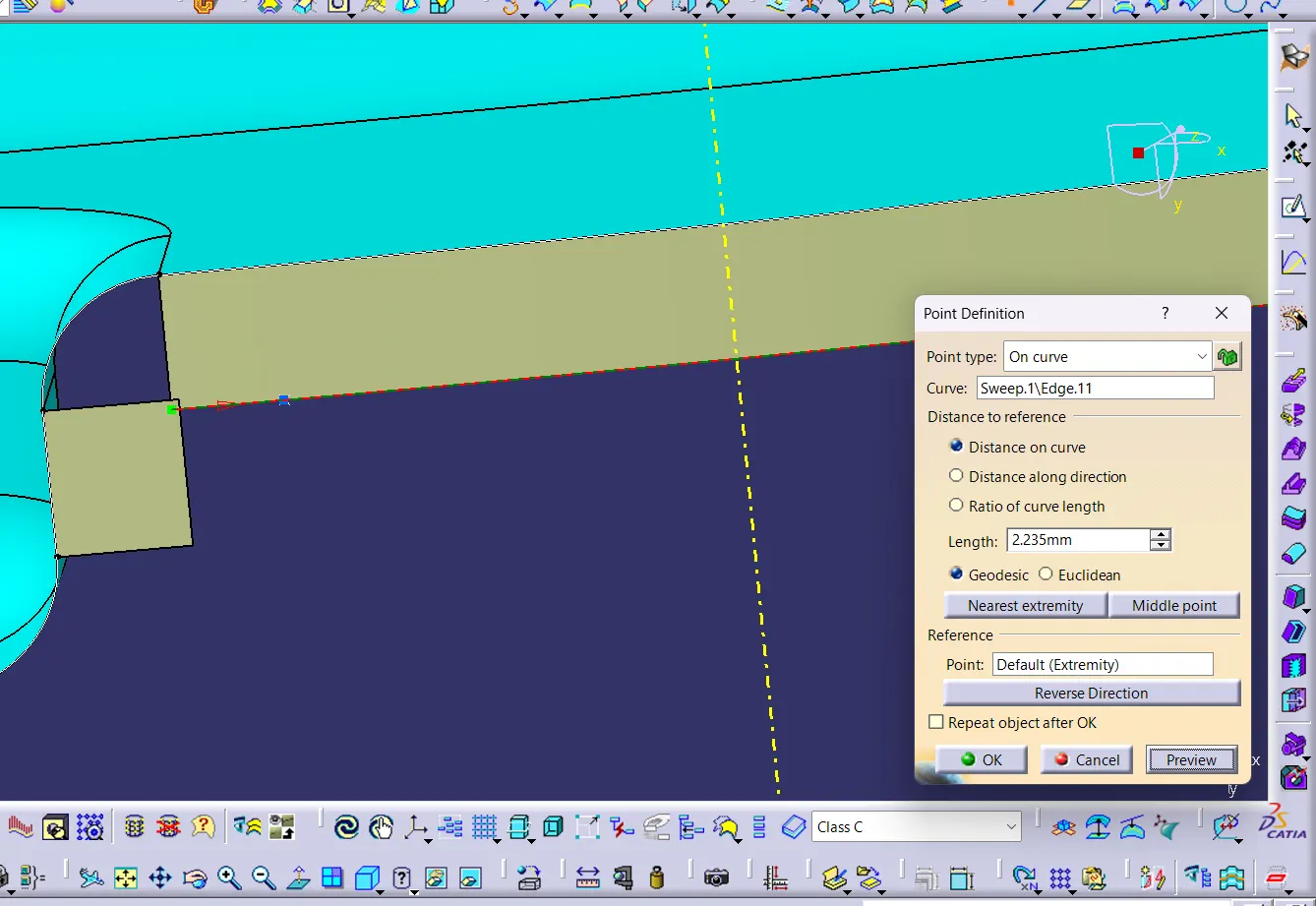
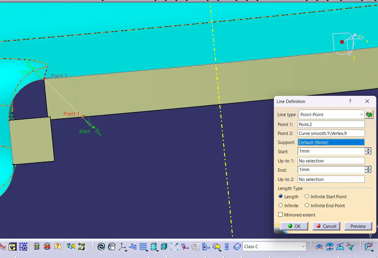
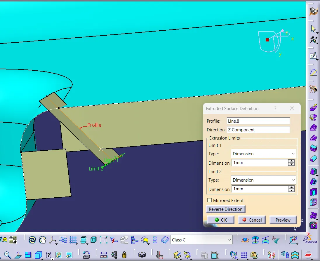
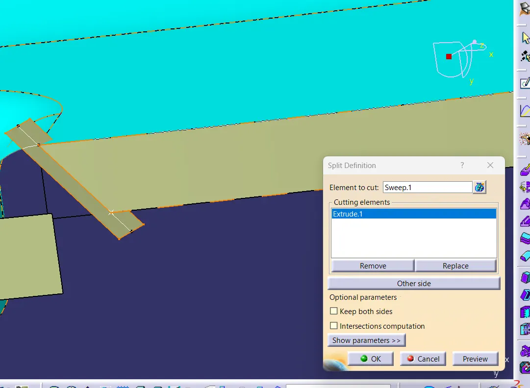
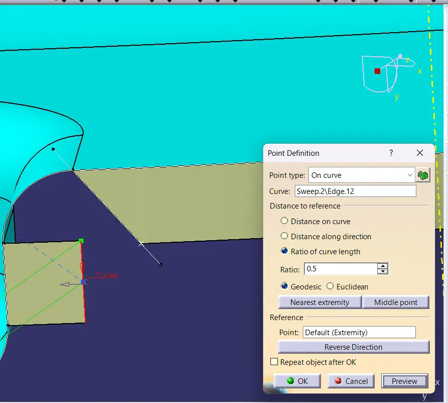
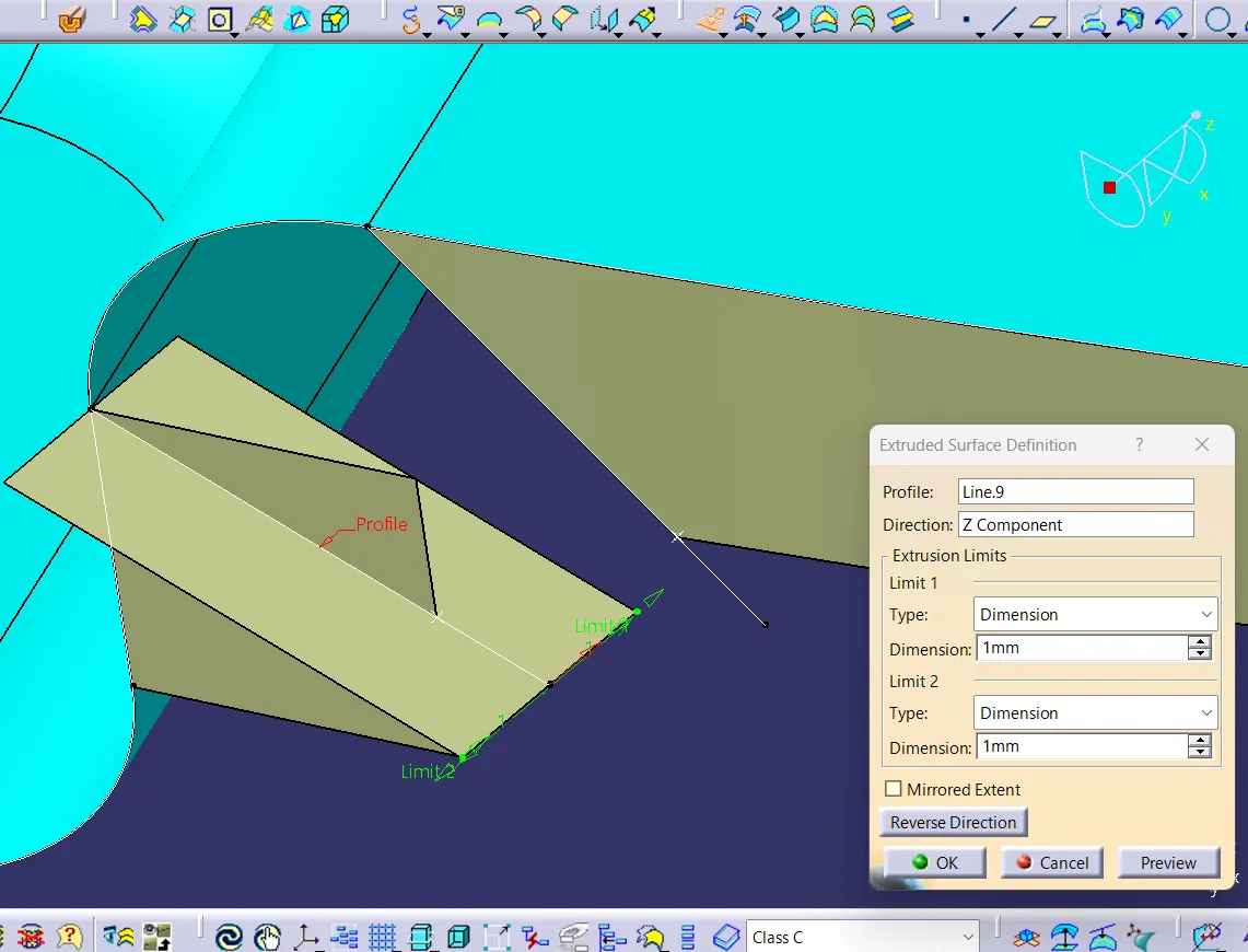
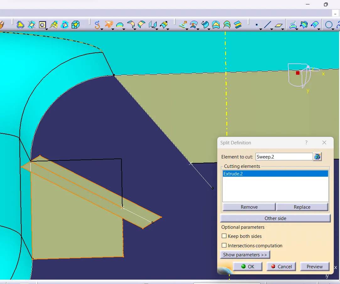
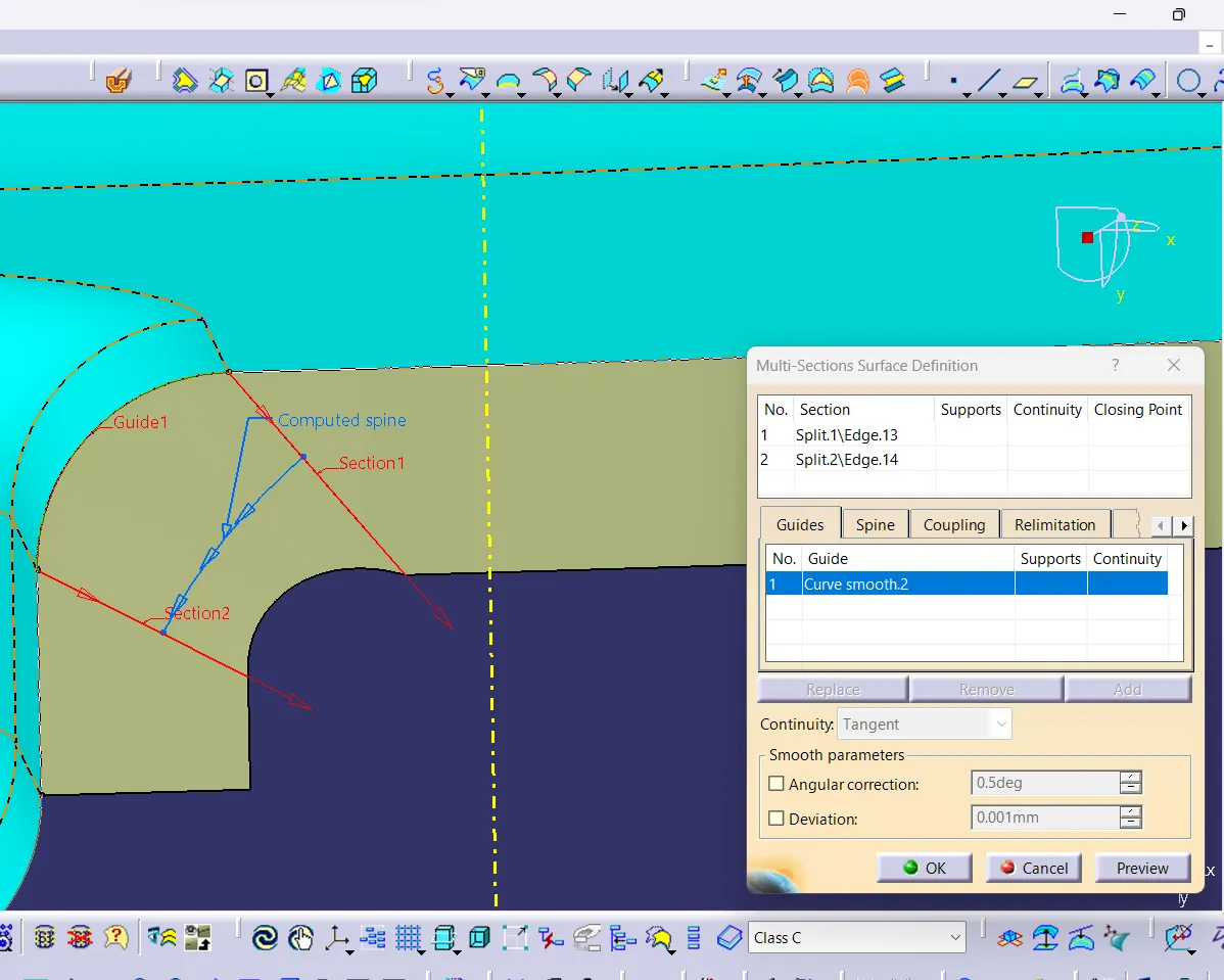
Now the Class B is bisecting Class C perfectly
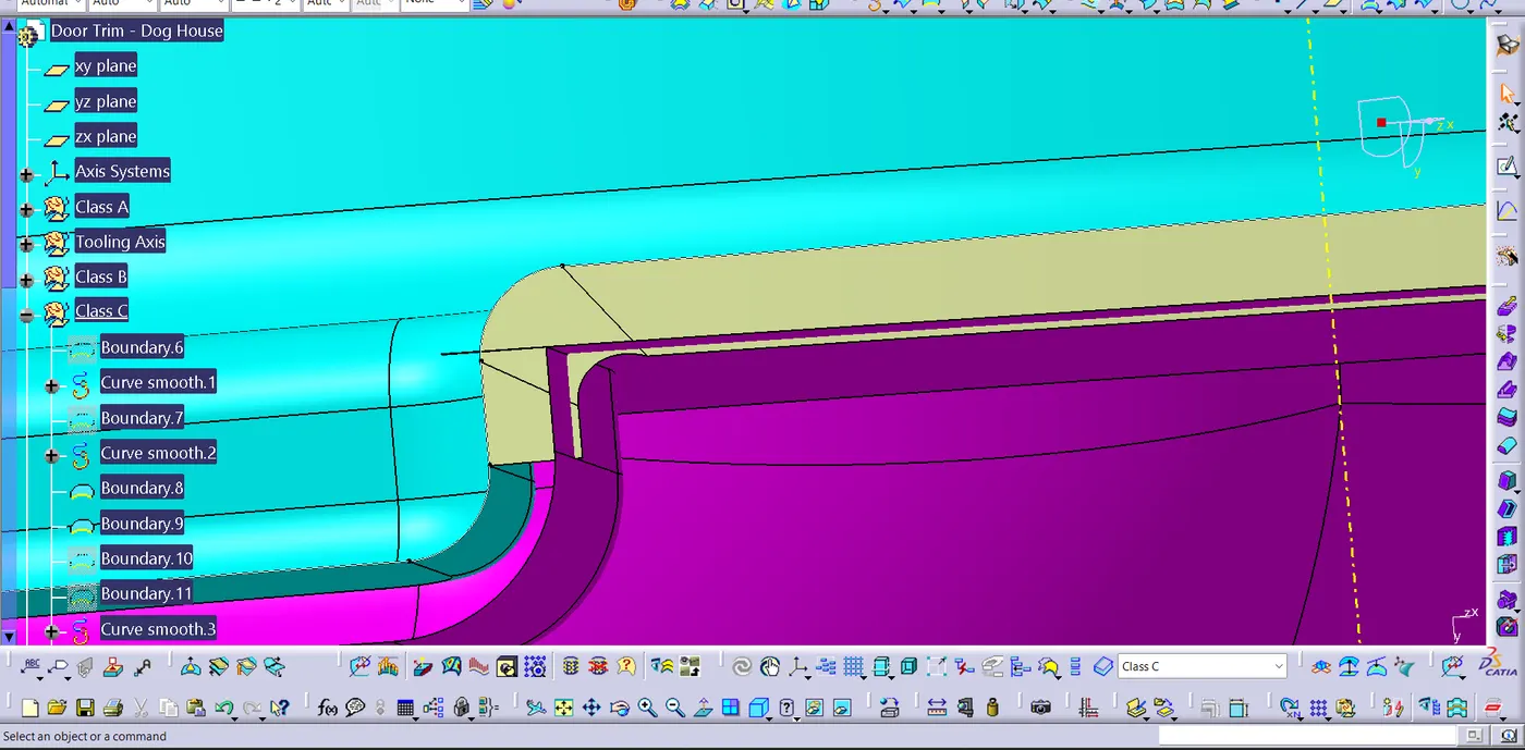
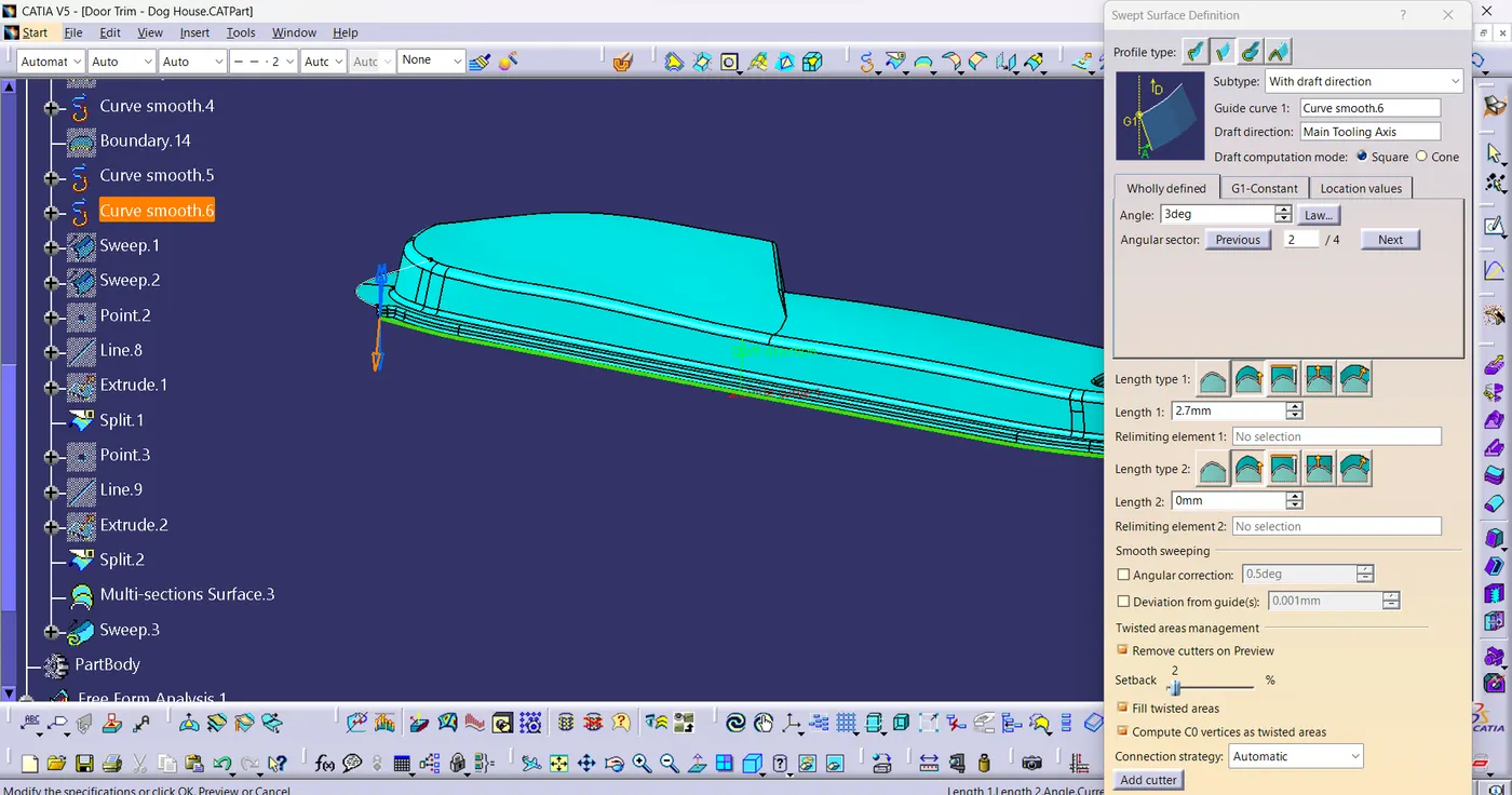
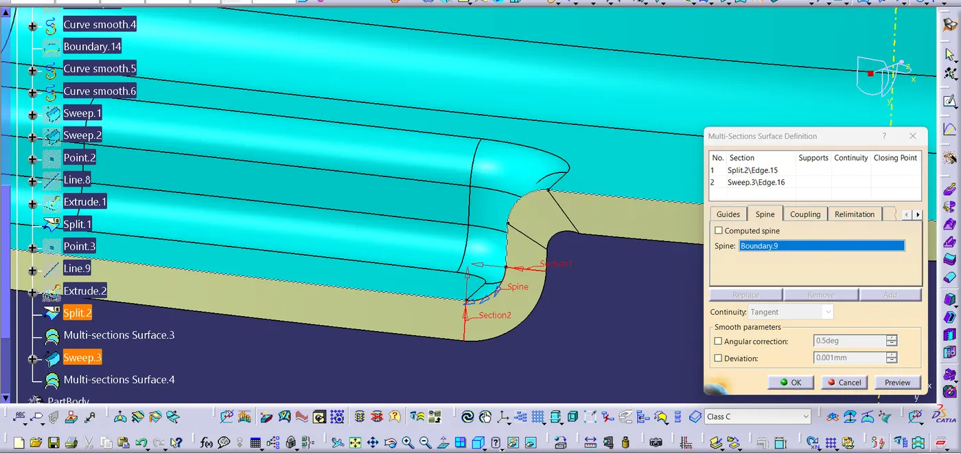
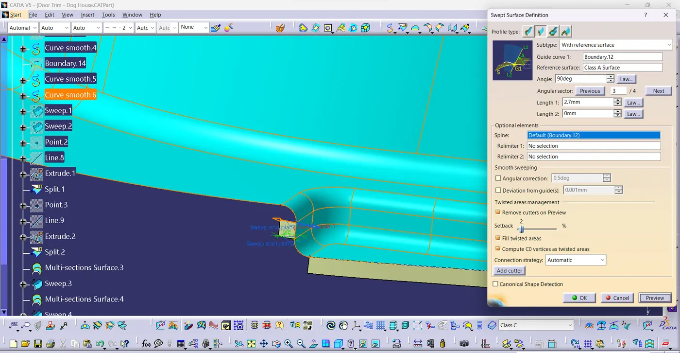
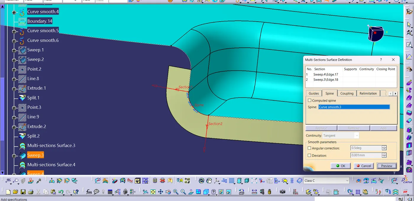
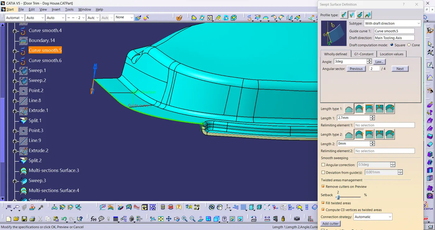
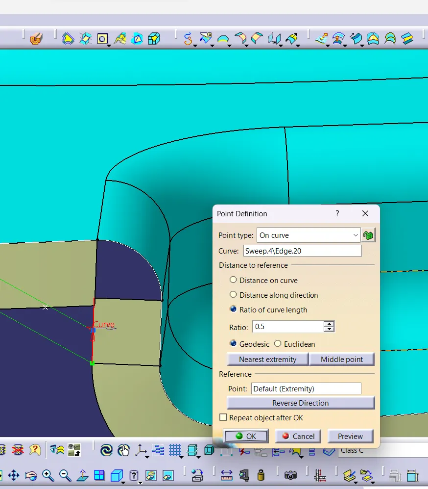
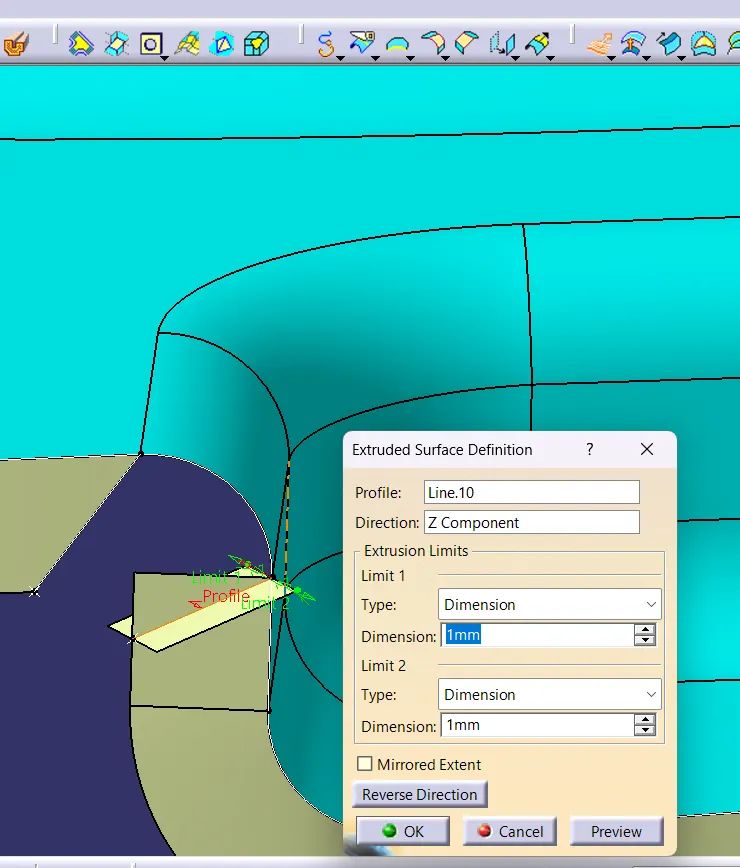
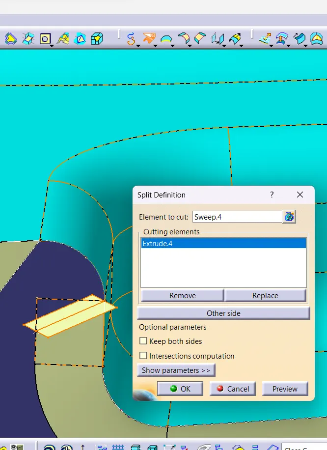
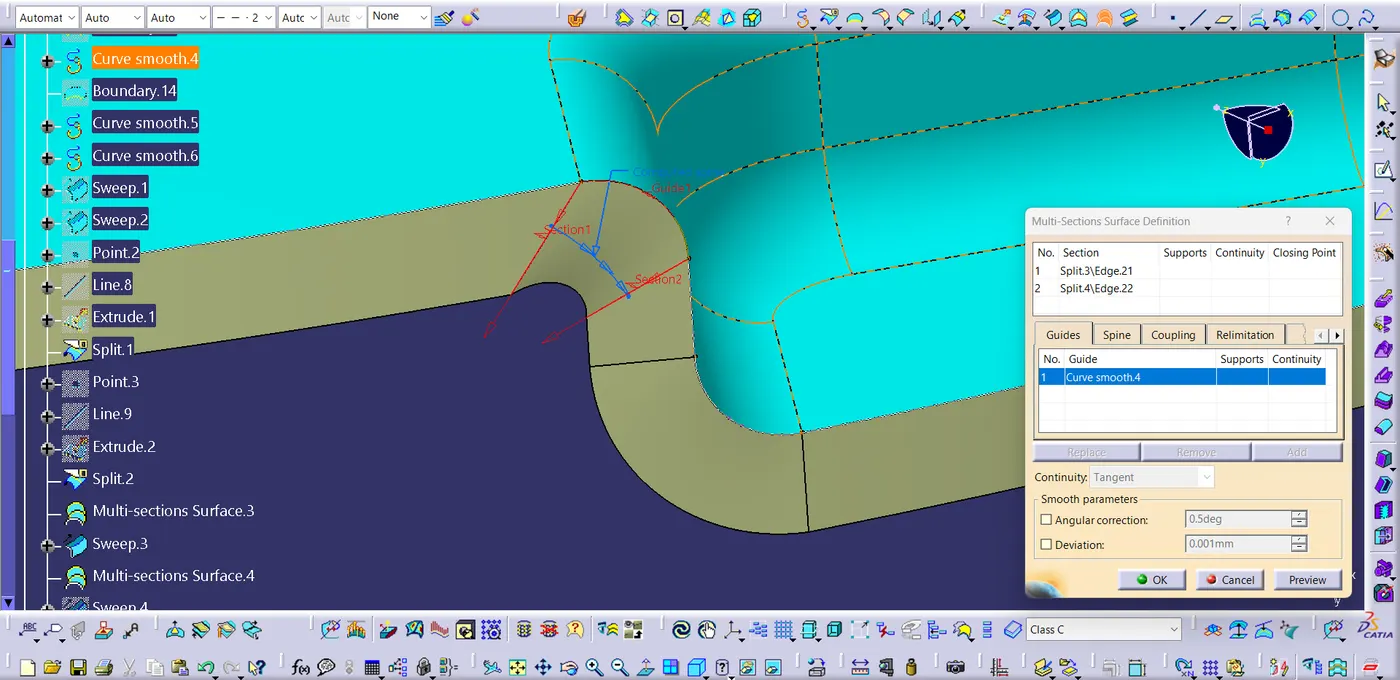
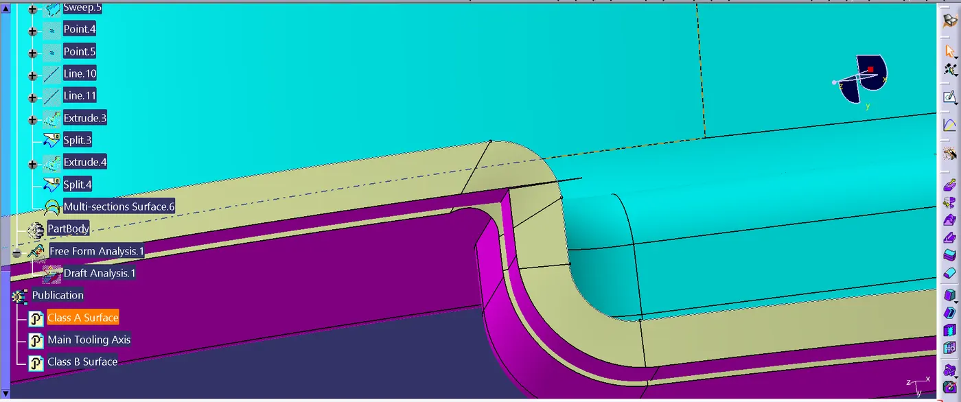
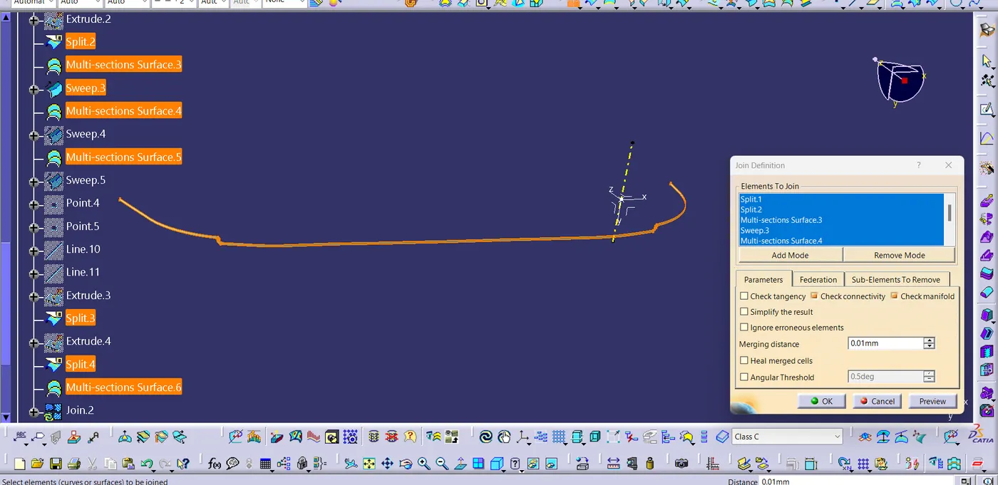
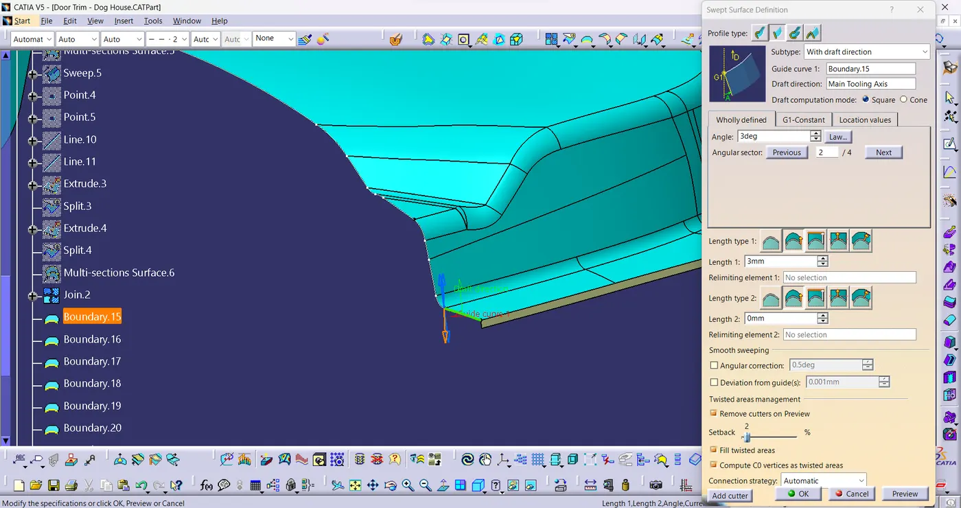
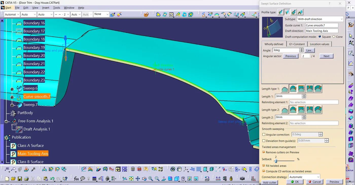
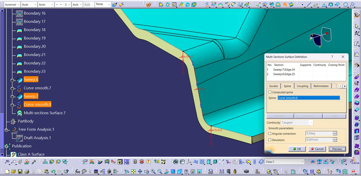
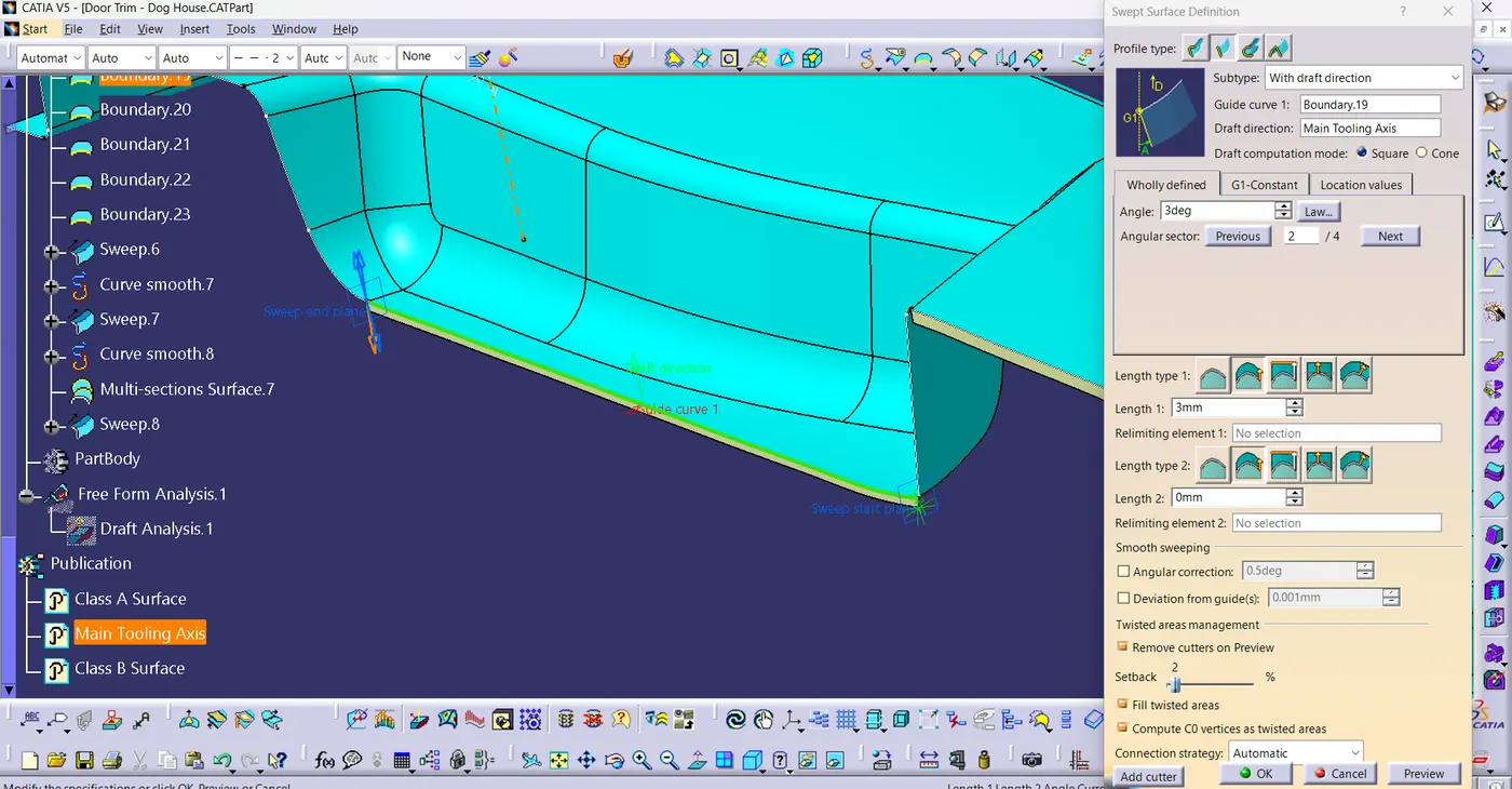
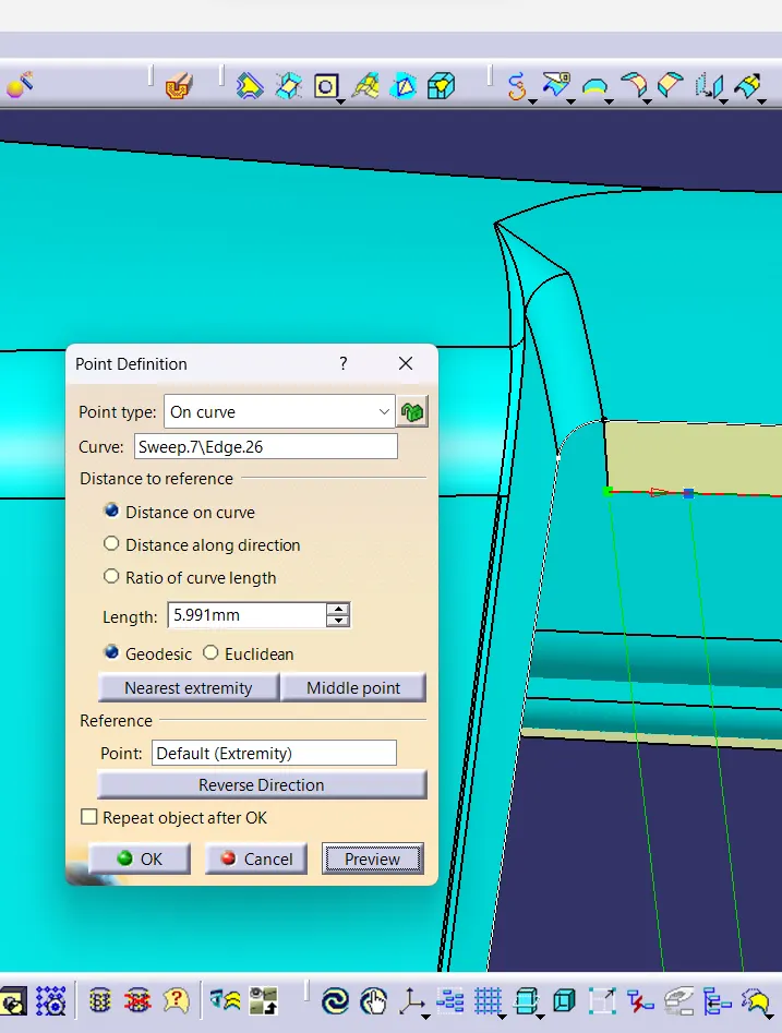
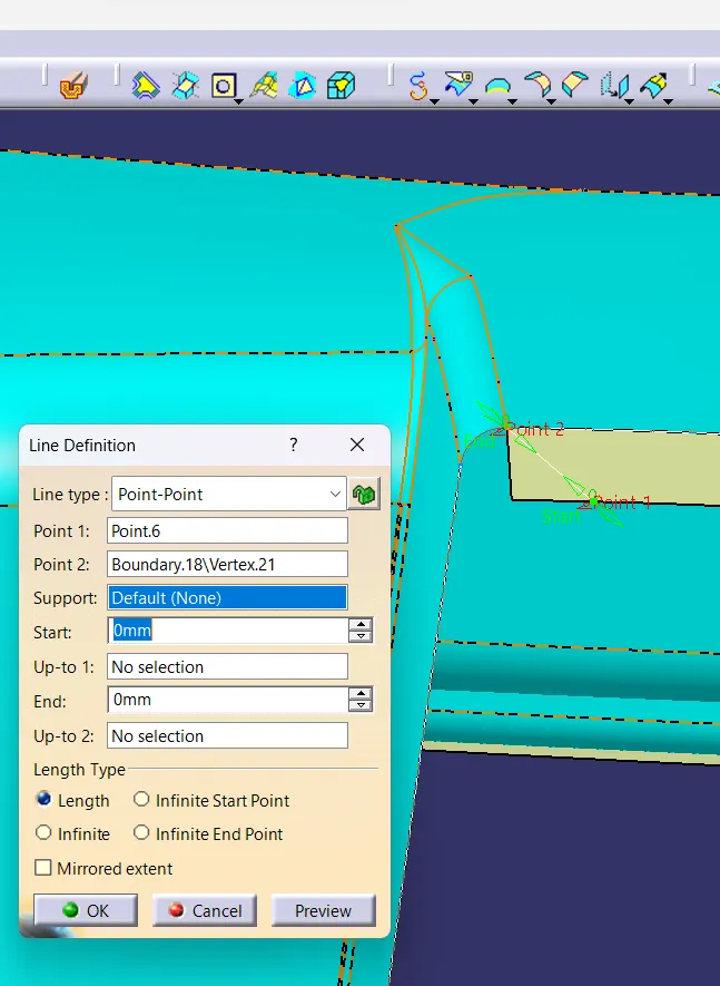
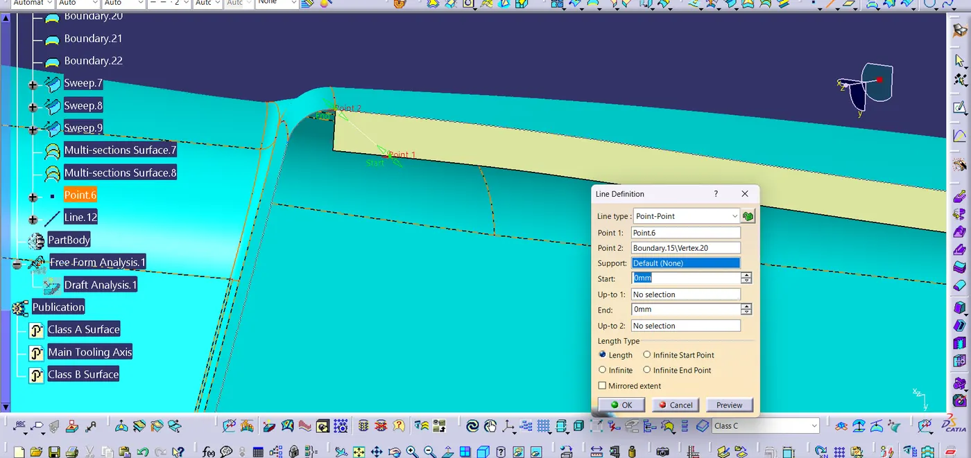
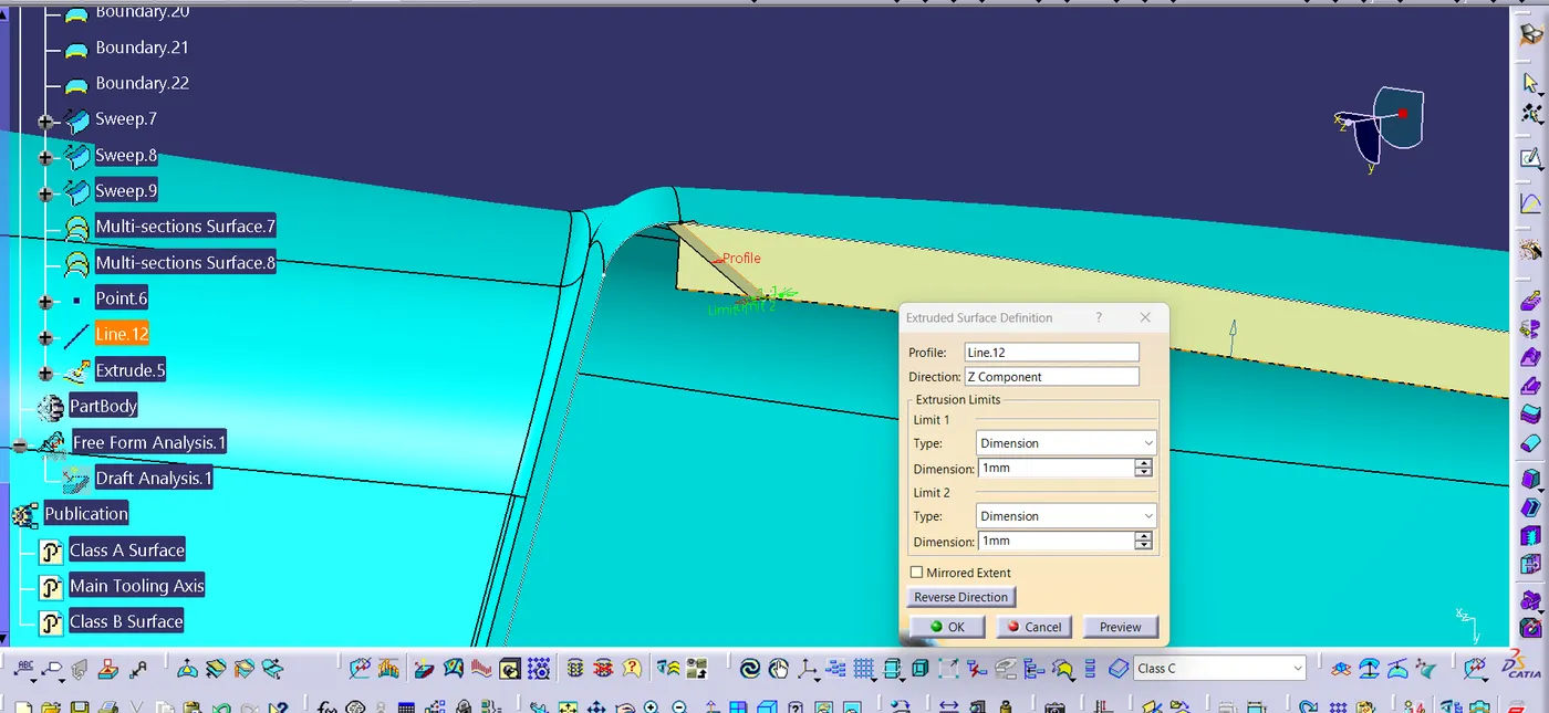
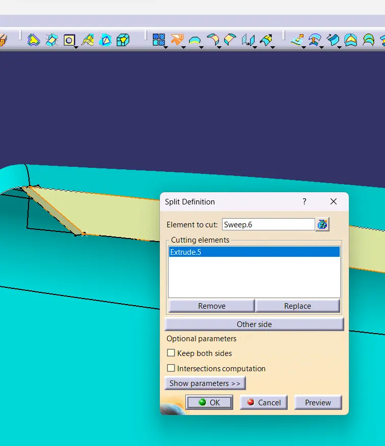
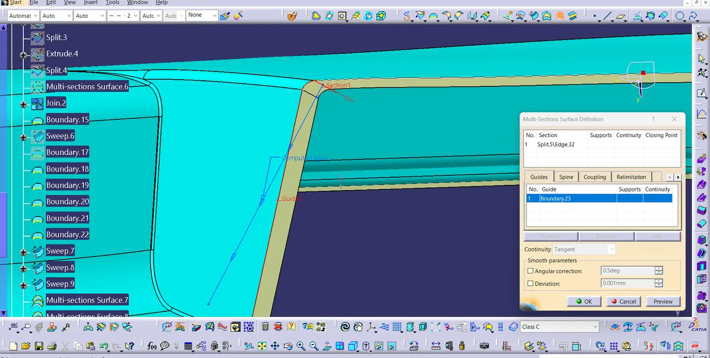
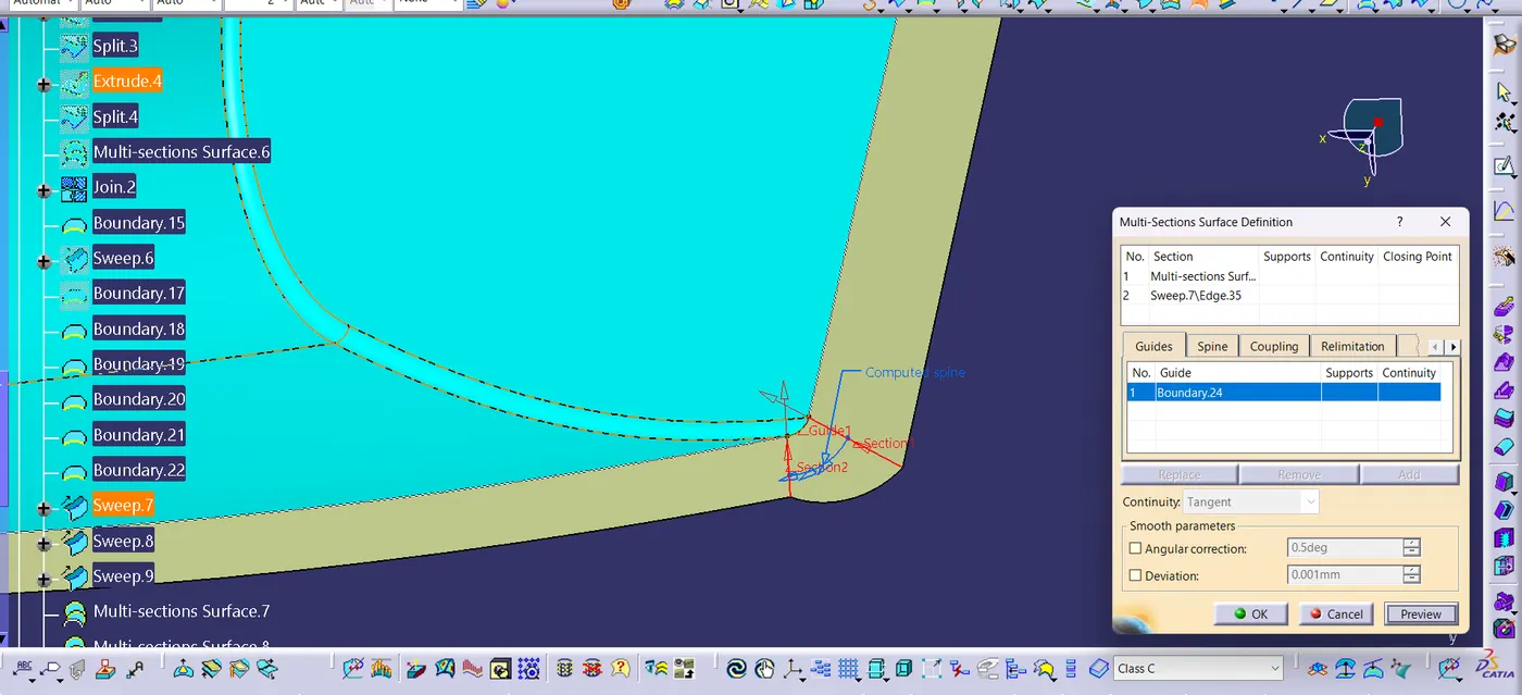
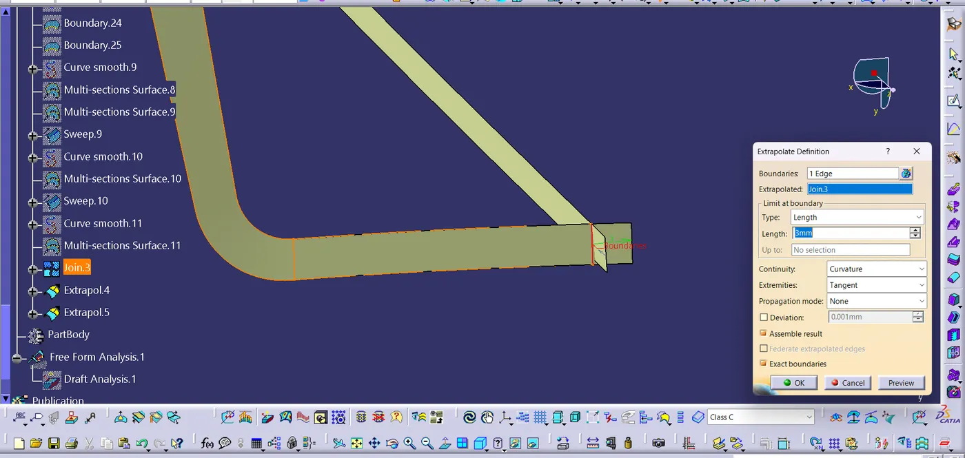
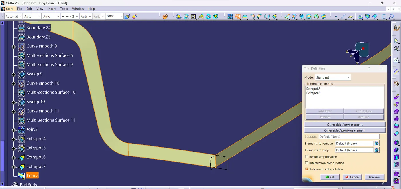
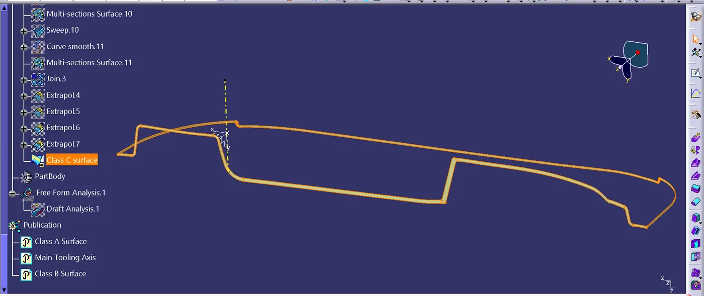
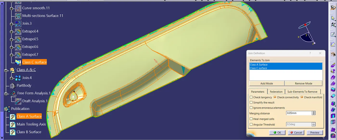
- Join the differents surfaces using join command and them trim them together by extrapolatin to get the final Class C surface.
Step 4 : Make the closed surface
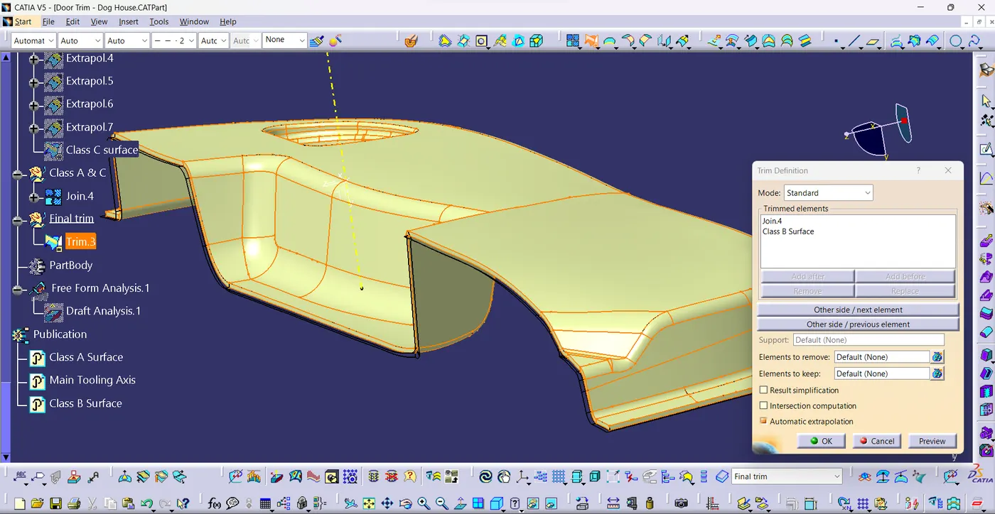
- Join Class A & Class C together and then trim it with Class B to form the closed surface.
Step 5 : Converting Closed surface into Solid part.
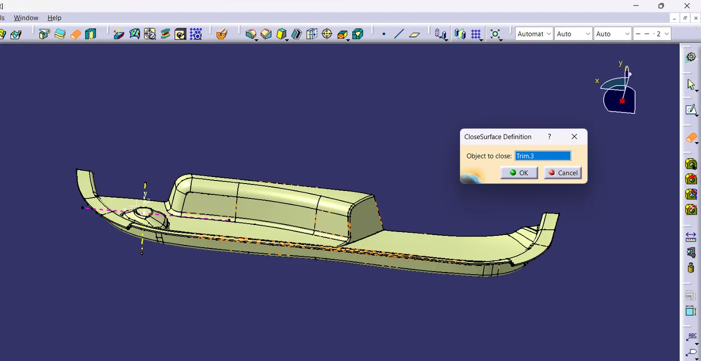
- Switch to part design workbench and insert a new body, then using 'close surface' command convert the closed surface to solid part.
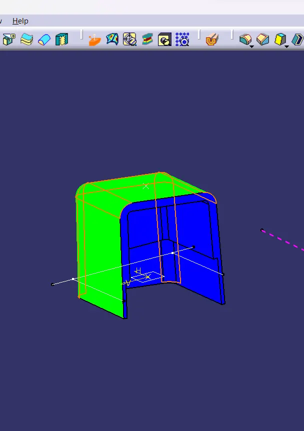
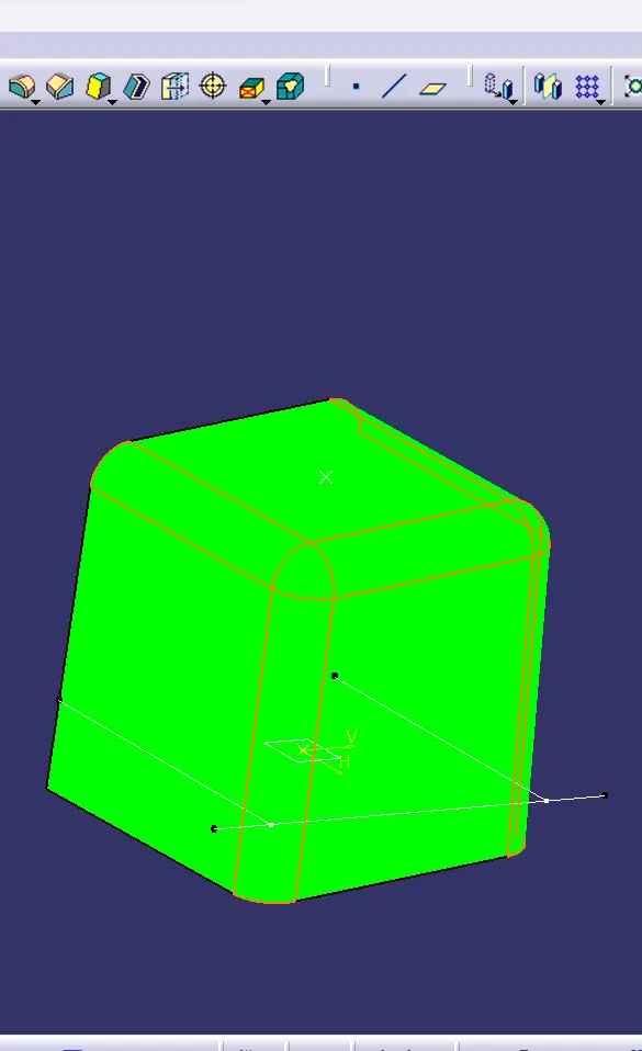
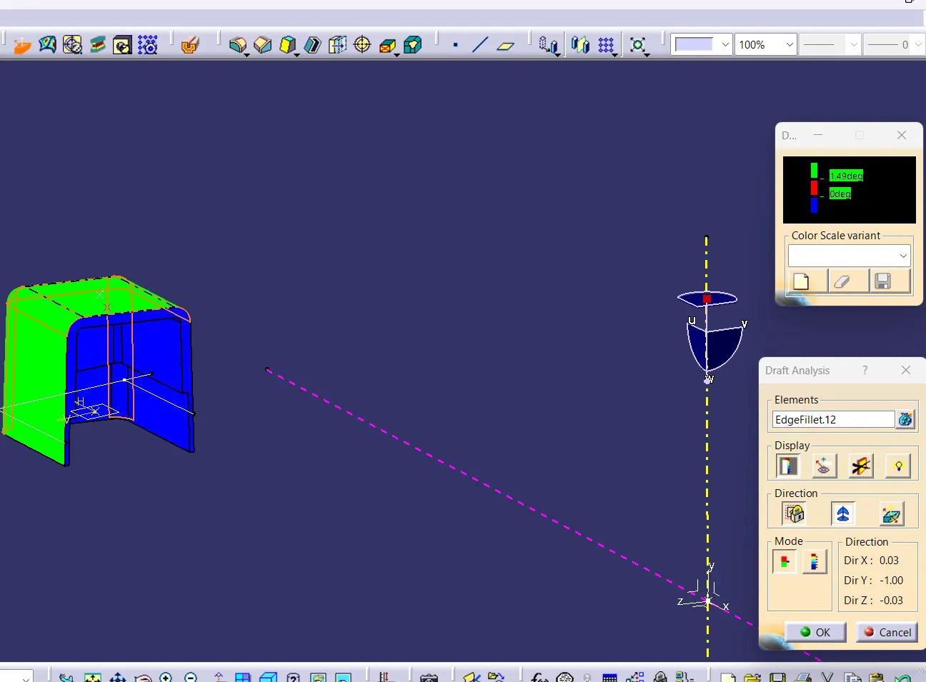
- After converting to solid part draft analysis is carried out
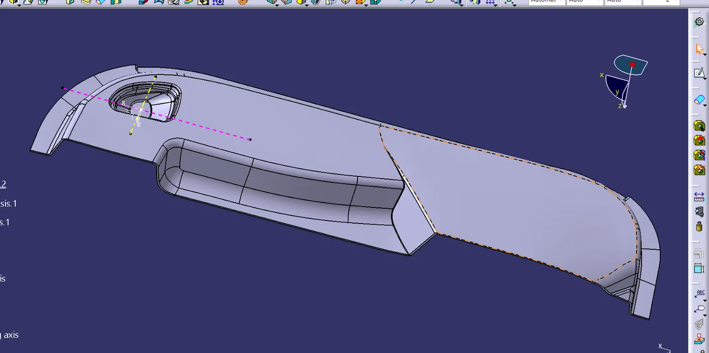
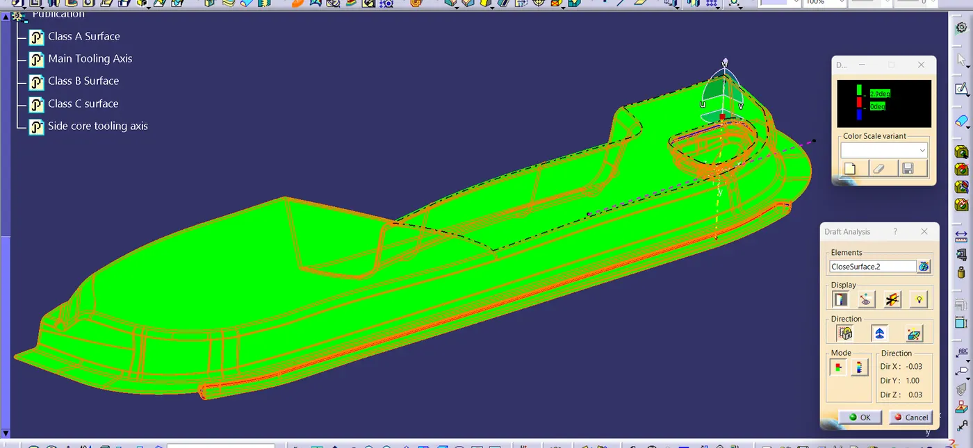
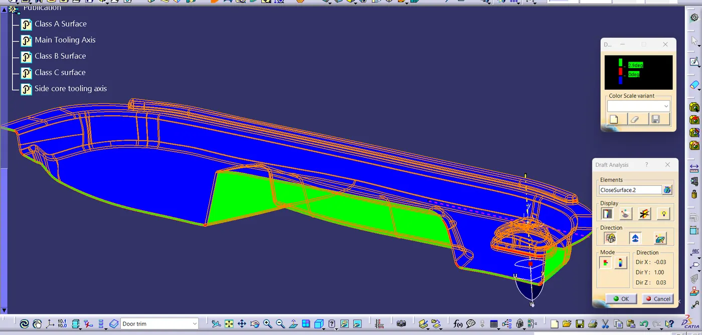
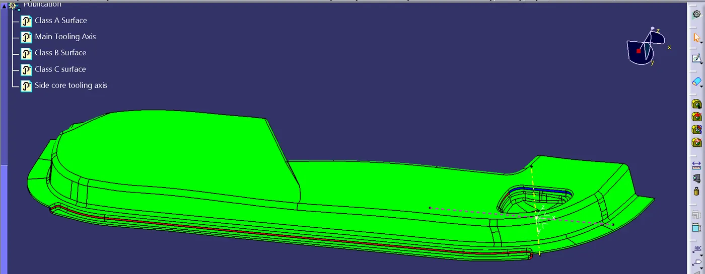
- From the draft analysis it is clear that all the class A surface and most of all the edges are clearing the draft.
- At the same time we can also see some of the areas are not clearing the draft which we saw when draft analysis was done for class A surface
Step 6 : Creating Dog House
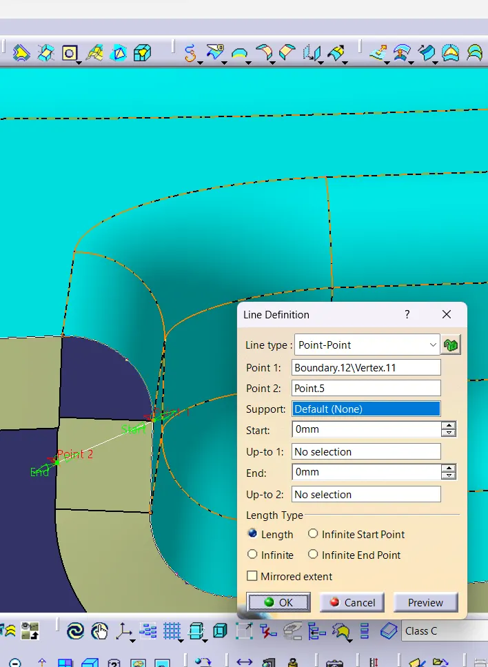
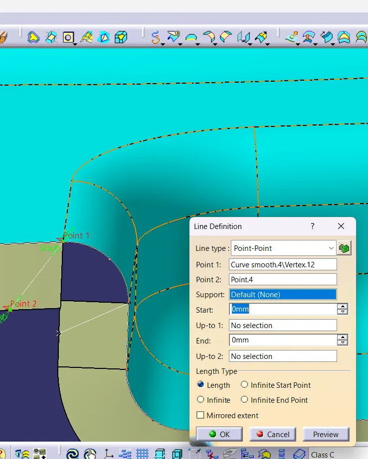
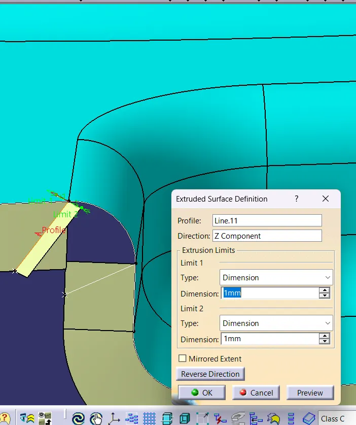
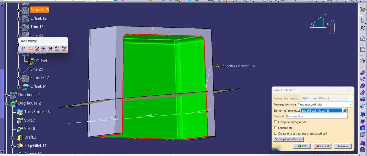
- Extract the surface and mark the points were Dog house need to be made.3
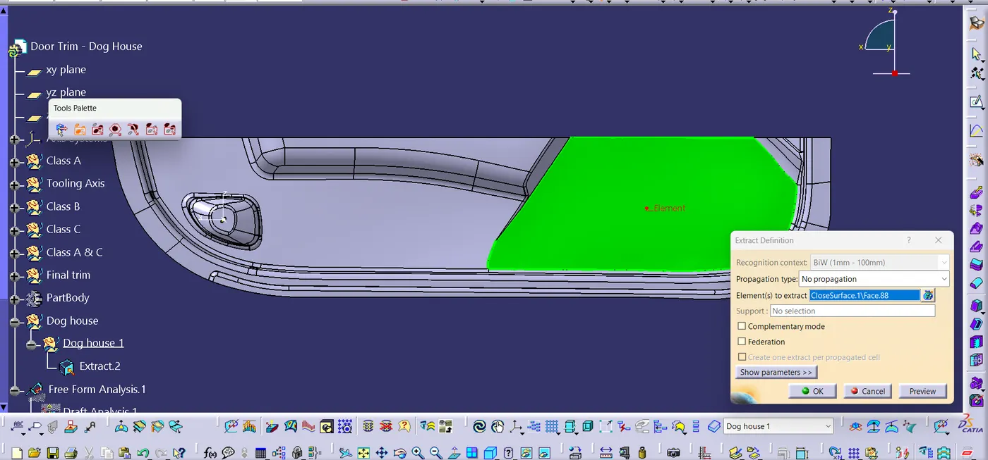
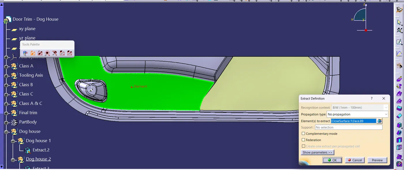
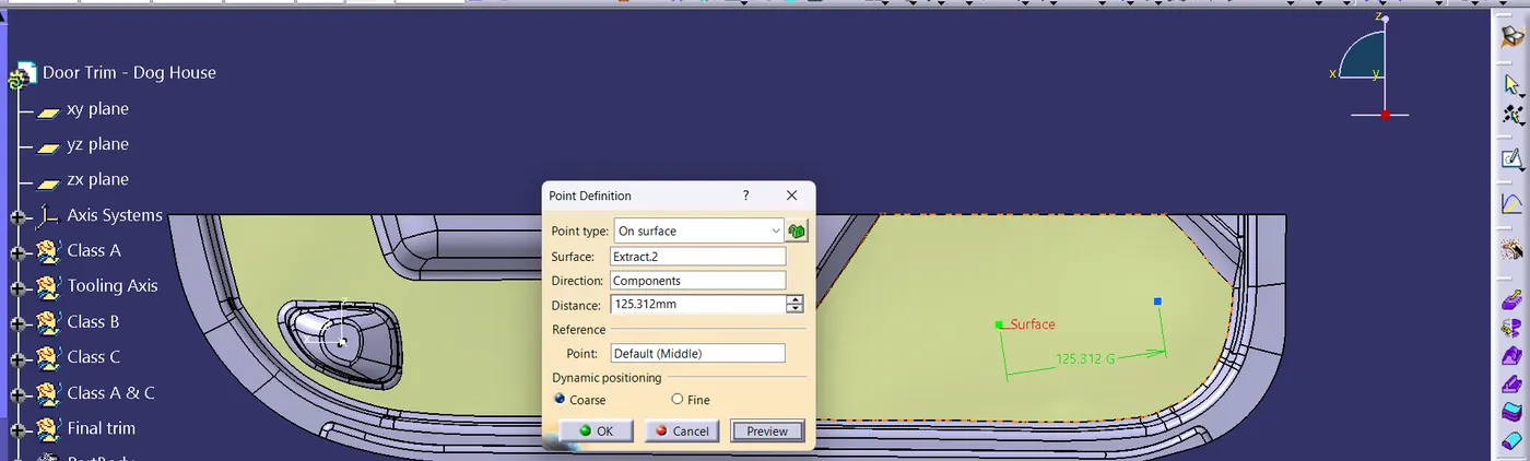
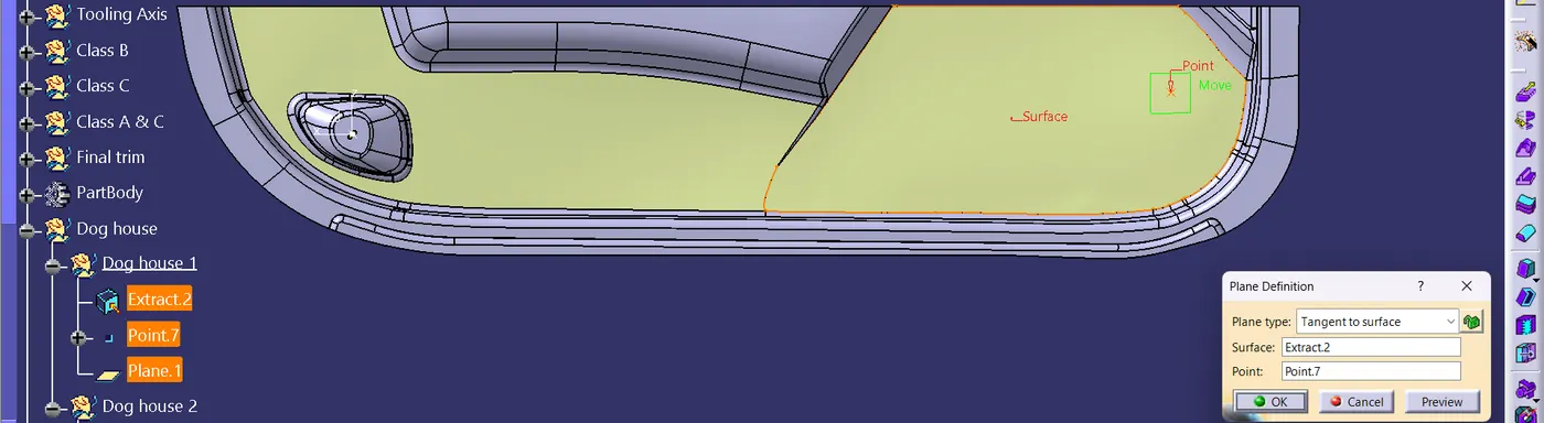
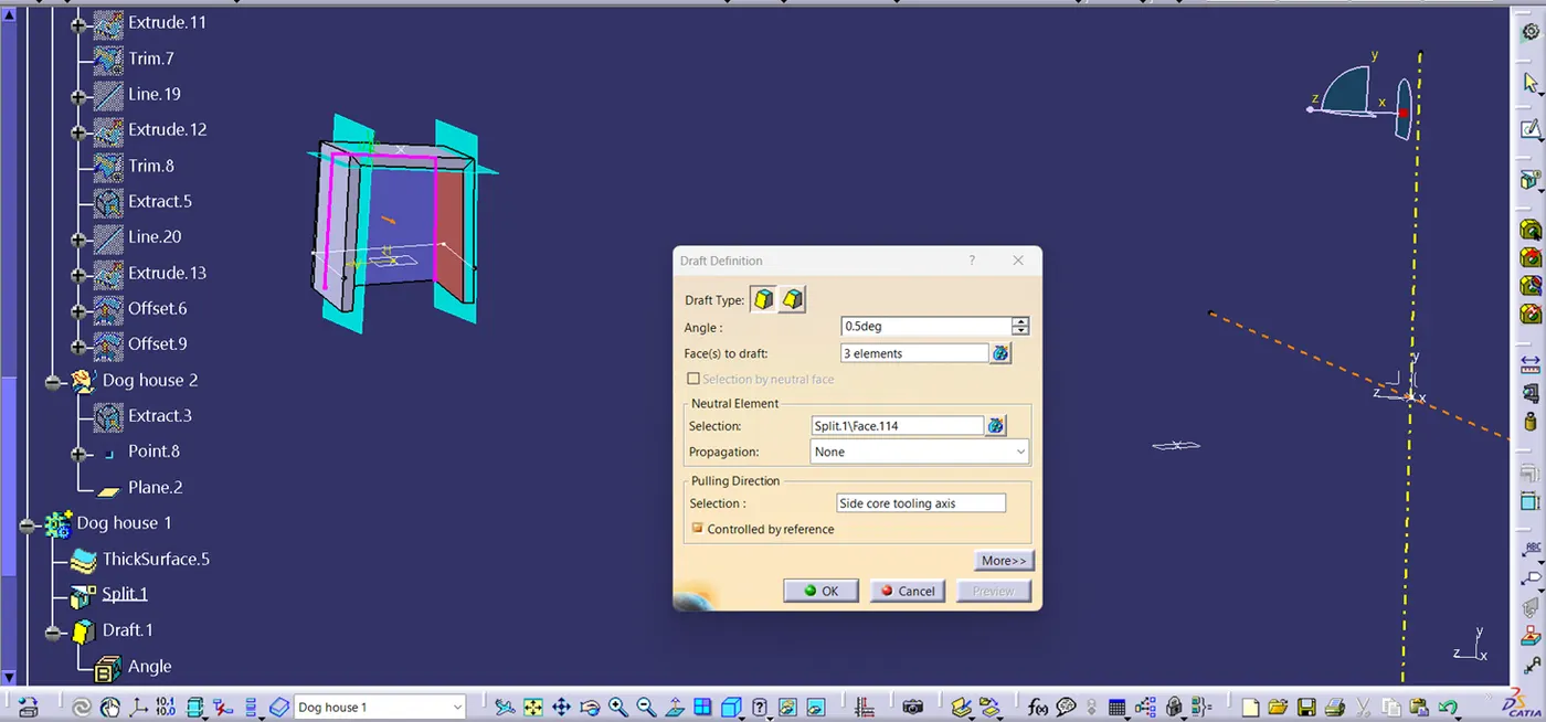
Dog house 1
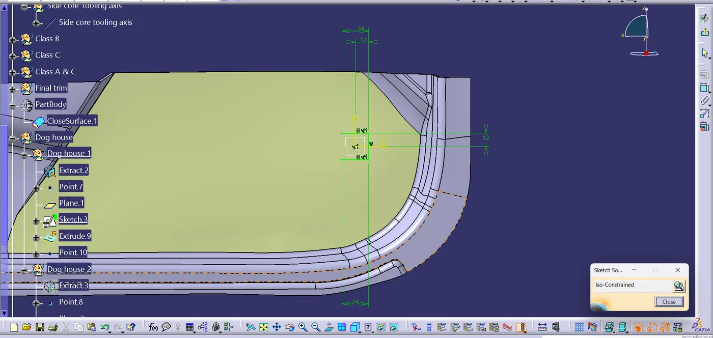
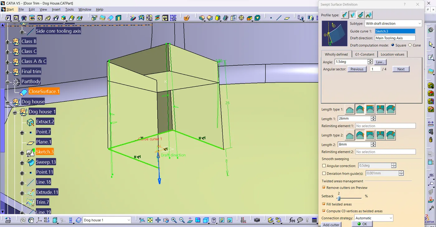
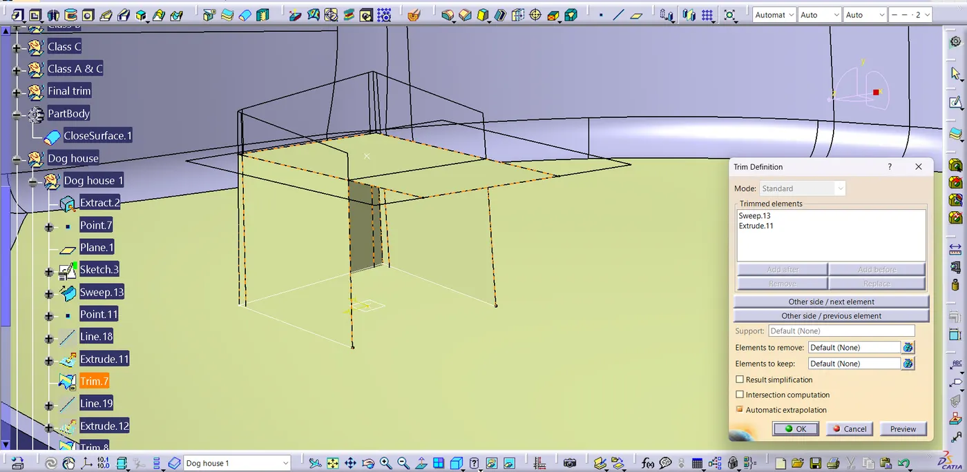
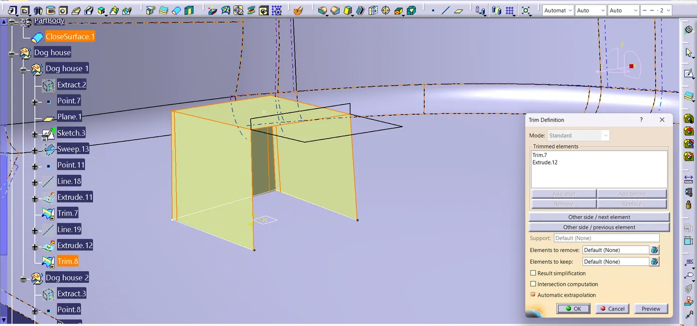
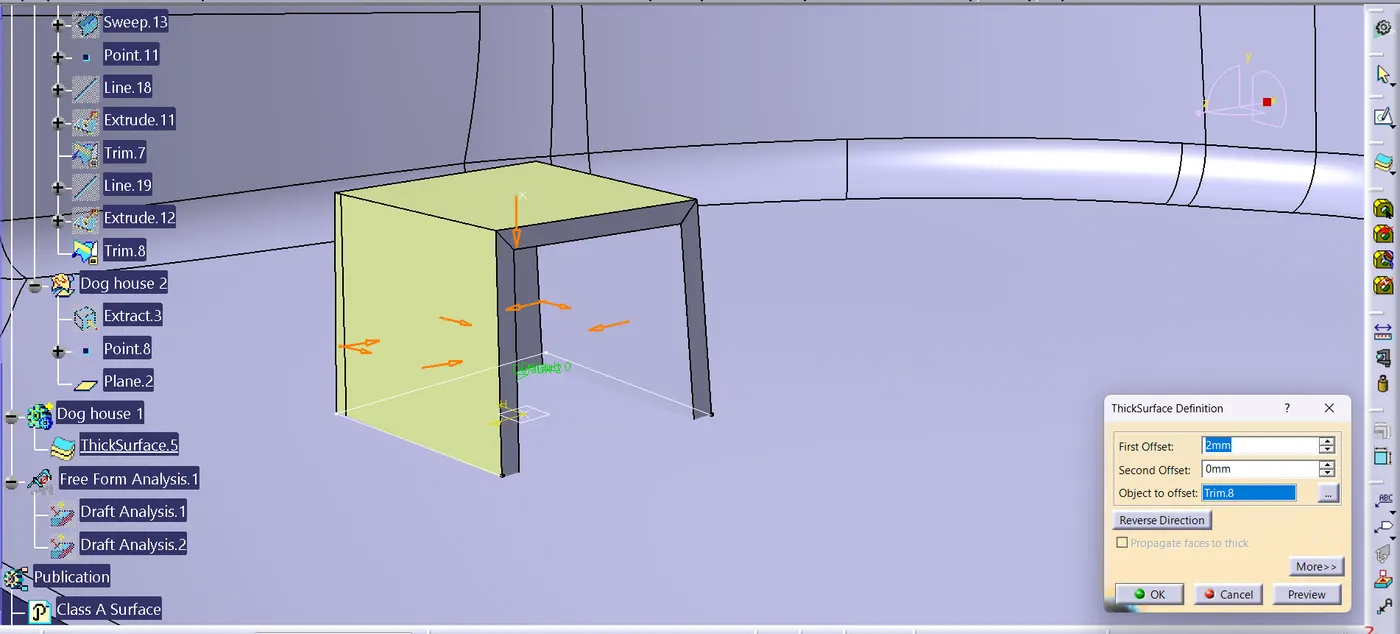
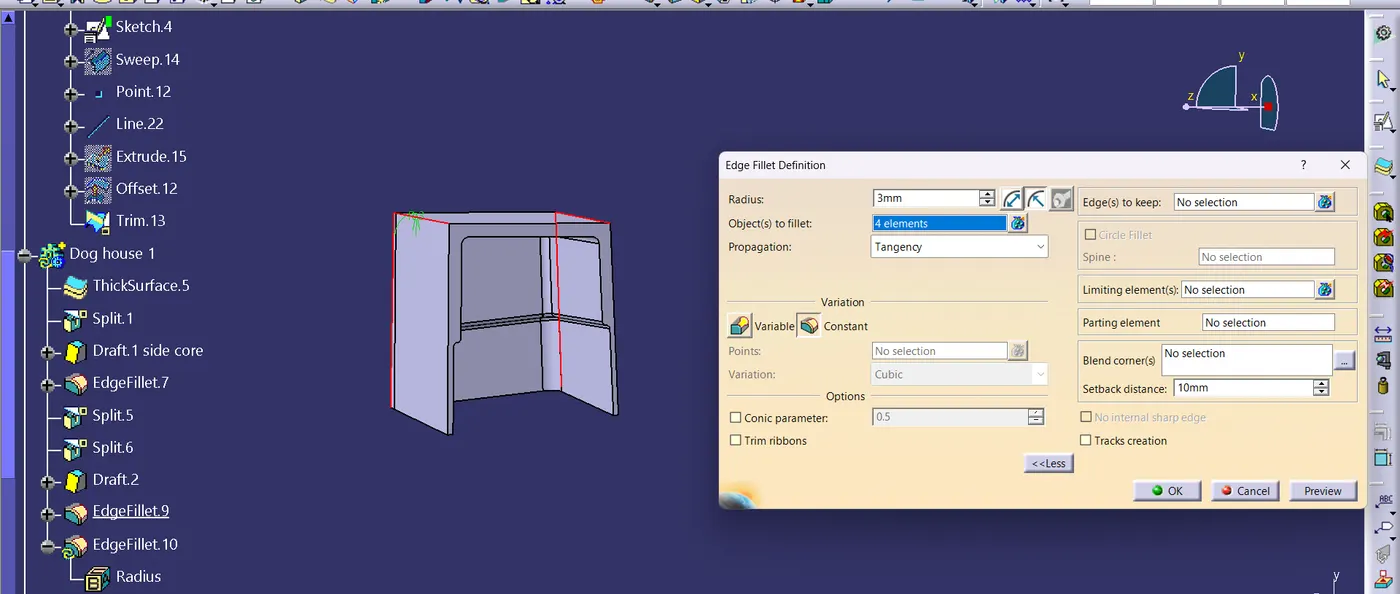
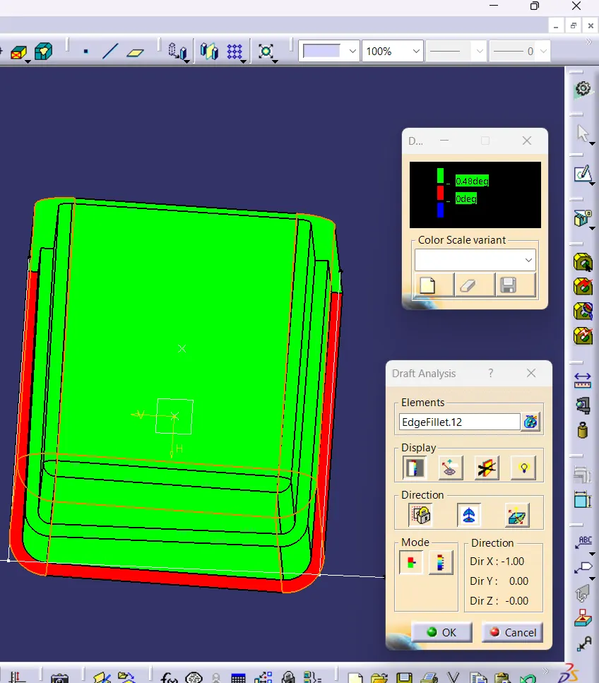
Providing draft of 0.5 degree with side core
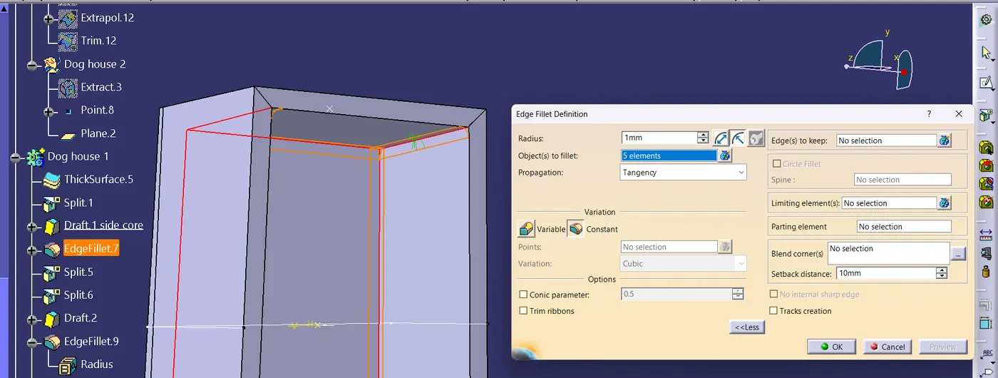
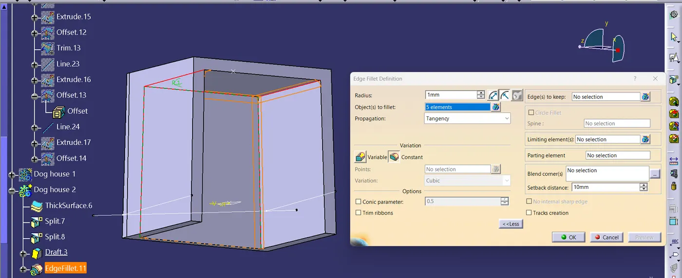
- Lets give a fillet of 1 mm at inside
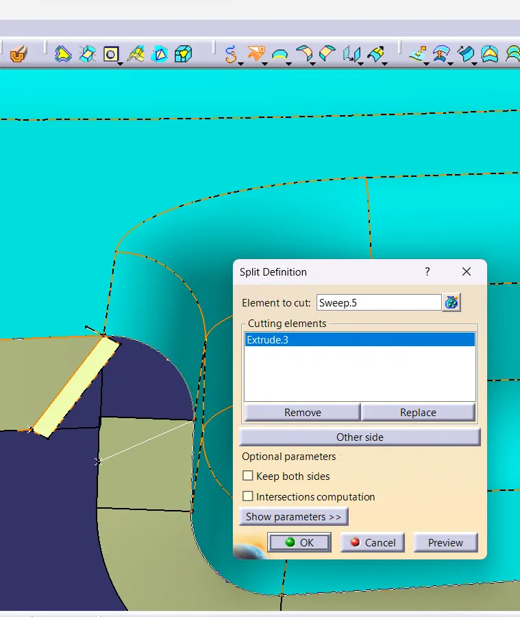
- It is found that front side is having some imperfections, we have to trim and clear the face.
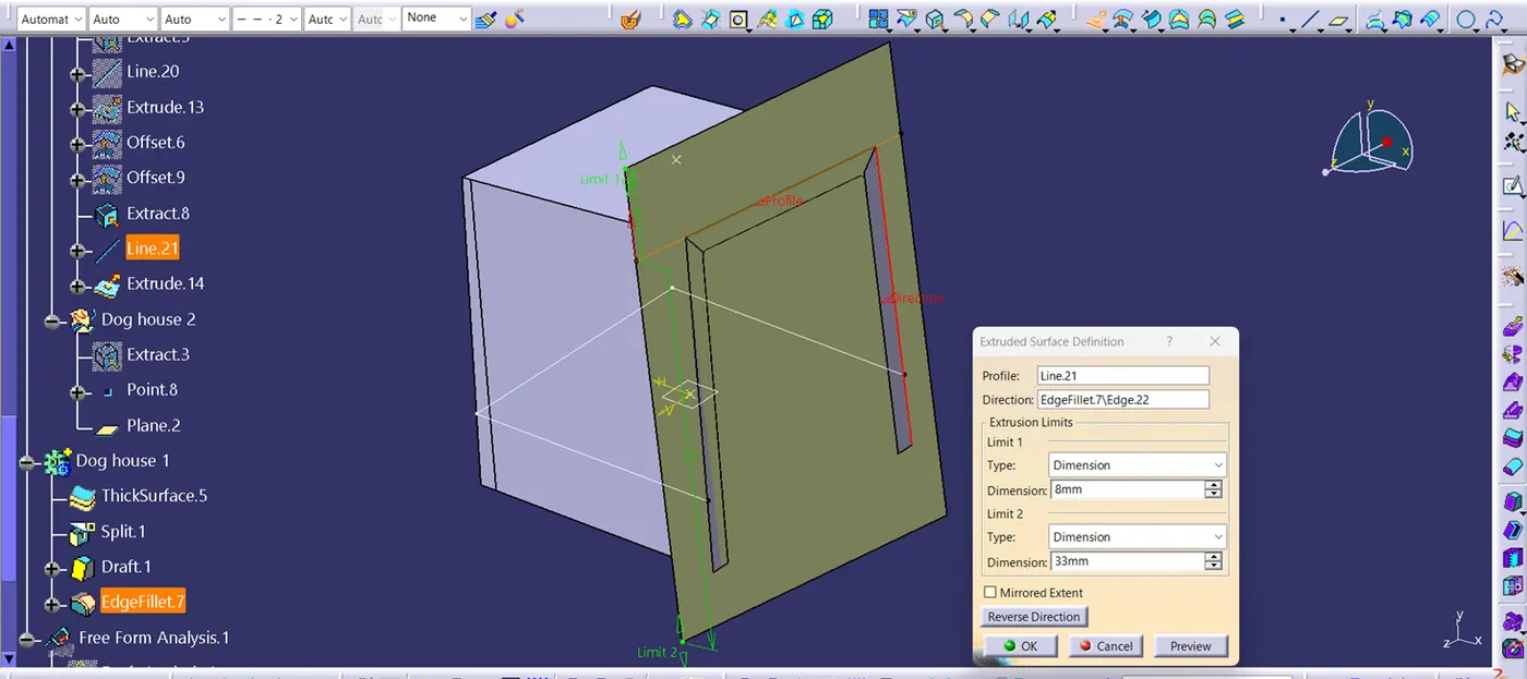
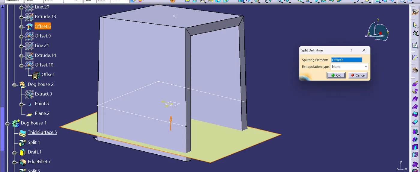
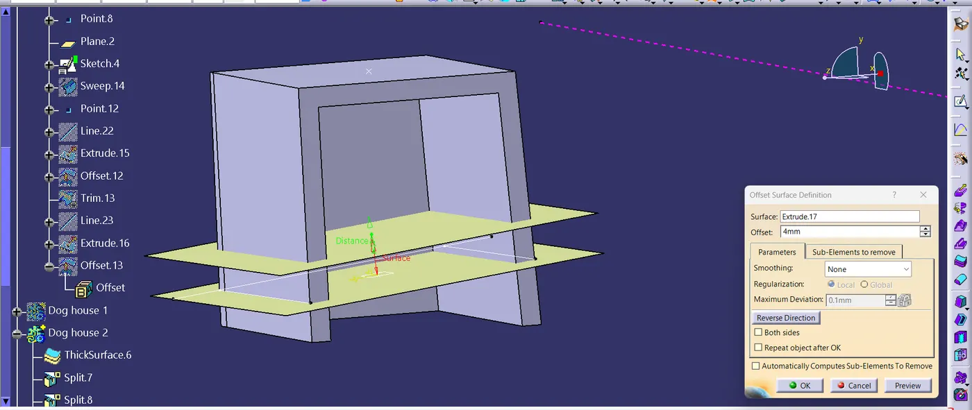
- The height of 'B' should be between 3 -6 mm, here we took 4 mm as height.
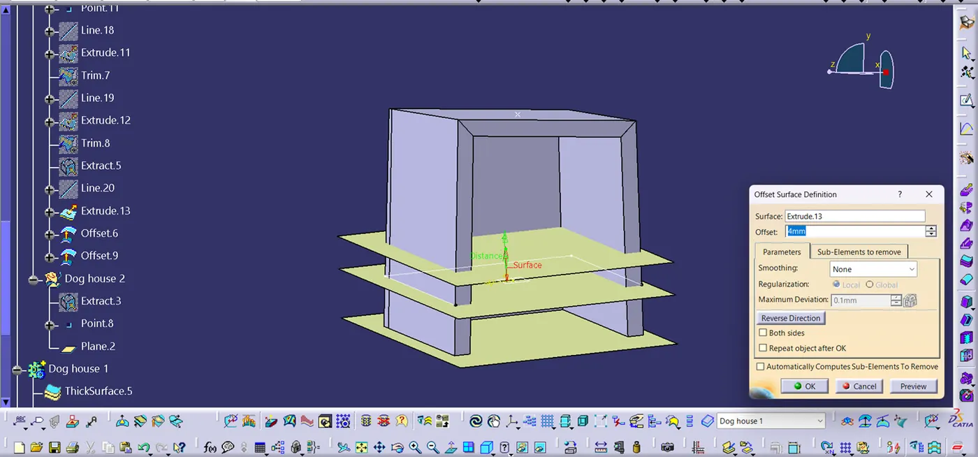
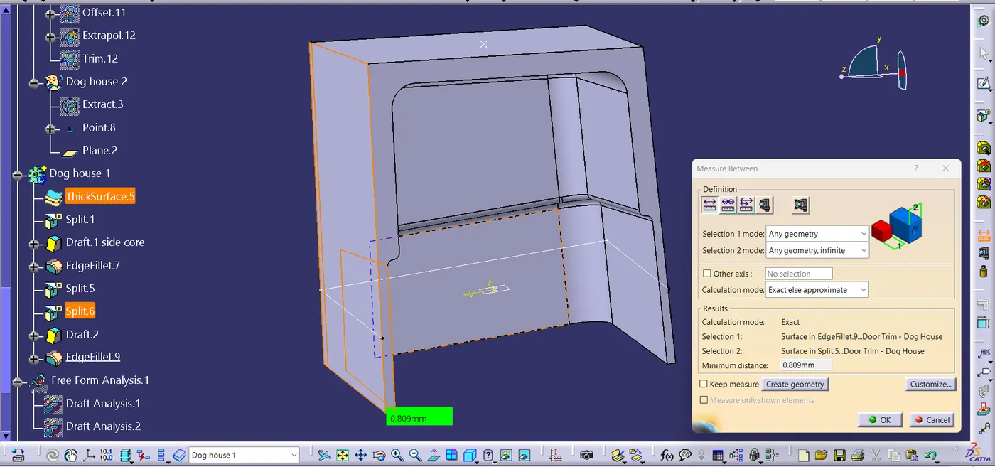
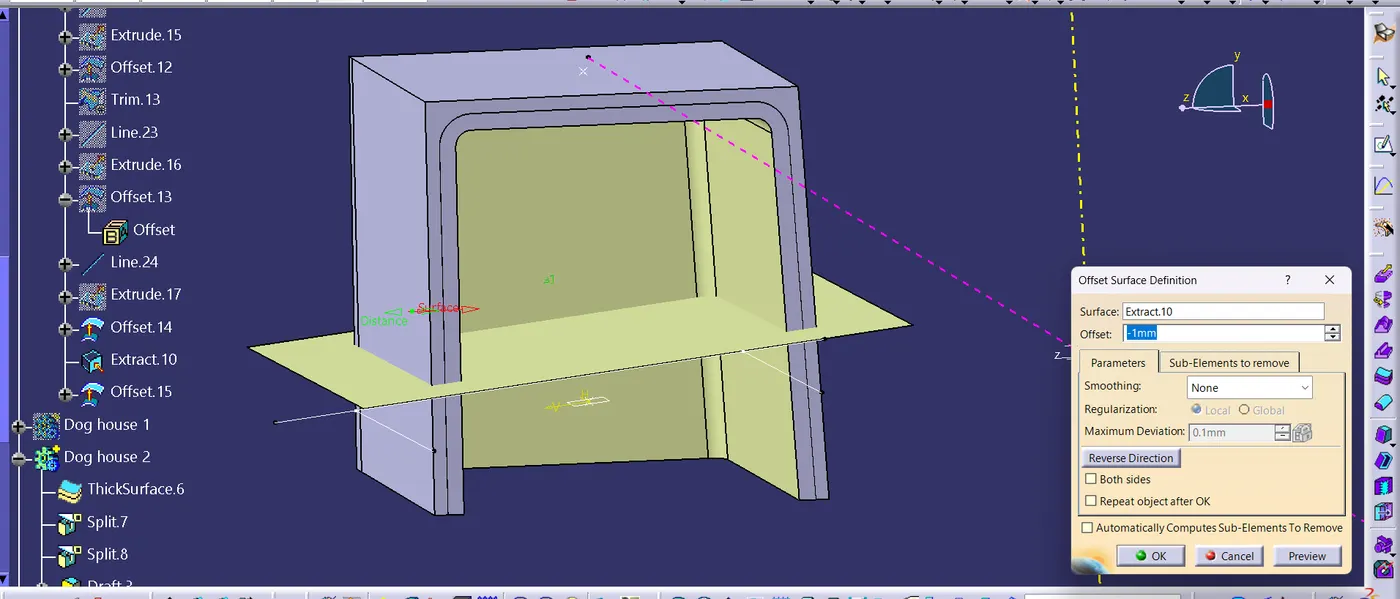
Thickness at C should be 40% of wall thickness = 0.4 * 2.5 mm
= 1 mm
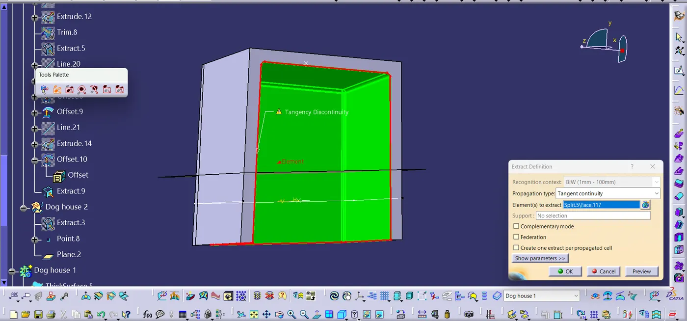
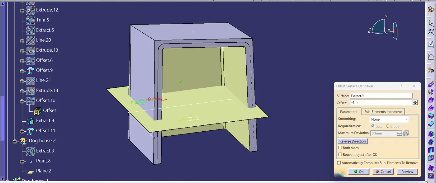
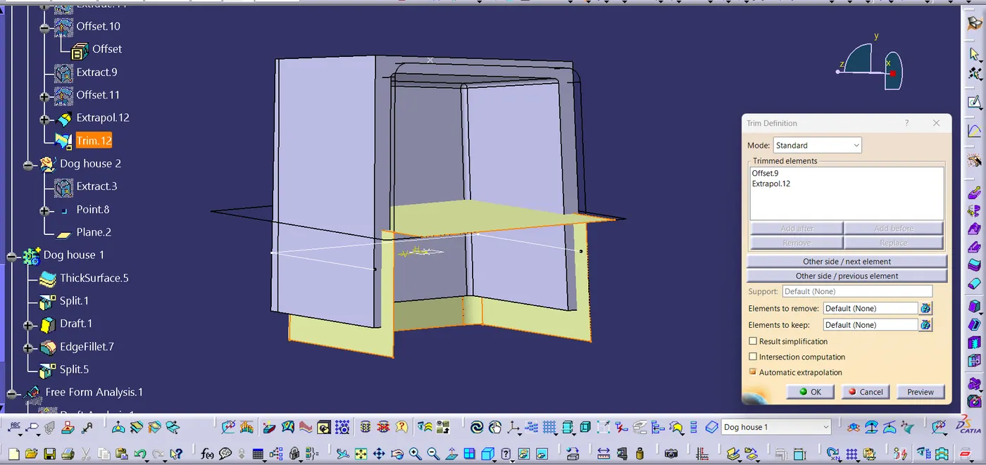
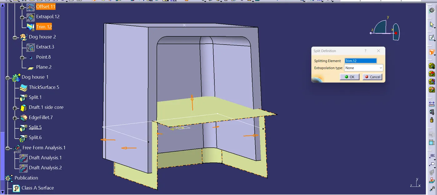
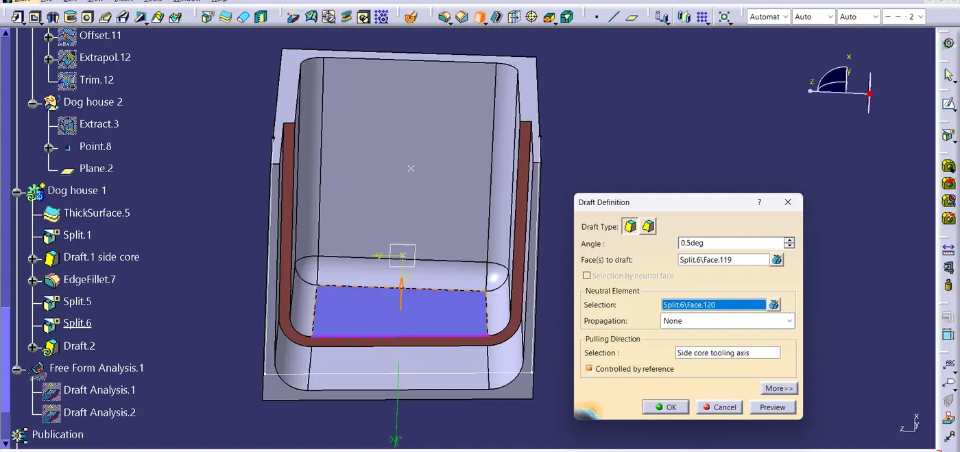
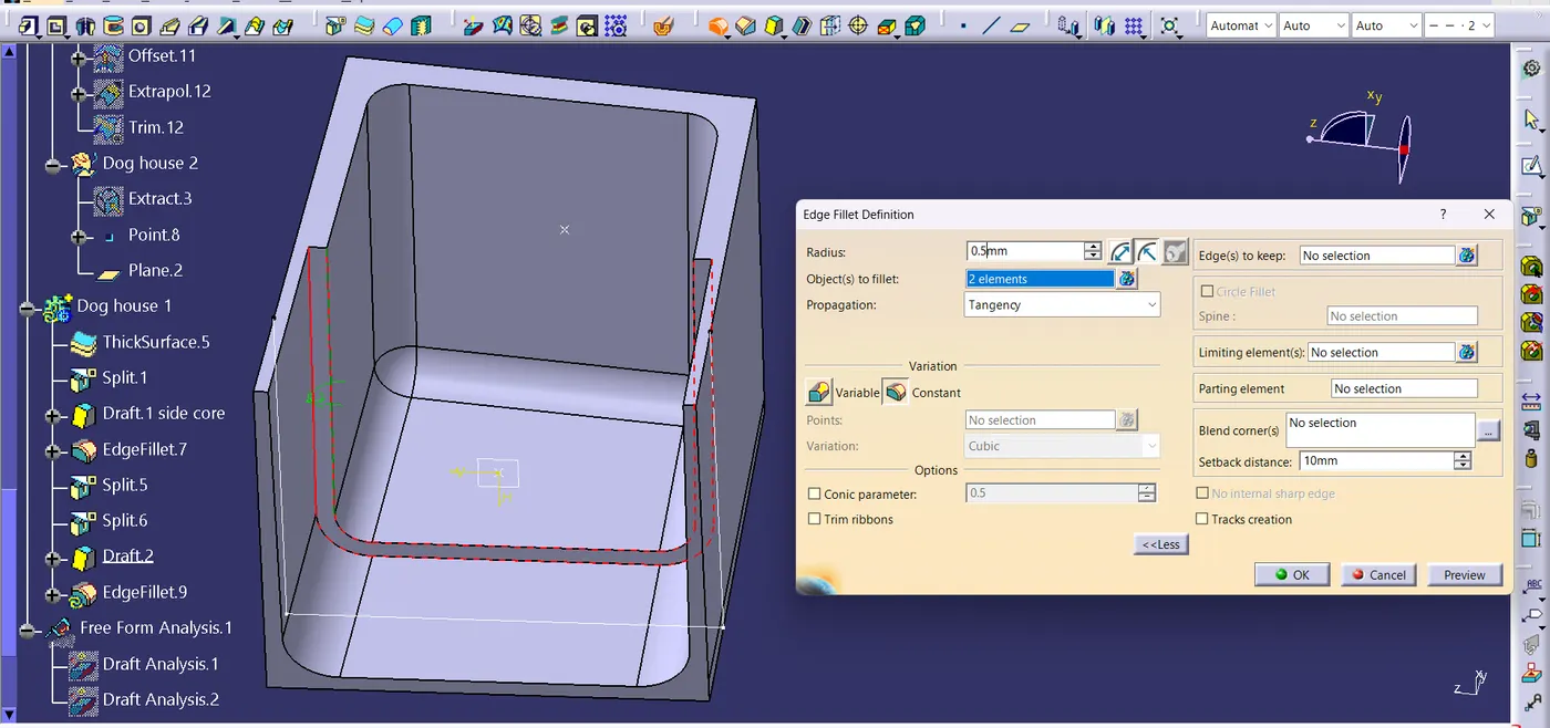
- The wall thickness at intersection is less than 1 mm
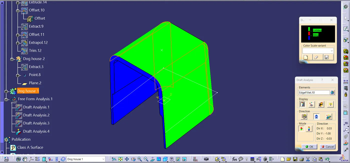
Draft analysis of Dog house 1
Side core draft
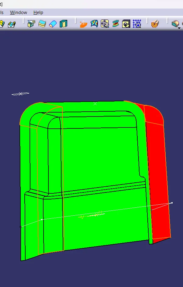
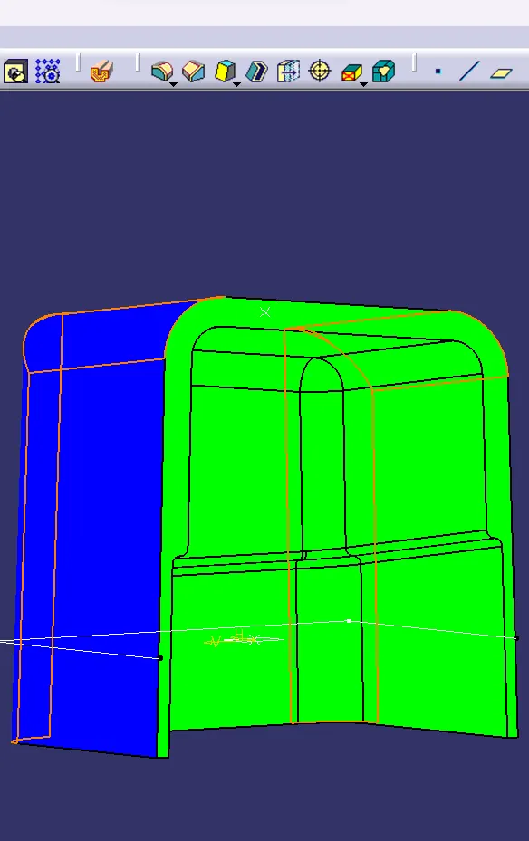
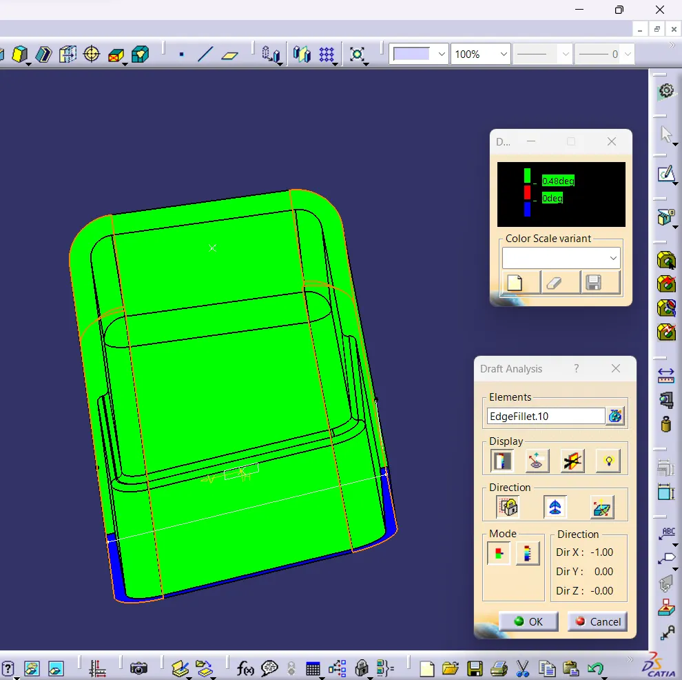
- Here we can find that the draft of 1.5 degree is clearing with the main tooling axis
- Also the draft of 0.5 degree is clearing with the side core axis
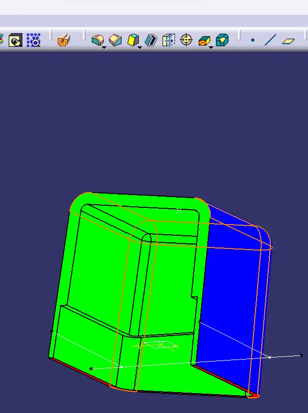
Step 7 : Creating Dog house 2
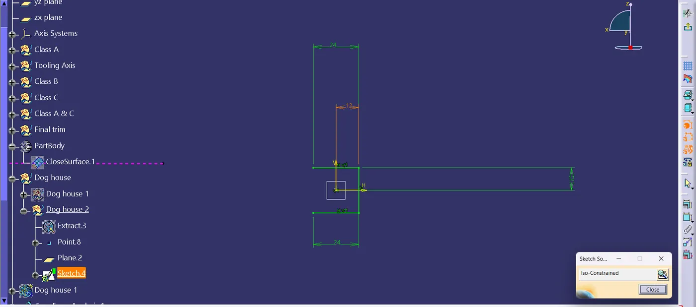
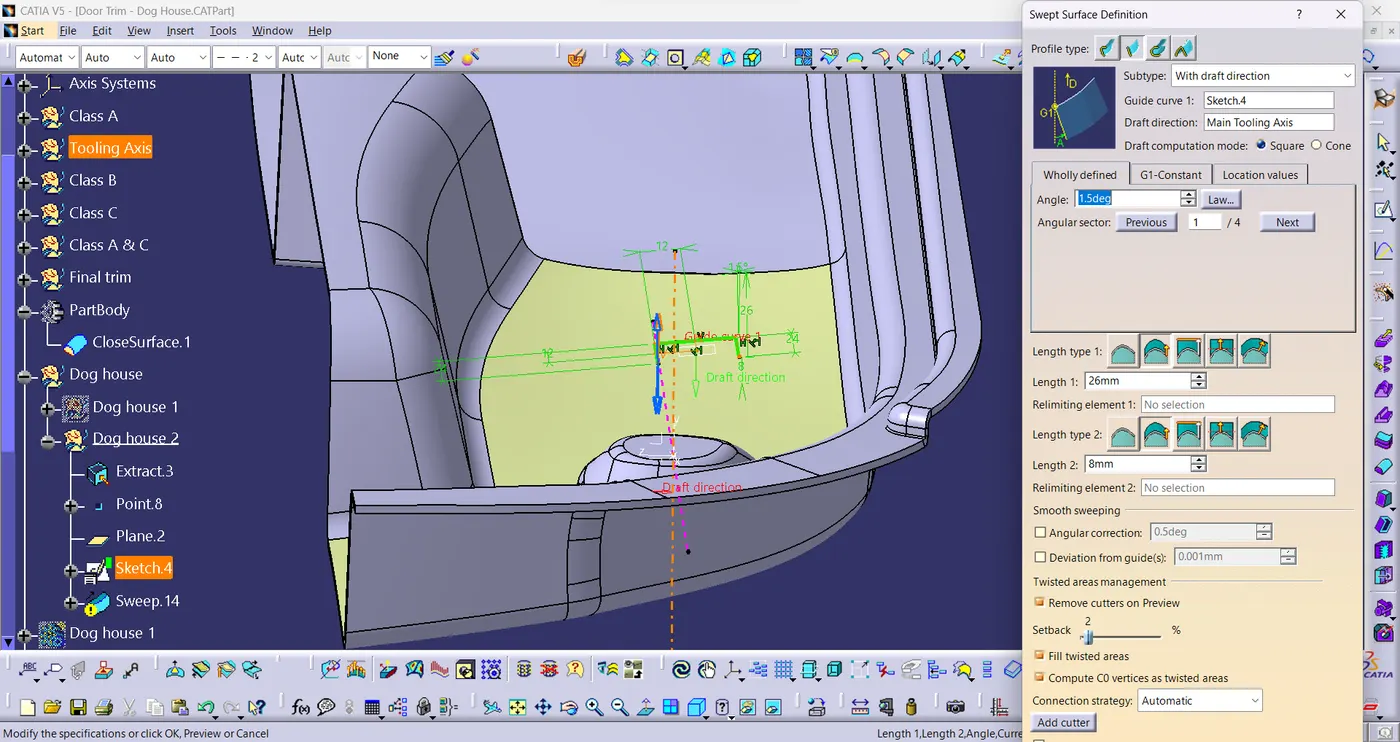
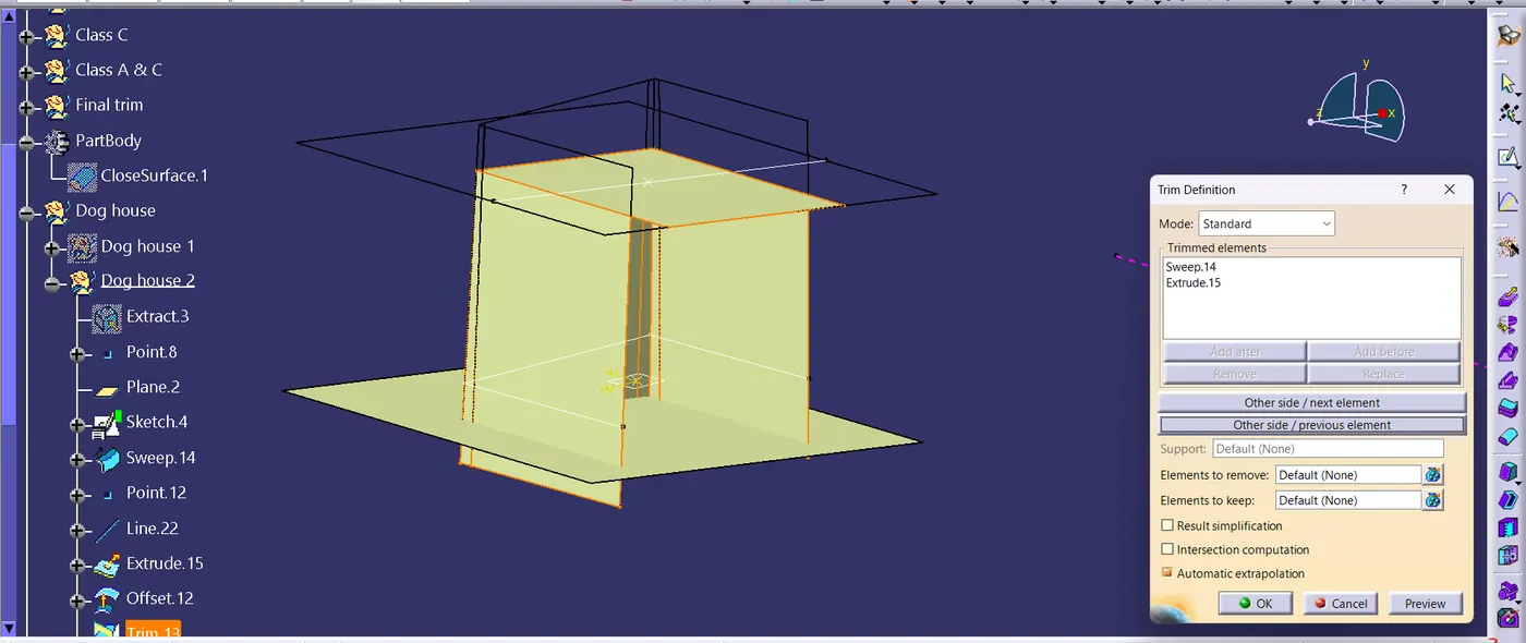
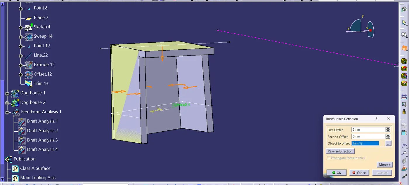
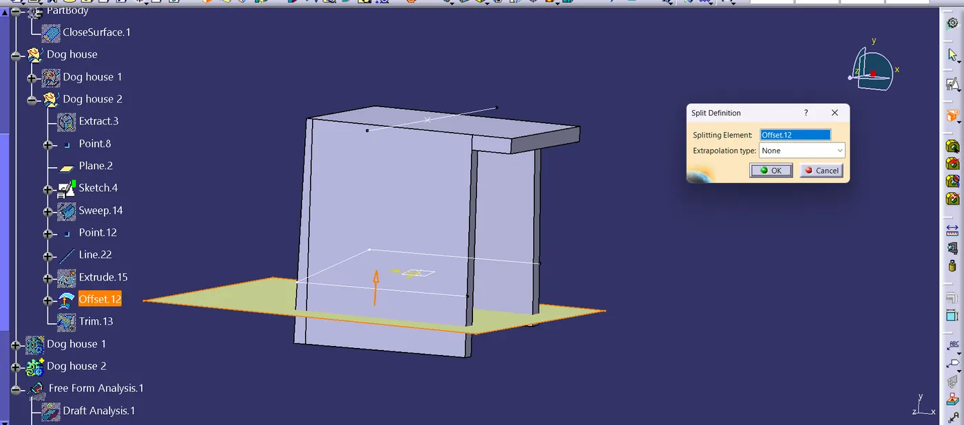
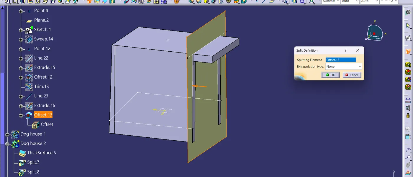
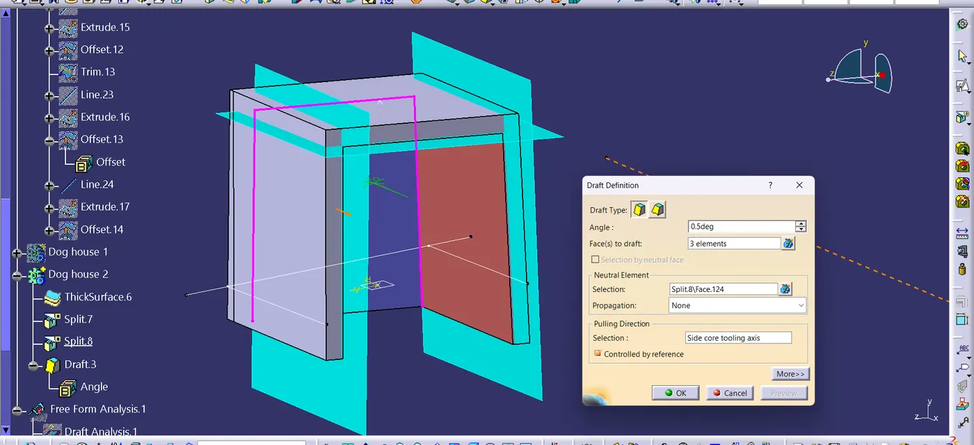
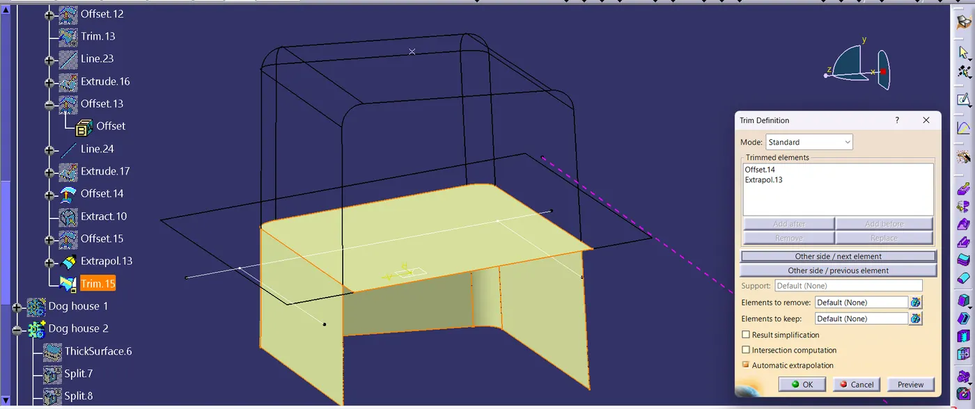
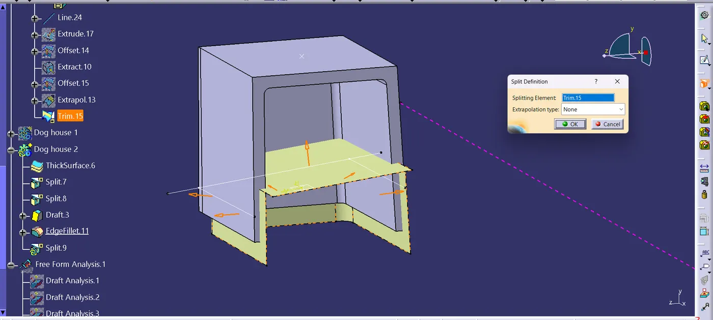
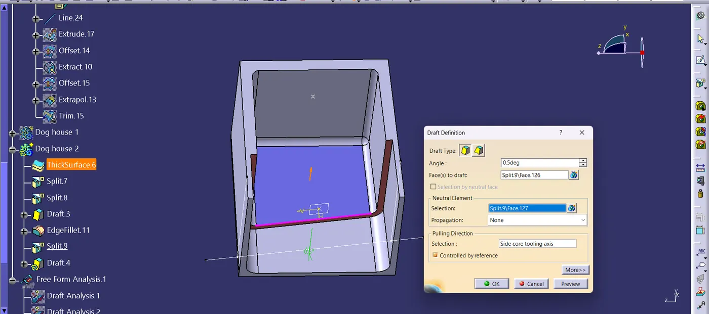
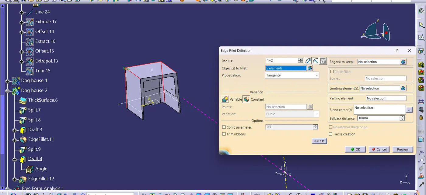
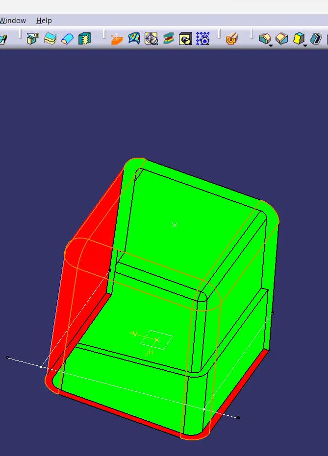
Draft analysis
Draft with side core 0.5 degree
Step 8 : Combine the dog house into main part
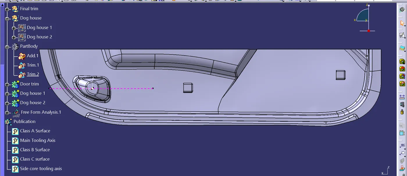
The each dog houses are added to main part using union trim command.
Final draft analysis
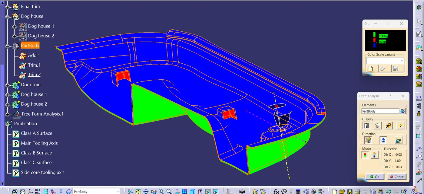
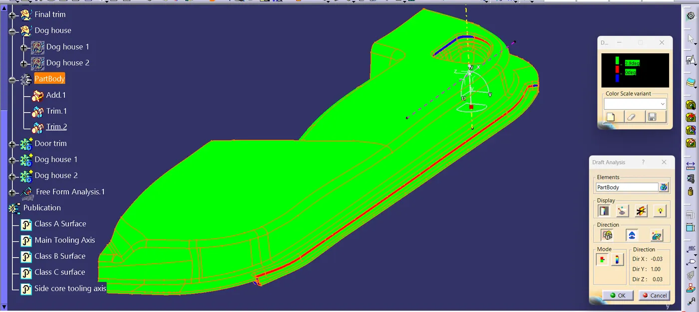
- Most of all the surfaces in class A is clearing the draft
- Other few surfaces need to be modified by the class A designers.
Front view
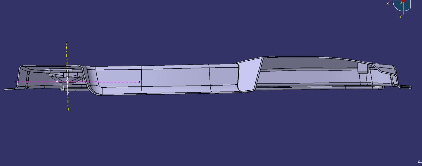
Top view
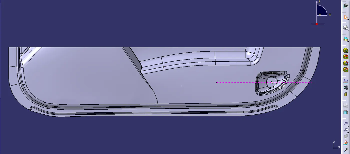
Bottom view
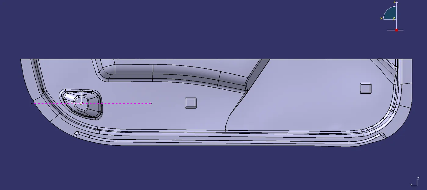
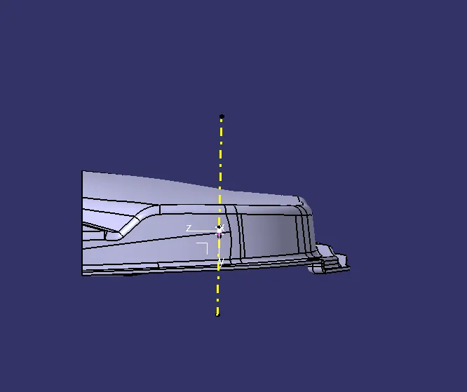
Left side view
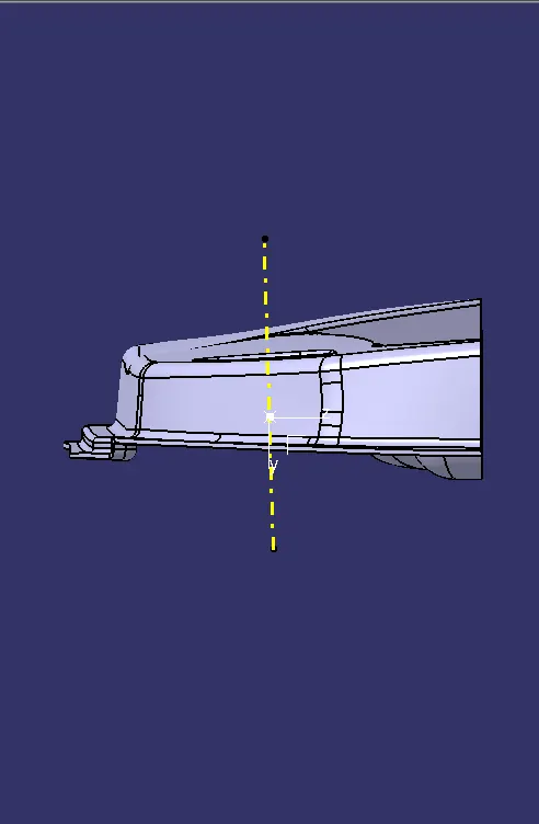
Right side view
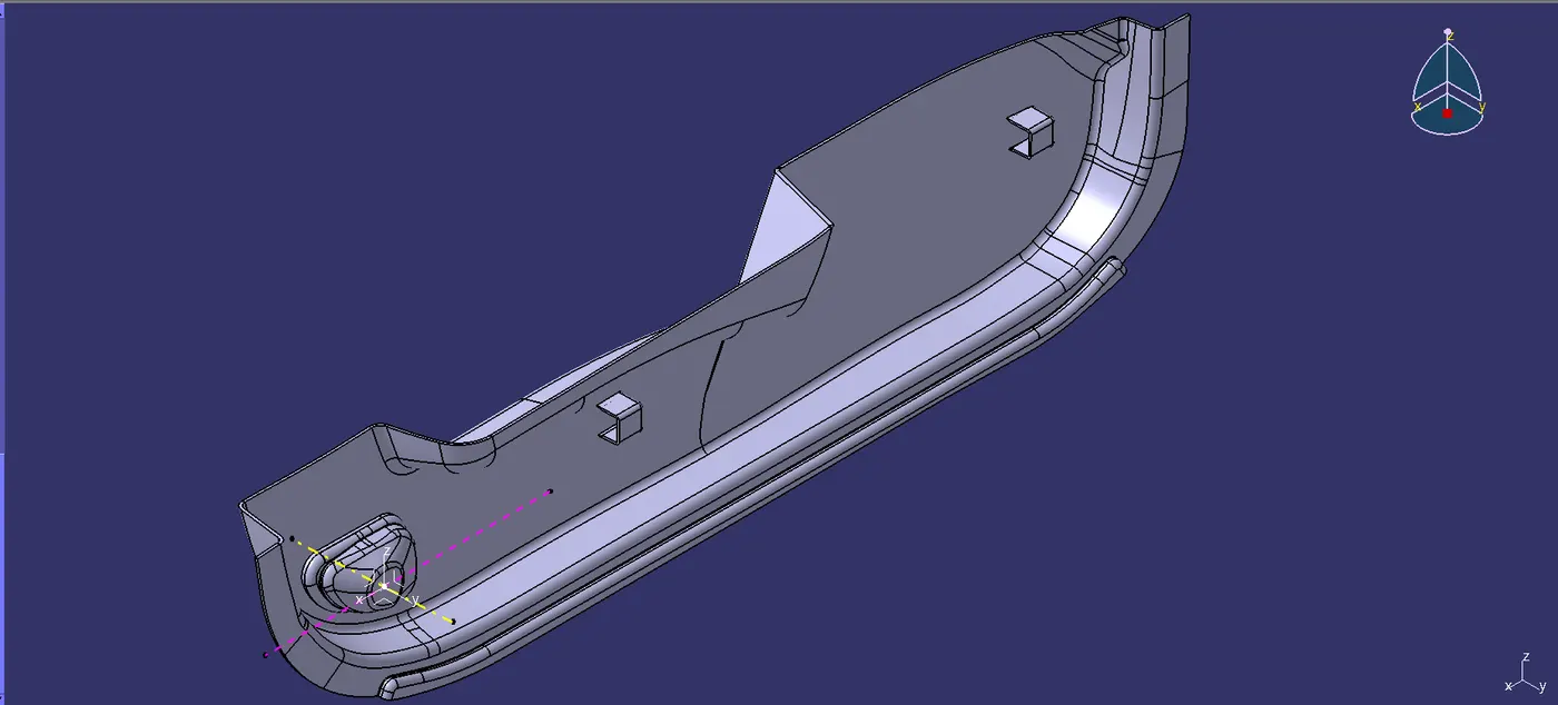
Isometric View
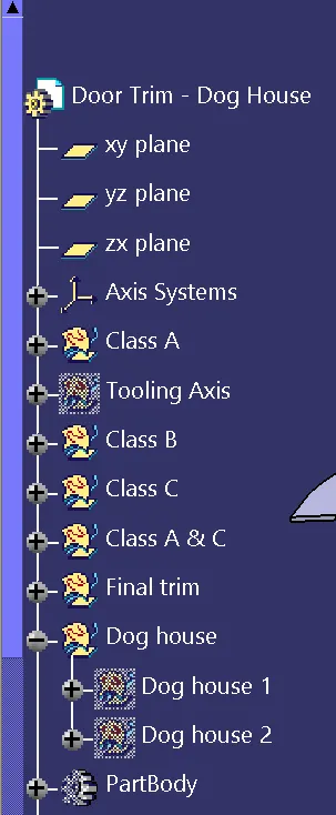
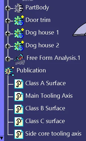
Tree Structure
CONCLUSION
- Created solid part body of Door Trim form class A surface.
- Created the Dog House for the Door Trim.
- Carried out draft analysis