Project 2 Thermal modeling of battery pack
AIM
To model a 10 cell series lithium ion battery model and simulate the thermal effects and compare life cycle performance at various temperatures, charge & discharge rates using MATLAB.
THEORY
Lithium Ion Cells
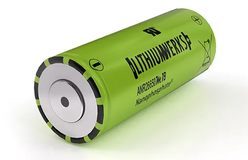
A lithium-ion cell is a type of rechargeable battery that uses lithium ions as the primary carrier of electric charge. It is a highly popular battery technology due to its high energy density, low self-discharge rate, and low maintenance requirements. Lithium-ion cells are commonly used in a wide range of consumer electronics devices, such as smartphones, laptops, and cameras, as well as electric vehicles.
The lithium-ion cell consists of three main components: the cathode, the anode, and the electrolyte. The cathode is typically made of lithium cobalt oxide, lithium manganese oxide, or lithium iron phosphate, while the anode is made of graphite or other carbon-based materials. The electrolyte is usually a lithium salt in an organic solvent.
During charging, lithium ions move from the cathode to the anode through the electrolyte, where they are stored in the anode's porous structure. During discharge, the ions move back to the cathode, generating an electrical current that can power a device.
One of the main advantages of lithium-ion cells is their high energy density, which means they can store more energy per unit of weight or volume compared to other battery technologies. They also have a low self-discharge rate, which means they can hold their charge for longer periods of time. Additionally, lithium-ion cells have a long cycle life, meaning they can be charged and discharged multiple times without significant loss of performance.
However, there are some limitations to lithium-ion cells, such as their sensitivity to high temperatures and their potential for thermal runaway, which can lead to fires or explosions. As with all battery technologies, proper handling, storage, and disposal are important to ensure safe and optimal performance.
Battery pack
A battery pack is a collection of batteries that are arranged in a single unit or enclosure. The batteries in a pack can be connected in various configurations, such as series, parallel, or series-parallel, to achieve the desired voltage and capacity.
Battery packs are commonly used in a variety of applications, such as portable electronic devices, power tools, electric vehicles, and backup power systems. They are used to store and deliver electrical energy, which can be used to power devices or provide backup power during power outages or in remote locations where grid power is not available.
Battery packs can be made up of different types of batteries, such as lithium-ion, nickel-cadmium, or lead-acid, depending on the application and desired performance characteristics. The batteries are typically housed in a protective enclosure that is designed to prevent damage from overcharging, over-discharging, and over-temperature conditions.
The advantages of battery packs are their portability, scalability, and flexibility. They can be easily transported and installed in various locations, and their capacity and voltage can be adjusted by adding or removing batteries or changing the connection configuration. However, battery packs can be sensitive to environmental factors, such as temperature and humidity, which can affect their performance and lifespan.
Types of battery pack configuration
1. Single-cell configuration
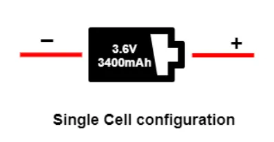
The single-cell configuration is the simplest battery pack. This configuration is available in a wall clock, memory backup, and wristwatch. These all are low-power devices, so they use a 1.5 V alkaline battery. Mobile phones and tablets are also available in a single-cell configuration of a 3.6 V Li-ion battery. The image below shows the single-cell configuration of the li-ion battery.
2. Series configuration
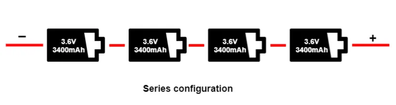
Connecting batteries in series means connecting the positive terminal of one battery to the negative terminal of another battery. This configuration increases the voltage of the batteries while the capacity remains the same. For example, if you connect two 12-volt batteries in series, you will get a total voltage of 24 volts, but the capacity will remain the same as a single battery. The advantage of a series connection is that it allows for higher voltage, which is useful in applications where high voltage is required, such as electric vehicles or solar power systems.
3. Parallel configuration
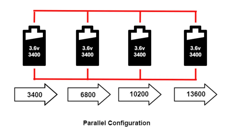
Connecting batteries in parallel means connecting the positive terminal of one battery to the positive terminal of another battery and the negative terminal of one battery to the negative terminal of another battery. This configuration increases the capacity of the batteries while the voltage remains the same. For example, if you connect two 12-volt batteries in parallel, you will get a total capacity of two times the capacity of a single battery, but the voltage will remain the same as a single battery. The advantage of a parallel connection is that it allows for higher capacity, which is useful in applications where longer runtimes are required.
4. Series – parallel configuration
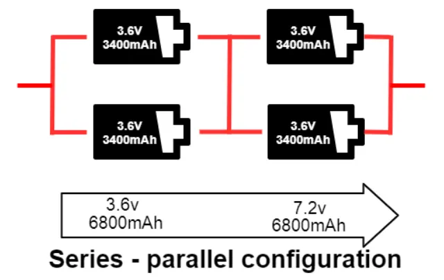
Connecting batteries in both series and parallel is a combination of the above two configurations. This configuration allows for both voltage and capacity to be increased. For example, if you connect two sets of two 12-volt batteries in series and then connect those sets in parallel, you will get a total voltage of 24 volts and a total capacity of two times the capacity of a single set of batteries. This configuration is commonly used in applications such as electric vehicles, where high voltage and high capacity are required.
SIMULINK MODEL
A Default Matlab Simulink Model of Lithium-lon Battery Pack With Fault is used for 10-cell Battery Pack Thermal Modelling
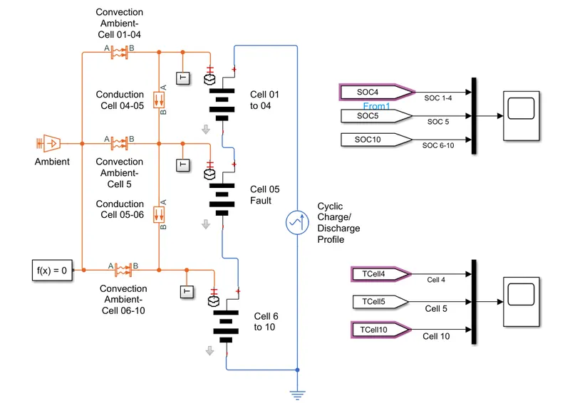
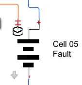
This above model shows how to simulate a battery pack consisting of multiple series-connected cells in an efficient manner. It also shows how a fault can be introduced into one of the cells to see the impact on battery performance and cell temperatures. For efficiency, identical series-connected cells are not just simply modeled by connecting cell models in series. Instead a single cell is used, and the terminal voltage scaled up by the number of cells. The fault is represented by changing the parameters for the Cell 5 Fault subsystem, reducing both capacity and open-circuit voltage, and increasing the resistance values.
Cell 01 to 04 Subsystem:
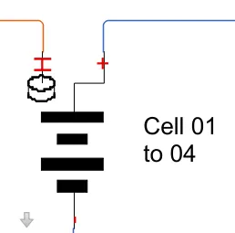
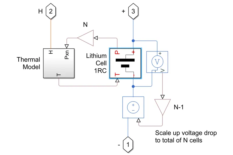
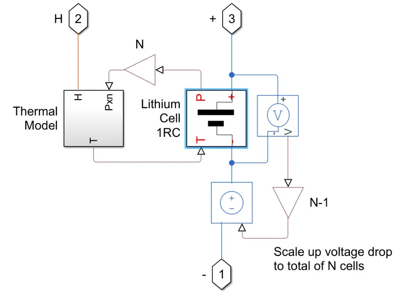
- Cell subsystem consists of a Thermal Model and Lithium Cell 1RC block which calculates the temperature and thermal effect of the battery pack.
- It consists of PS Gain block,Controlled Voltage Source and Voltage Sencor.
- The voltage sensor block represents an ideal voltage sensor, that's converts voltage measured between any electrical connections into a physical signal proportional to the voltage.
- A controlled voltage source represents an ideal voltage source that maintain the specified voltage at its output regardless of the current passing through it.
Thermal Model Subsystem Block -
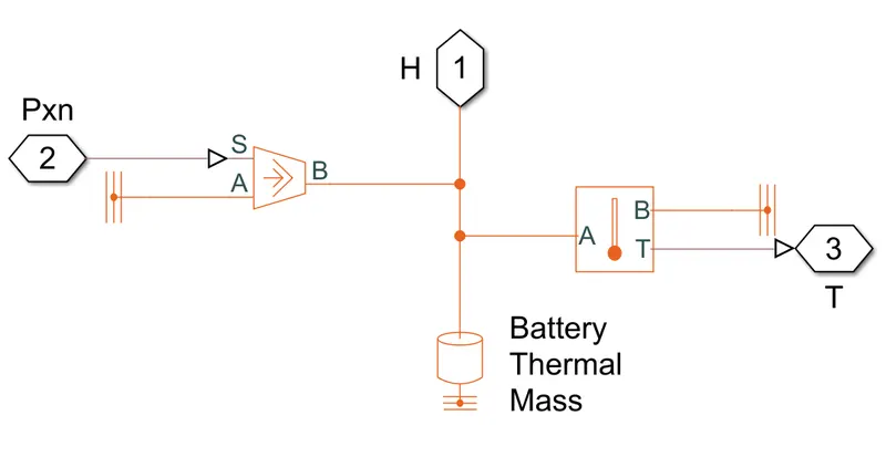
This block consists of the following blocks:
- Thermal Reference- This block represents a reference point in a thermal network where the temperature is equal to absolute zero.
- Controlled heat flow rate source- This block represents an ideal energy source in a thermal network that can maintain a controlled heat flow rate regardless of the temperature difference. The heat flow rate is set by the physical signal port S. A positive heat flow rate
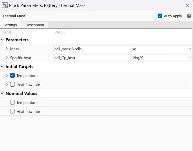
flows from port A to port B. - Thermal Mass - This block model internal energy storage in a thermal network. The rate of temperature increase is proportional to the heat flow rate into the material and inversely proportional to the mass and specific heat of the material.
- Temperature Sensor- This block measures temperature in a thermal network. There is no heat flow through the sensor. The physical signal port T reports the temperature difference across the sensor. The measurement is positive when the temperature at port A is greater than the temperature at port B.
Lithium Cell 1RC Subsystem Block-
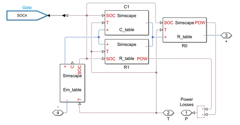
- This block consists of capacitance value table which depends on an external physical signal inputs SOC and T. It is assumed that the capacitance value is slowly varying with time, and hence the equationi = C'dv/dt holds.
- Resistance value (R) table which depends on an external physical signal inputs SOC and T.
- Voltage value (EM) which implements the cell's main branch voltage source, and determines values for capacity (C) and state of charge (SOC). The defining equations depend on cell temperature, T.
- A goto block is used to take the SOC of cells 1-4 and send to the scope block outside the subsystem
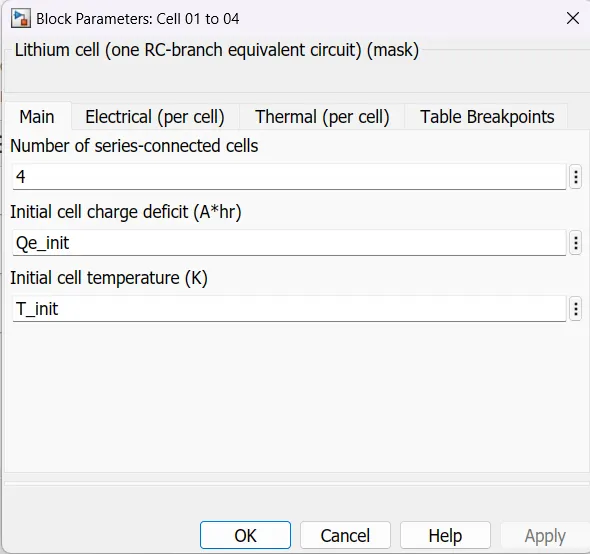
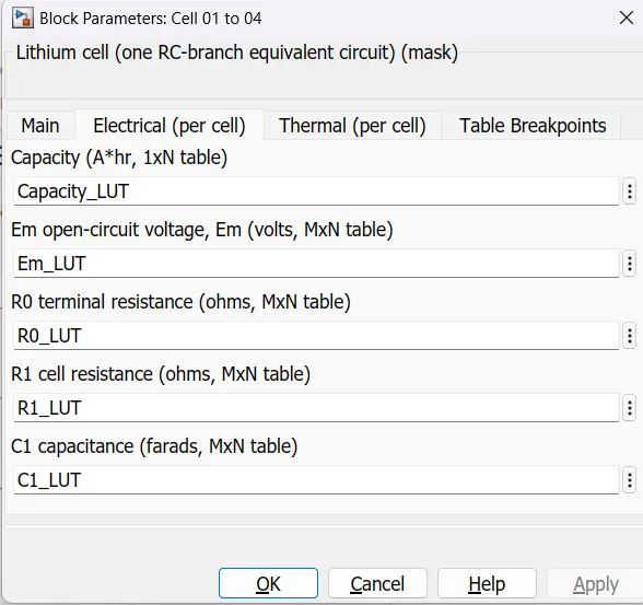
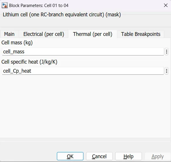
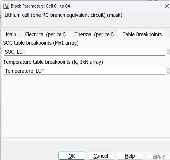
Block Parameters For Cells 01 to 04 :
Cell 05 Subsystem:
Thermal Model & Lithium Cell 1RC Subsystem Block-
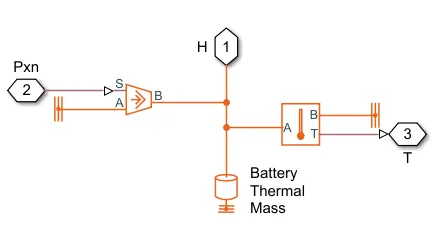
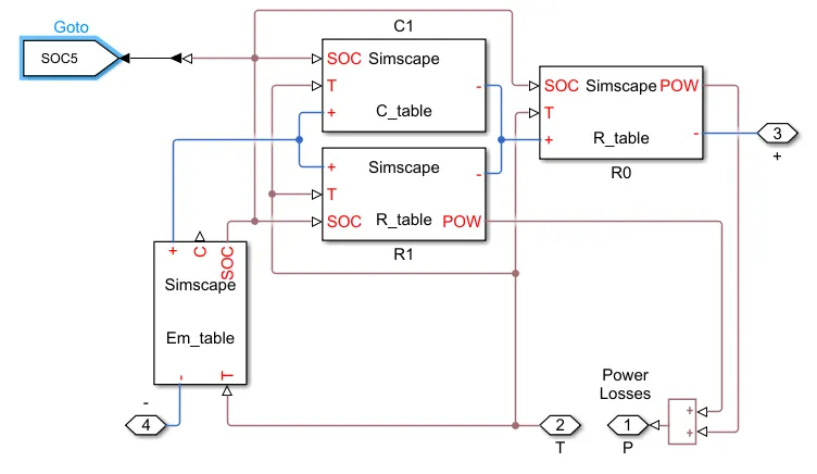
Block Parameters For Cells 05 :
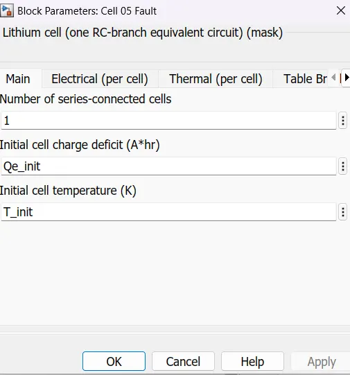
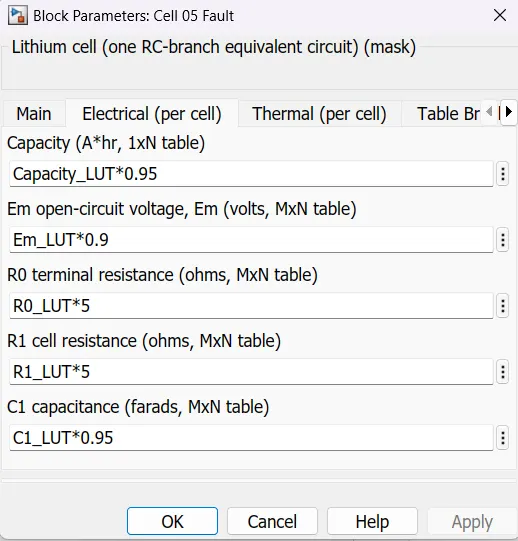
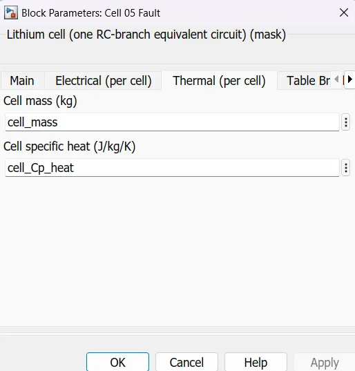
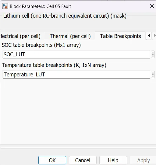
Inorder to make the cell faulty, some changes in the Electrical system of the cell is done.
Cell 06 to 10 Subsystem:
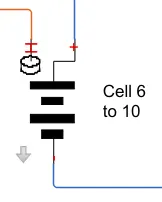
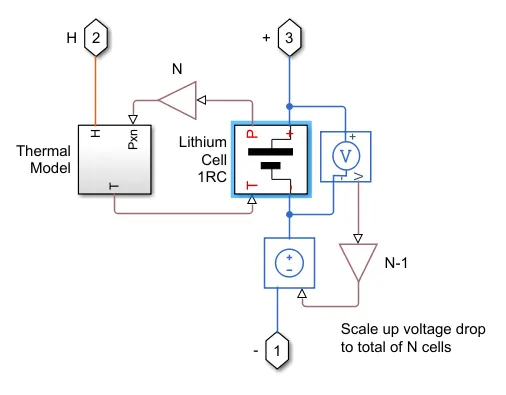
Thermal Model & Lithium Cell 1RC Subsystem Block-
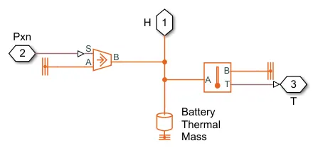
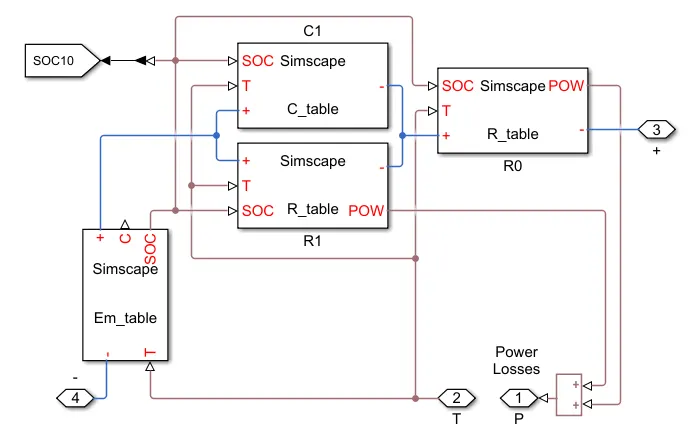
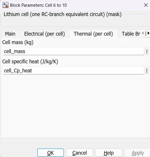
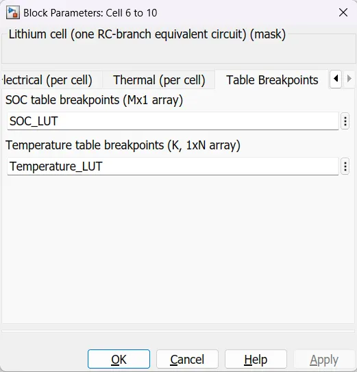
Block Parameters For Cells 06 to 10 :
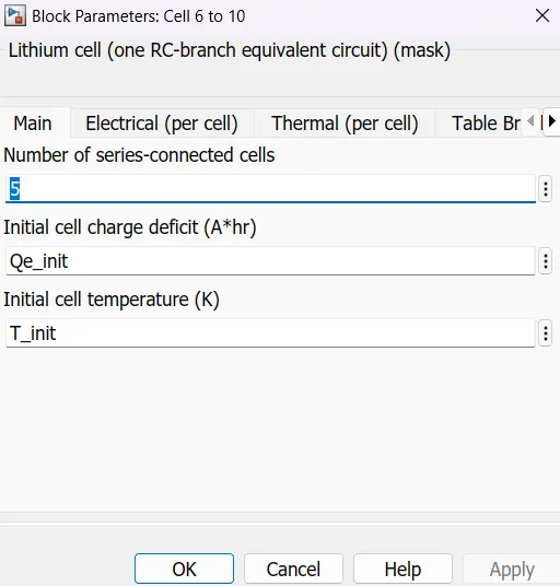
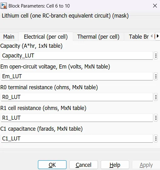
Controlled Heat Flow Rate Source:
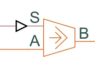
This block represents an ideal energy source in a thermal network that can maintain a controlled heat flow rate regardless of the temperature difference. The heat flow rate is set by the physical signal port S. A positive heat flow rate flows from port A to port B.
Thermal Mass:

Temperature Sensor:

- The Temperature Sensor block represents an ideal temperature sensor, that is, a device that determines the temperature differential measured between two points without drawing any heat.
- Connections A and B are thermal conserving ports that connect to the two points where temperature is being monitored. Port T is a physical signal port that outputs the temperature differential value.
Conductive Heat Transfer:
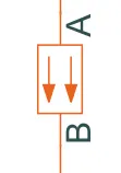
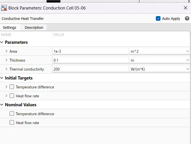
- This block models heat transfer in a thermal network by conduction through a layer of material. The rate of heat transfer is governed by Fourier's law and is proportional to the temperature difference, material thermal conductivity, area normal to the heat flow direction, and inversely proportional to the layer thickness.
- The conduction is done from the 2sets of blocks, 1 block is used for 04-05 and the other is used for cells 05-06.
Convective Heat Transfer:
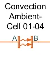
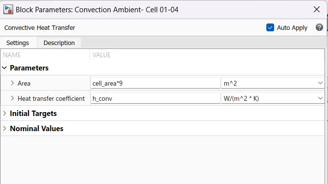
- The convective heat transfer block models heat transfer in a thermal network by convection due to fluid motion. The rate of heat transfer is proportional to the temperature difference, heat transfer coefficient, and surface area in contact with the fluid.
- This block is used for 1-4 cells and 6-10 cell for stimulating the effect of heat transfer by convection.
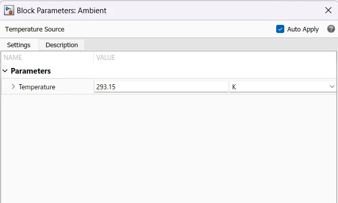
Temperature Source :
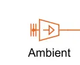
This block represents an ideal energy source in a thermal network that can maintain a constant absolute temperature at the port regardless of the heat flow rate.
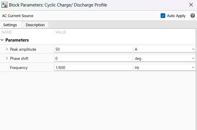
AC Current Source:
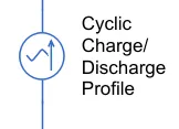
- The ideal AC current source maintains the sinusoidal current through it, independent of the voltage across its terminals.
- The peak amplitude is set to 50A for cyclic charge and discharge.
RESULTS
1 .Test 1 at 293.15K ..ie 20 °C Ambient Temparature (K)
Temperature VS Time
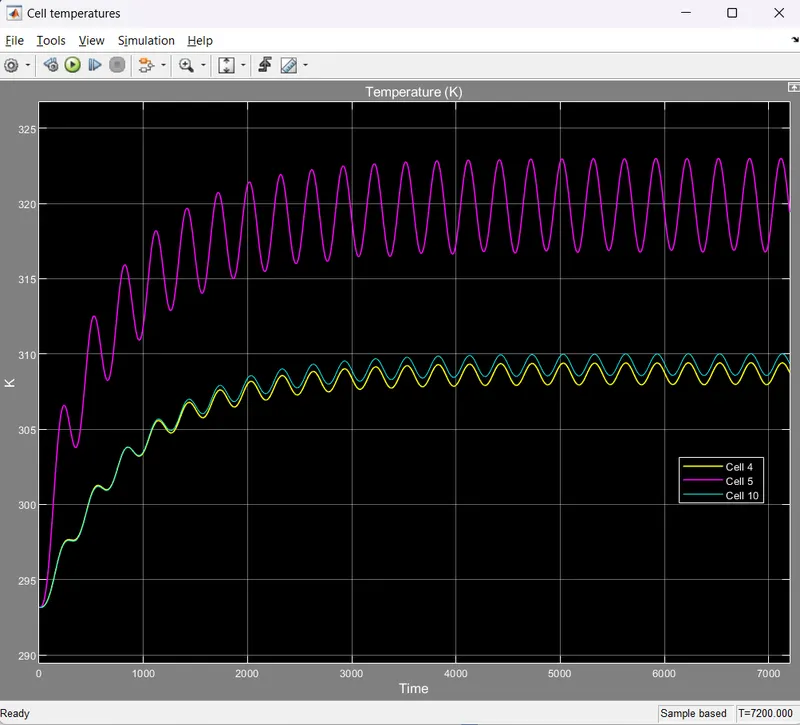
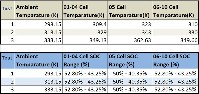
- In the test 1 the ambient temperature is set to 293.15 k ie 20 °C, the cells 1-4 temperature is 309.4 K and 6-10 cell temperature is 310 K
- Whereas the temperature of fault cell 5 is obtained as 323 K.There is a difference of nearly 13K.
- This shows that the fault cell is being heated up fastly and higher than the normal cells.
SOC VS Time:
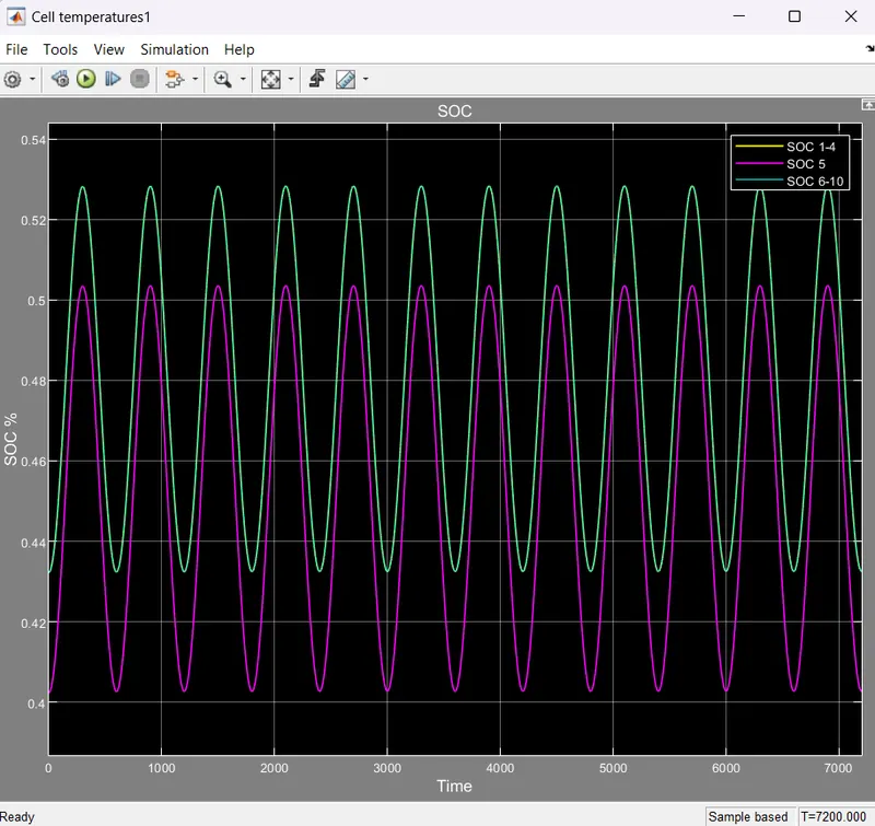
- From the graph we can see that both the good set of batteries soc plots coinsides eachother and appear as single wave signal.
- The max SOC is obtained as 52.8% while charging and while discharging it is 43.25%.
- Whereas the fault cell 5 SOC is found to be less than the other which is found a max SOC of 50% and while discharging it goes to 40.35% SOC.
- This shows that when the good cell can reach to a charging SOC of 52.8% the fault cell can only reach to 50%.Similarly in case of dicharging when the good cell can discharges up to 43.25% the fault cell discharges quiclky and reach 40.35%
2 .Test 1 at 313.15K ..ie 20 °C Ambient Temparature (K)
Temperature VS Time
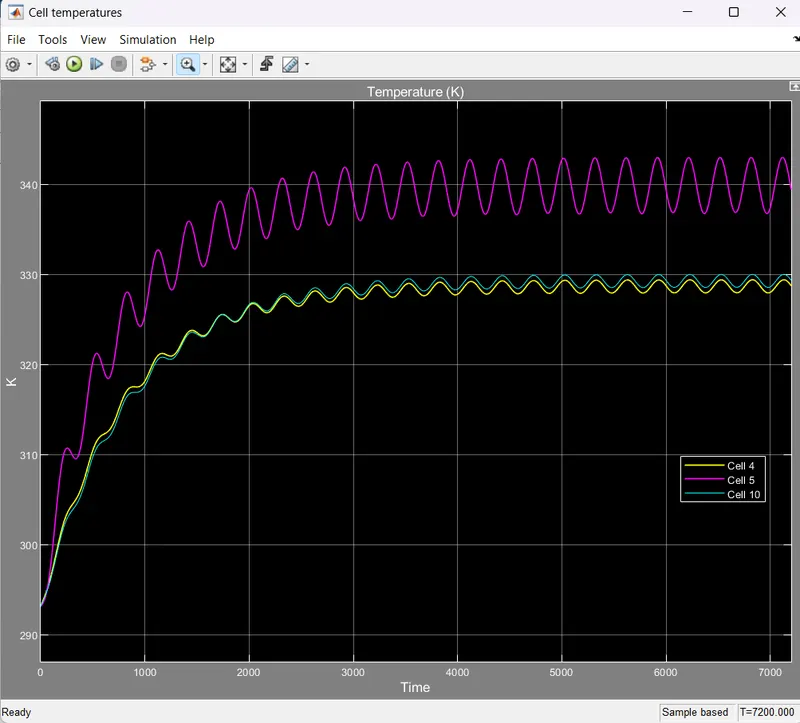
- In the test 2 the ambient temperature is set to 313.15 k ie 40 °C, the cells 1-4 temperature is 329 K and 6-10 cell temperature is 330 K.
- Whereas the temperature of fault cell 5 is obtained as 343 K.There is a difference of nearly 13K.
SOC VS Time:
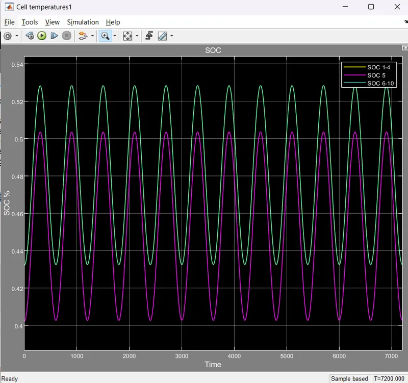
- From the graph we can see that the results are exactly similar to that of test 1.
- The max SOC is obtained as 52.8% while charging and while discharging it is 43.25%.
- Whereas the fault cell 5 SOC is found to be less than the other which is found a max SOC of 50% and while discharging it goes to 40.35% SOC.
2 .Test 1 at 313.15K ..ie 20 °C Ambient Temparature (K)
Temperature VS Time
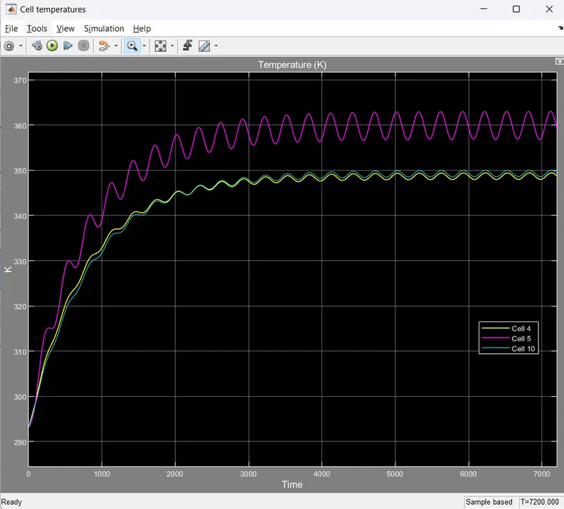
- In the test 3 the ambient temperature is set to 333.15 k ie 60 °C, the cells 1-4 temperature is 349.13 K and 6-10 cell temperature is 349.66 K.
- Whereas the temperature of fault cell 5 is obtained as 362.63 K.There is a difference of nearly 13K.
SOC VS Time:
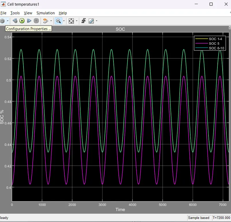
- From the graph we can see that the results are exactly similar to that of test 1 and test 2.
- The max SOC is obtained as 52.8% while charging and while discharging it is 43.25%.
- Whereas the fault cell 5 SOC is found to be less than the other which is found a max SOC of 50% and while discharging it goes to 40.35% SOC.
CONCLUSION
Modelled a 10 cell series lithium ion battery model and simulate the thermal effects and compare life cycle performance at various temperatures, charge & discharge rates using MATLAB.
REFERENCE
https://in.mathworks.com/help/simscape/ug/lithium-ion-battery-pack-with-fault.html