Wiring harness routing & packaging Rules Week 3 Challenge
AIM
1. To define P Clamp as Electrical support using Electrical Part design Workbench and Define all the necessary properties.
2. To define Back shell cad data as Electrical back shell using Electrical Part design Workbench and Define all the necessary properties.
3. To create Corrugated tubes & Add them in Catalogue under “Slit COT” family.
PROCEDURE
1. P Clamp
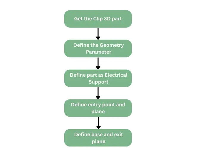
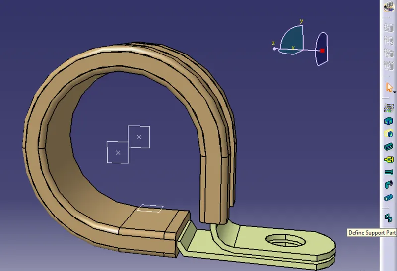
Step 1 : Open the 3D part in Mechanical part design and create points at center of entry and exit planes, and then create planes at this entry and exit plane and at the base.
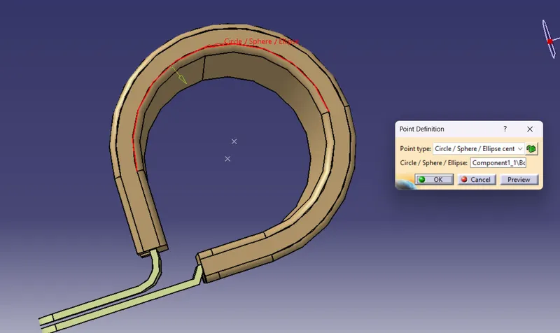
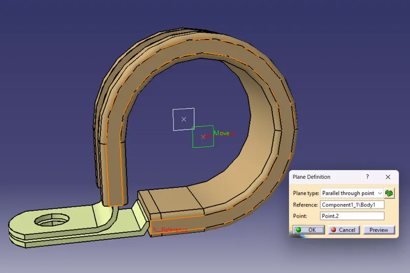
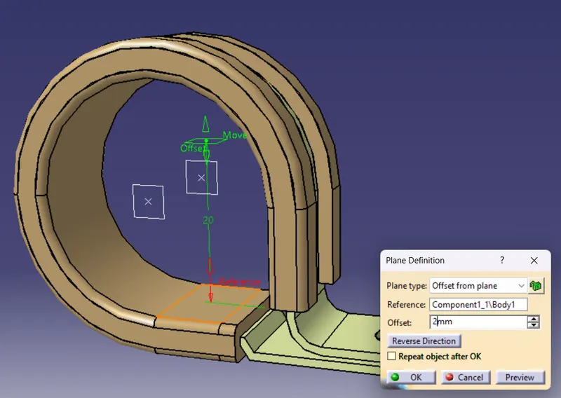
The entry and exit planes were created by selecting the corresponding entry and exit planes and corresponding entry and exit points.
The base plane is set for 2 mm offset.
Step 2 : Define the part as Electrical Support part.
Switch to electrical part design and click on 'Define Support part' and then select the model part.
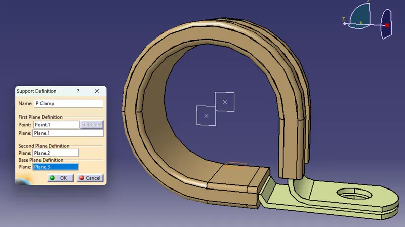
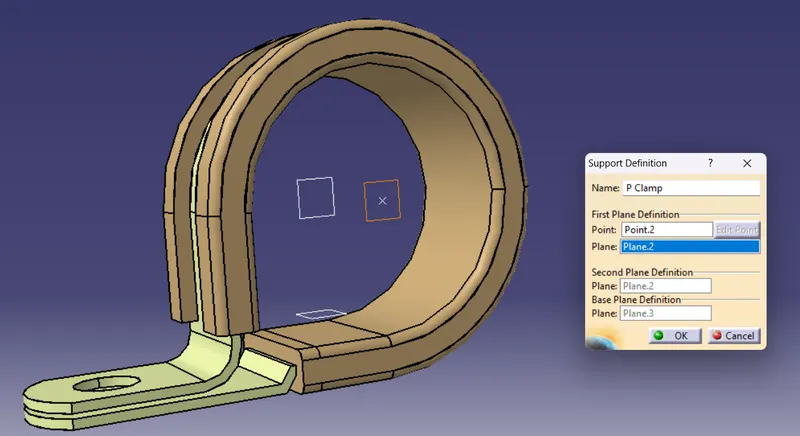
For the Clip we can use either side for entry and exit, so we need to define the entry and exit from the both sides.
2. Back shell
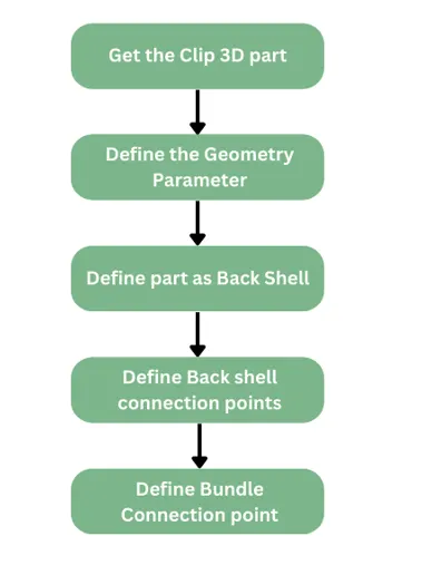
Step 1 : Open the 3D part in Mechanical part design and create points at center Bundle entry and the connector mating face.
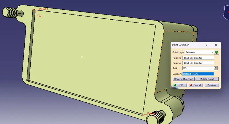
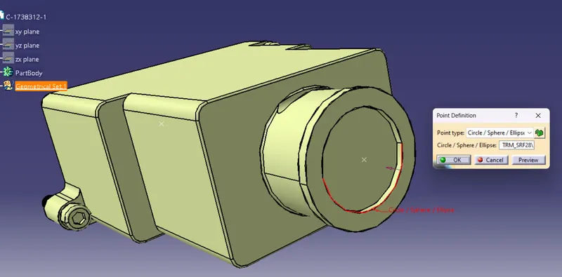
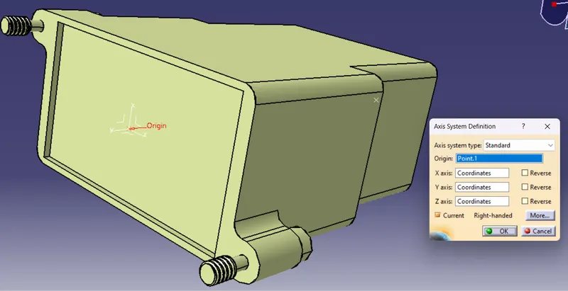
Step 2 : Define the axis system at the Connector connection point.
Step 3 : Switch to electrical part design and define the part as Back shell
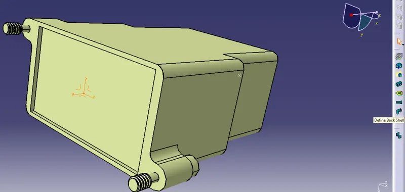
Select the define Back shell command and click on the part.
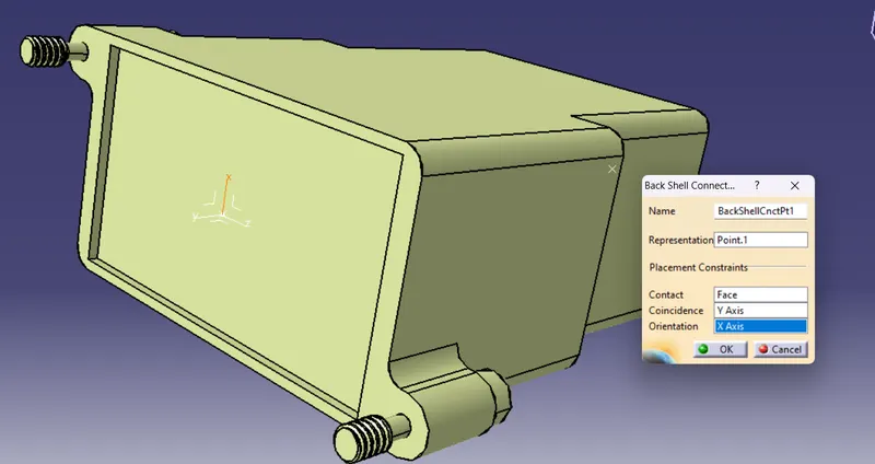
Step 4 : Define Back shell connection point
Representation - The point created at the center of the connector connection point.
Contact - Surface that is goint to mate with the connector.
Coincedence - y axis
Orientation - x axis
3. Corrugated tubes
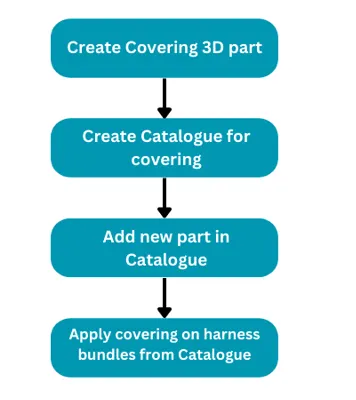
Step 1: Open electrical part design workbench and select 'Define protection part' and click on the 'part body' in the tree to define the property.
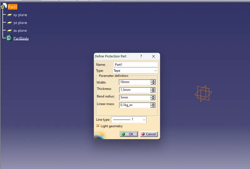
Step 2 : Define the Protection part parameters and save the model.
Name - 15mm COT
Inner diameter - 12 mm
Thickness - 1.5 mm
Bend radius - 1.5 times external diameter = 1.5 * 15 = 23 mm
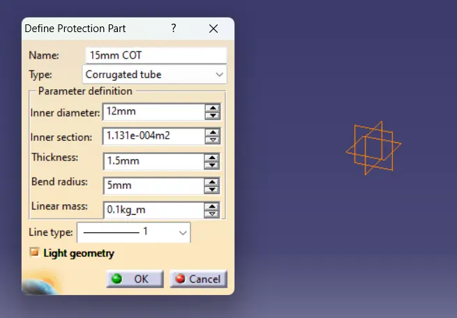
Step 3 : Create a new catalogue
Goto files -> New -> Select Catalogue document -> Click on add Family -> Give the name and select Type as 'Conduit'
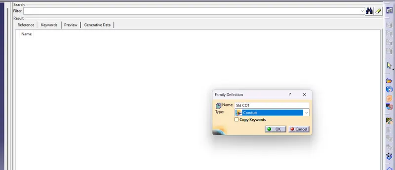
Now the calalogue is created.
Step 4 : Click on 'Store device' command and navigate to the Catalogue created and also select the family.
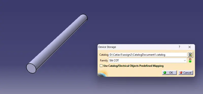
Step 5 : Again open new electrical part design workbench and select 'Define protection part' and click on the 'part body' in the tree to define the property.
Name - 20mm COT
Inner diameter - 17 mm
Thickness - 1.5 mm
Bend radius - 1.5 times external diameter = 1.5 * 20 = 30 mm
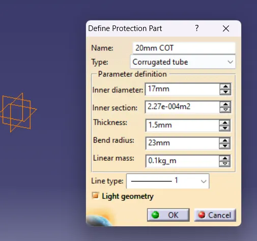
Save the model in the same location where the first tube is saved.
Step 6 : Click on 'Store device' command and navigate to the Catalogue created and also select the family.
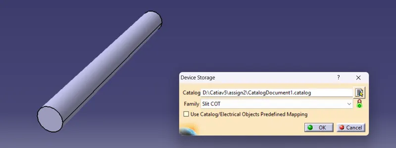
Step 7 : This method is repeated for 35mm COT, 10mm COT, 5mm COT
Name - 35mm COT
Inner diameter - 32 mm
Thickness - 1.5 mm
Bend radius - 1.5 times external diameter = 1.5 * 35 = 53 mm
Name - 10mm COT
Inner diameter - 7 mm
Thickness - 1.5 mm
Bend radius - 1.5 times external diameter = 1.5 * 10 = 15 mm
Name - 5mm COT
Inner diameter - 3 mm
Thickness - 1 mm
Bend radius - 1.5 times external diameter = 1.5 * 7 = 8 mm
CONCLUSION
- Defined P Clamp as Electrical support using Electrical Part design Workbench and Define all the necessary properties.
- Defined Back shell cad data as Electrical back shell using Electrical Part design Workbench and Define all the necessary properties.
- Created Corrugated tubes & Add them in Catalogue under “Slit COT” family.