Week 9 - Challenge 3 - Bumper
AIM
To create the Bumper Plastic component through the given Class-A surface.
PROCEDURE
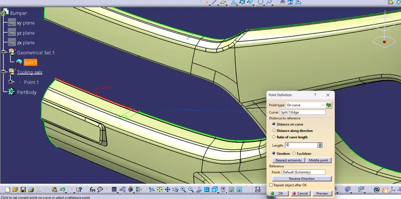
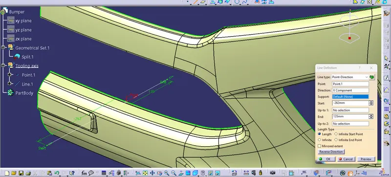
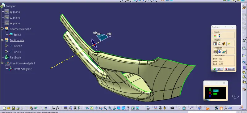
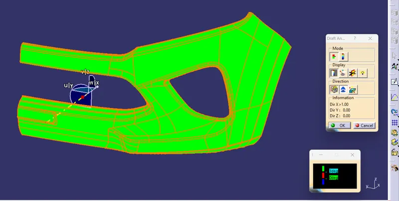
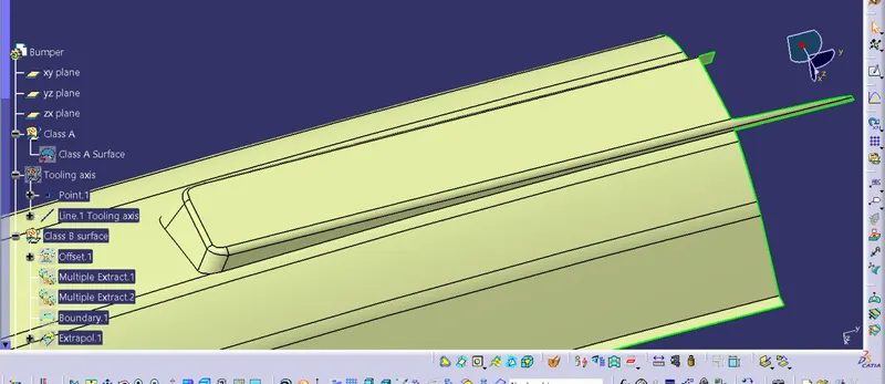
Step 1 : After opening the Class A surface, Create a Tooling axis and do the draft analysis.
- Frist create a point on the curve and then draw a line which wil be the tooling axis along the x direction.
- Then the draft analysis is carried out by placing the compass alligne with the tooling axis and locking it in place.
- Now select the surface and we can see all the surface clear the 3 degree draft.
Step 2 : Next we are going to create Class B surface from the Class A.
- First insert a 'Geometrical set' and Using 'Offset' command Offset the entire surface,here we are offsetting the surface as a whole due to the complexity of the surface.
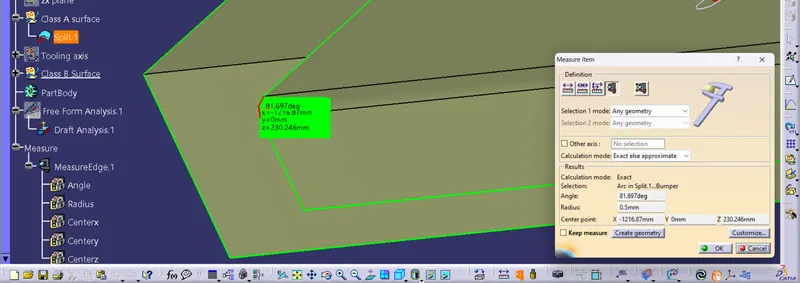
- 3 mm Offset is given for the surface.
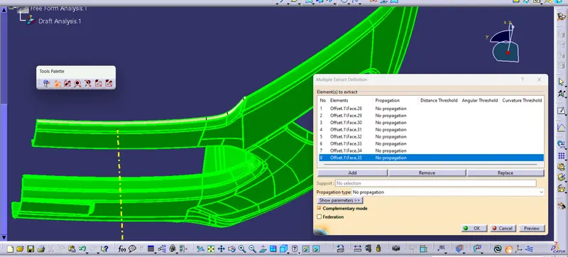
- After Offsetting we can find some of the surfaces are missing.
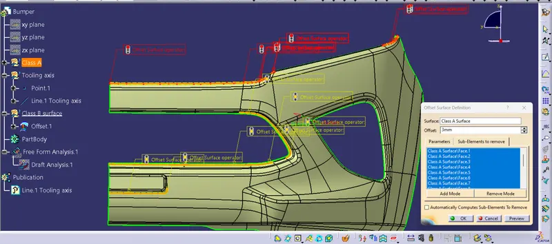
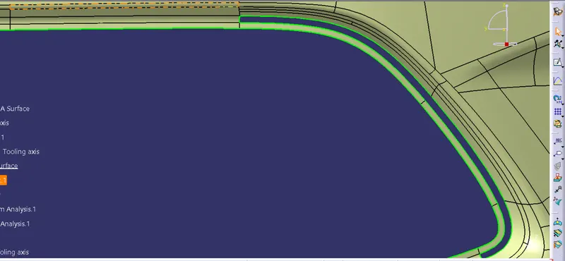
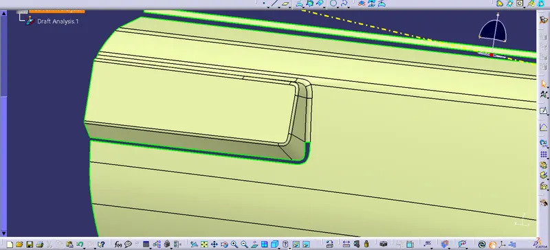
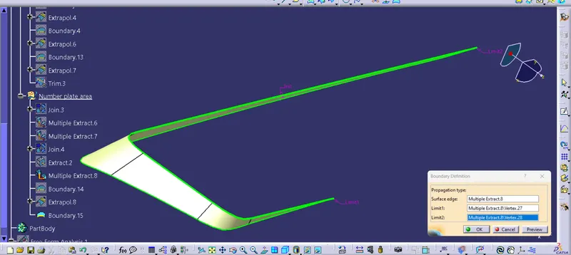
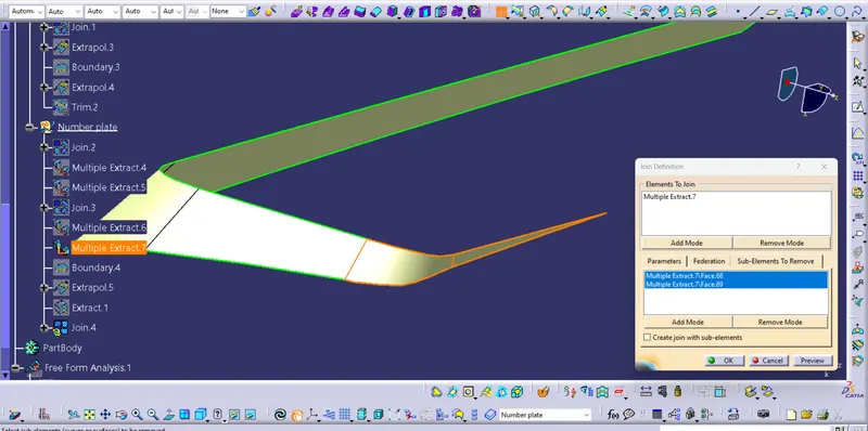
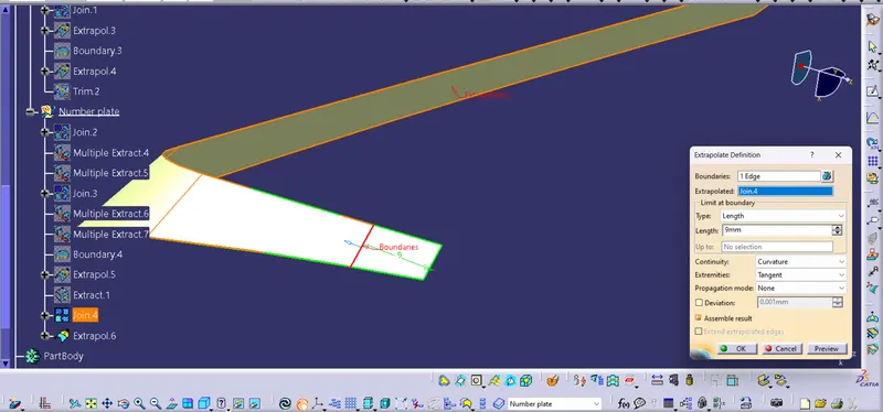
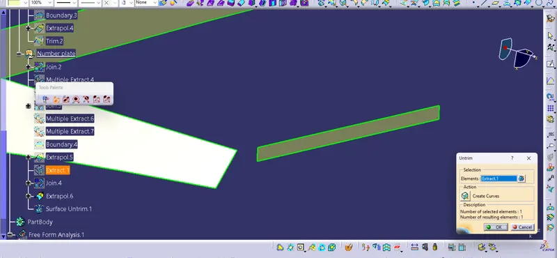
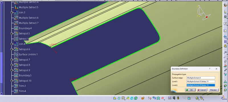
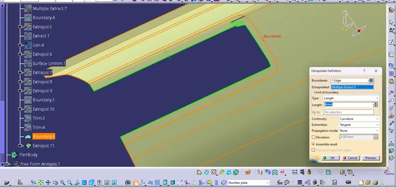
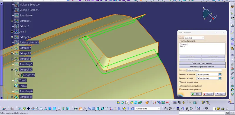
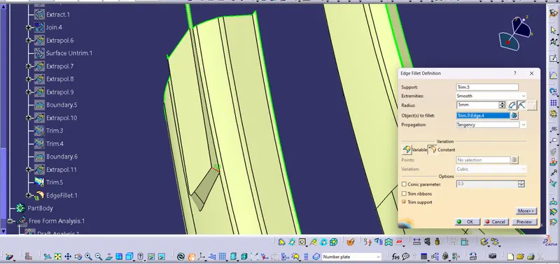
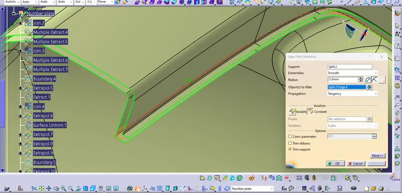
Step 3: Finding the missing surfaces/fillets and resolving them thereby completing the Class B Surface.
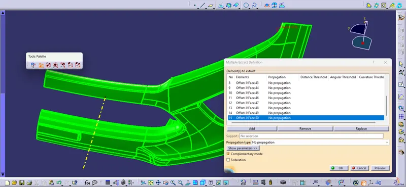
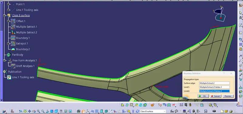
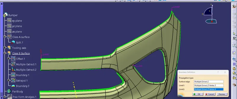
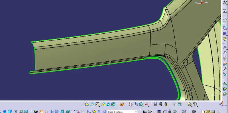
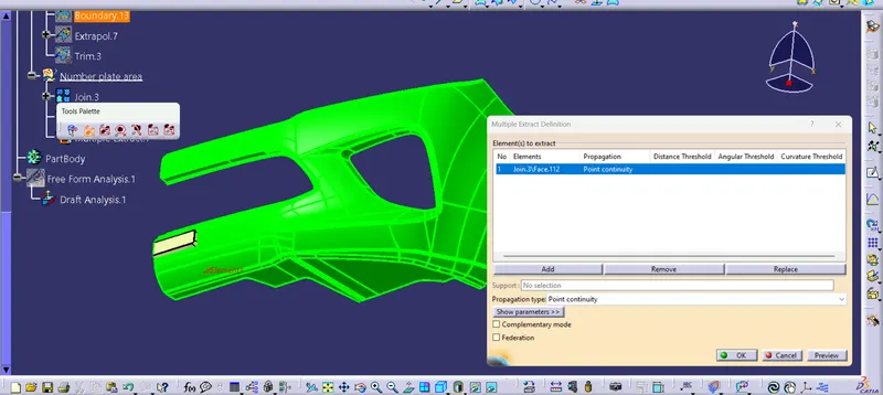
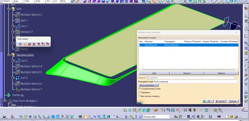
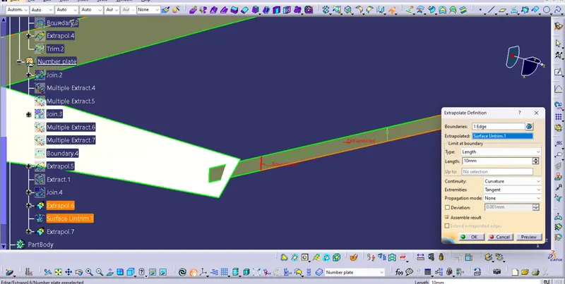
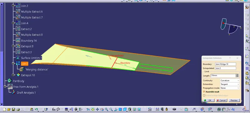
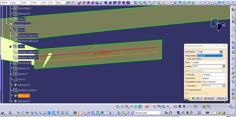
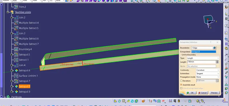
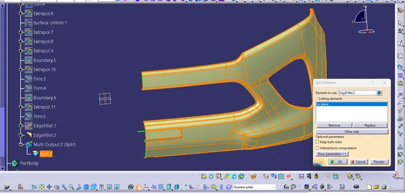
- First extract both the surface which are need to be joined
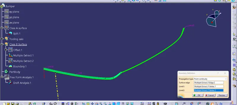
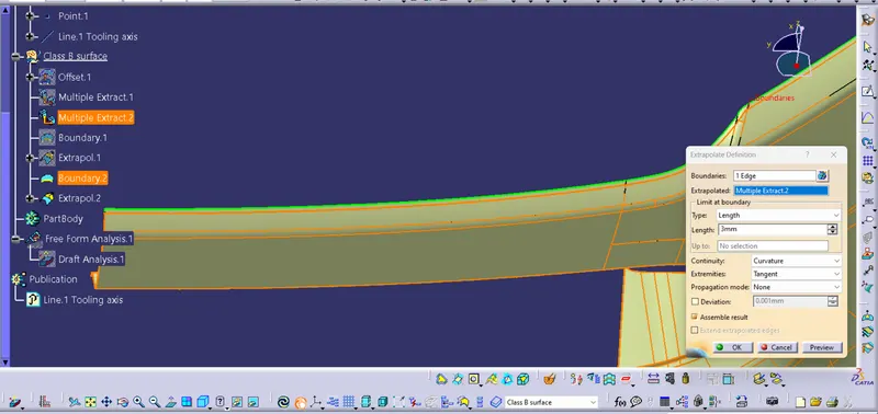
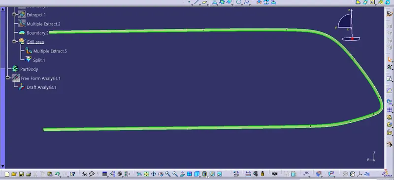
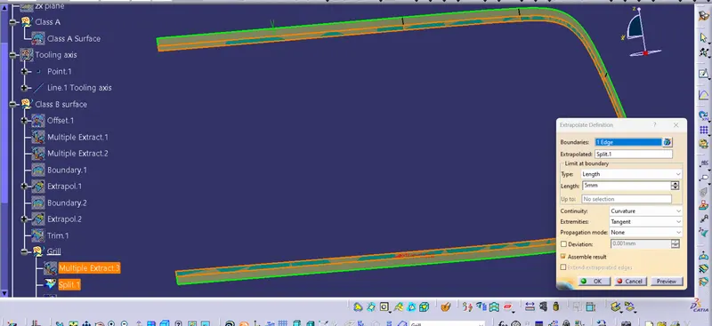
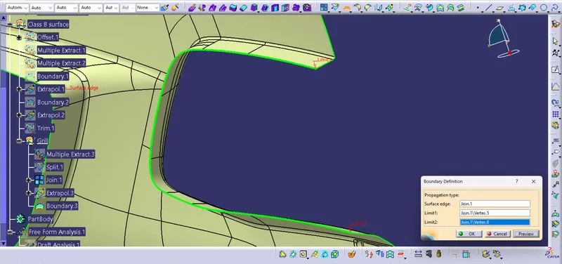
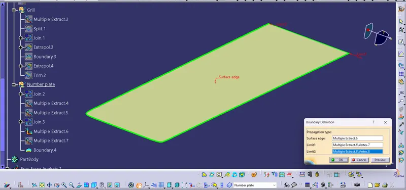
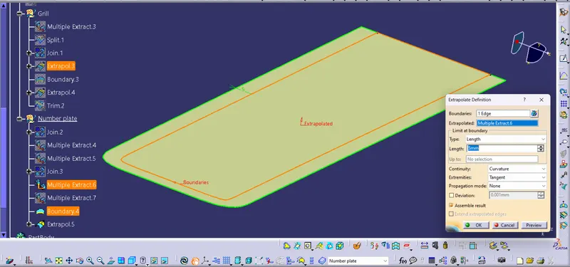
- Create a boundry of the surface which is need to be extrapolated.
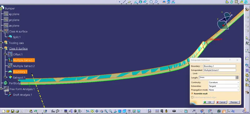
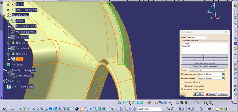
- Then extrapolate them and using trim command join the surface together.
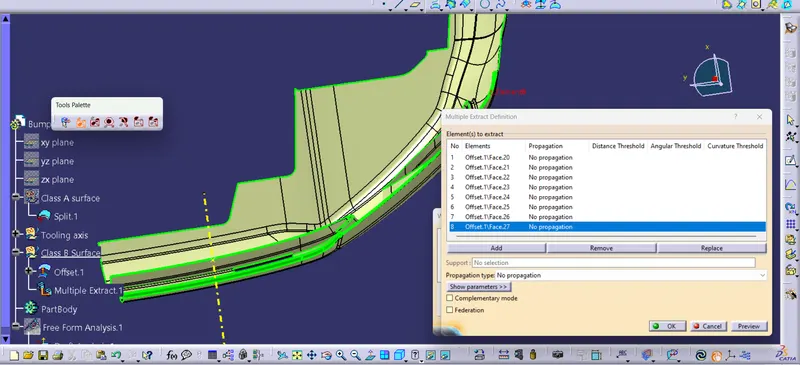
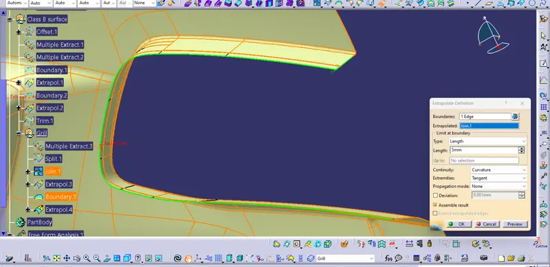
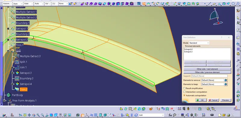
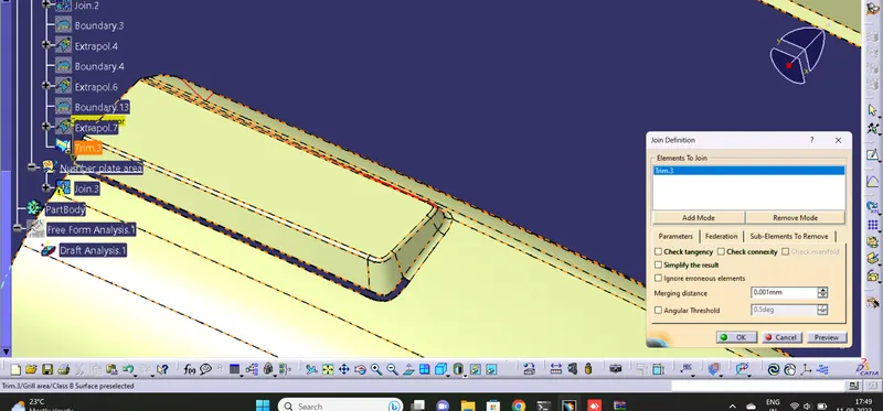
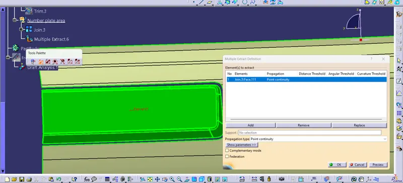
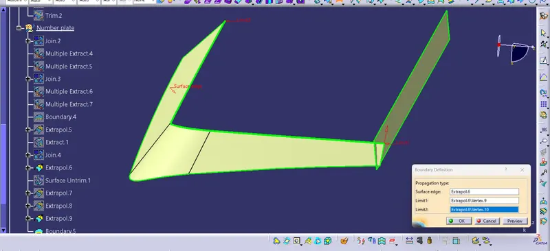
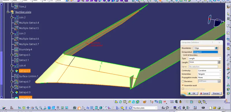
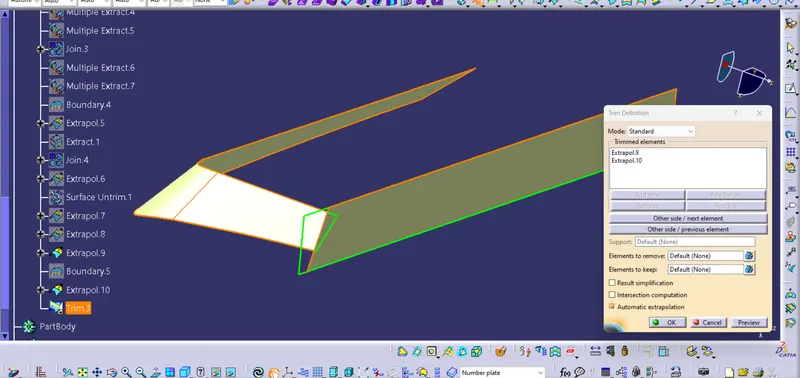
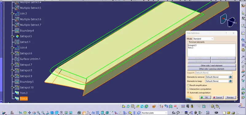

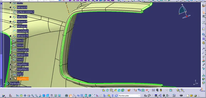
Step 4 : Now the Class B surface is completed, the next step to make the Class C surface.
- Insert a geometrical set for the class C surface.
- First create the boundry in Class A using 'Boundry' command to make the Class C surface.
- After creating the boundry use 'Sweep' command to make the surface.
- Give 3 degree drafts for surface that are perpendicular to tooling axis and 90 degree draft to surfaces parallel to tooling axis.
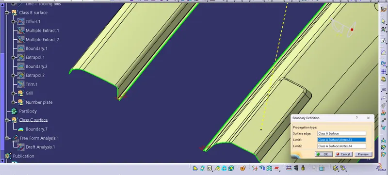
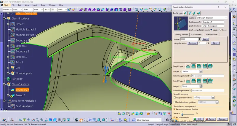
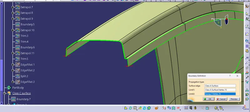
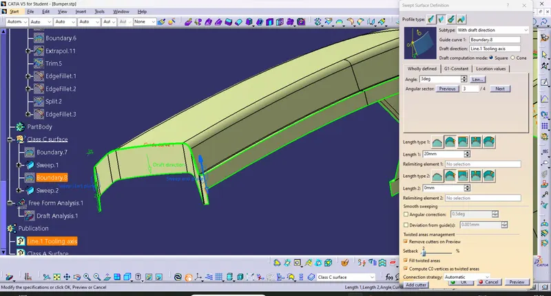
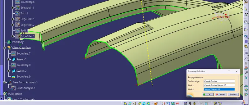
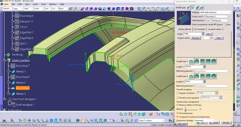
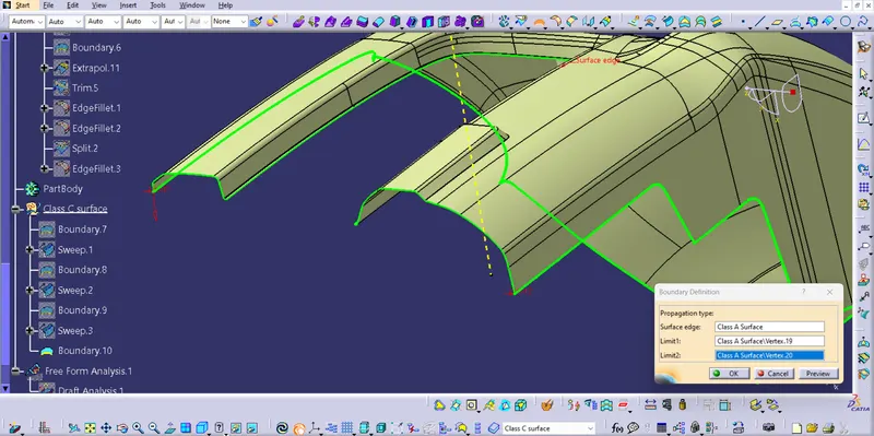
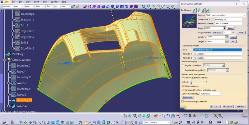
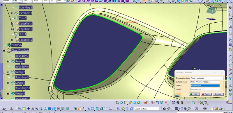
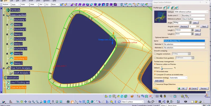
Extrapolate the sweeps and trim it to make it one.
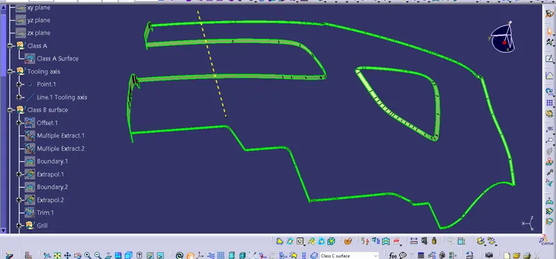
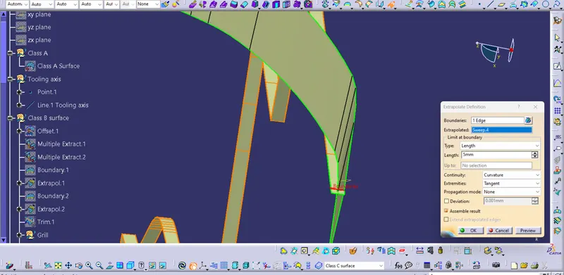
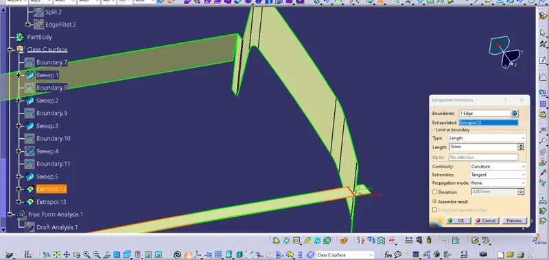
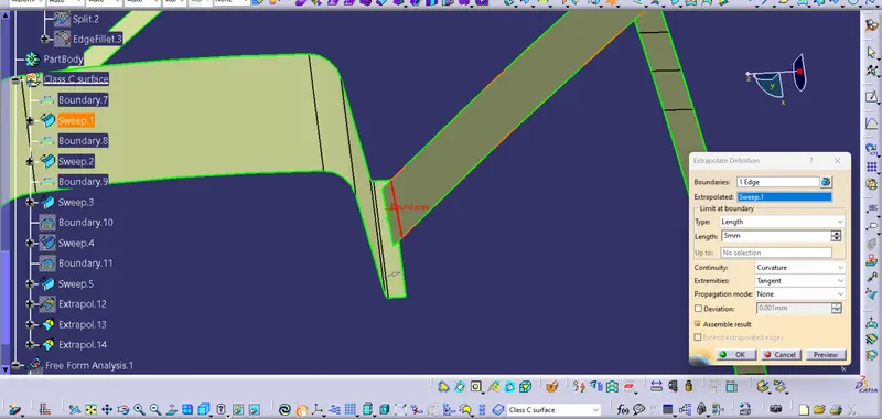
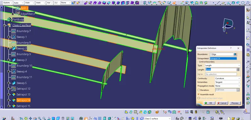
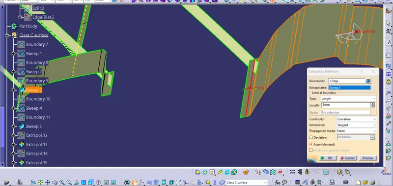
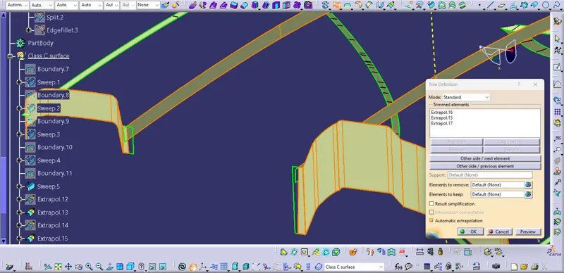
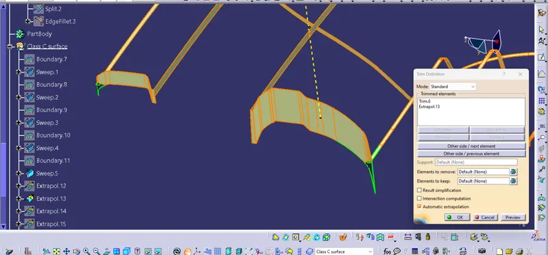
- After trimming all the sweep to one, join it with the class A surface.
- Then using the Class B surface trim it with the class A & C to get the closed surface.
- Extrapolate the requird edges to trim Class B with Class A & C
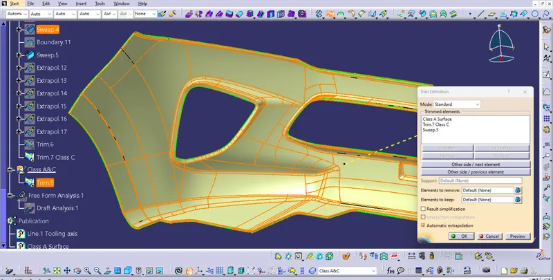
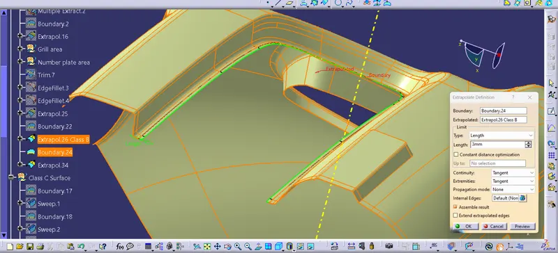
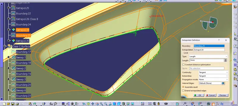
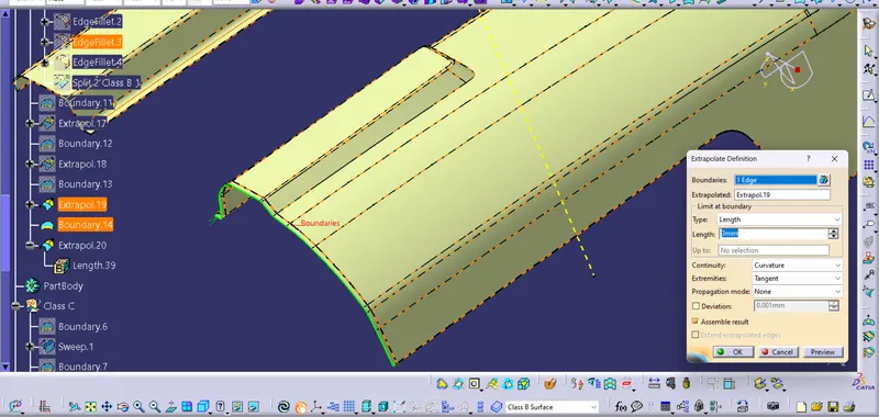
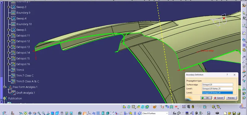
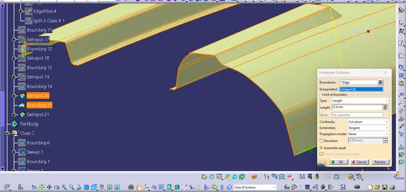
Step 5 : After completing the cutting surface B, Uaing trim command trim it with Class A&B to get the closed surface.
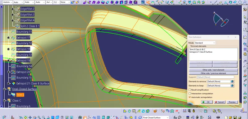
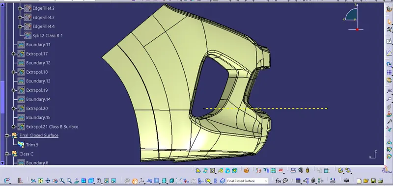
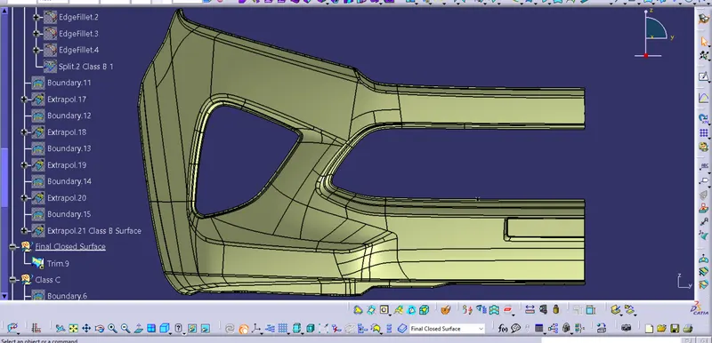
Step 6 : Making the closed surface into solid body
- Switch to part design workbench.
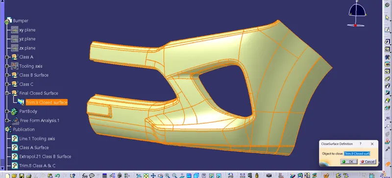
- Using 'Close Surface' command convert the closed surface into solid body.
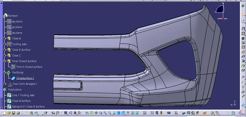
Front View
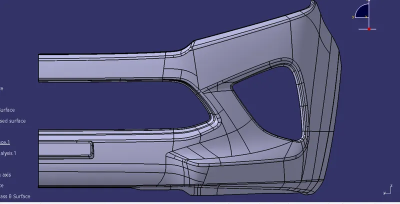
Left Side View
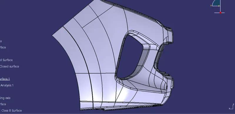
Right Side View
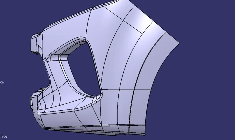
Top View
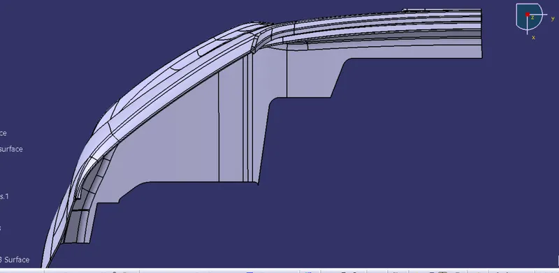
Isometric View
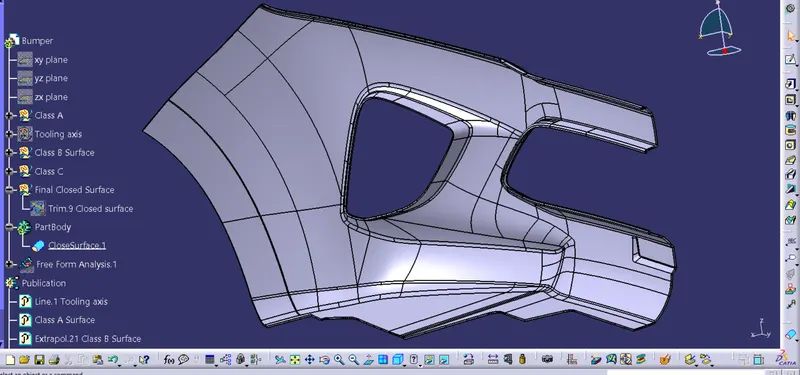
Step 7 : After completing the solid surface, next we need to conduct draft analysis.
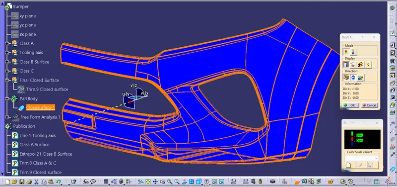
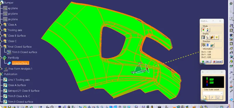
- Here in the draft analysis we found that the body is clearing 3 degree draft.
- The green towards the tooling direction shows every part is clearing the 3 degree draft whereas blue indicates negative draft.
CONCLUSION
- Created the Bumper Plastic component through the given Class-A surface.
- Conducted draft analysis