Project 1 Mechanical design of battery pack
AIM
To make a mechanical design of a battery pack with ANR26650M1-B cell and battery pack capacity of 18 kWh.
THEORY
ANR26650M1-B
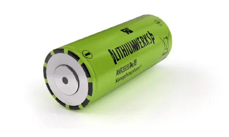
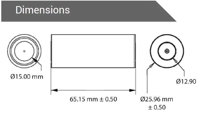
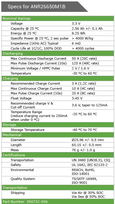
The ANR26650M1-B cell is a type of lithium-ion battery that has gained popularity in recent years due to its high performance and reliability.
The ANR26650M1-B cell has a nominal voltage of 3.3 volts and a capacity of 2.5 ampere-hours (Ah). This means that it can provide a continuous current of 2.5 amps for one hour or a higher current for a shorter period of time. The cell has a maximum continuous discharge rate of 30 amps, which is the maximum amount of current that can be drawn from the cell continuously without damaging it. It also has a peak discharge rate of 60 amps, which is the maximum amount of current that the cell can deliver for a short burst of time. The cell has a cylindrical shape, with a diameter of 26 millimeters and a length of 65 millimeters.
One of the key features of the ANR26650M1-B cell is its chemistry. The cell uses a nano-phosphate cathode material, which is a type of lithium-ion battery chemistry that was developed by A123 Systems. This material has several advantages over other types of lithium-ion batteries, including high power output, excellent thermal stability, and a long cycle life. The nano-phosphate cathode material is made up of tiny particles that are only a few nanometers in size. These particles provide a large surface area for the transfer of electrons, which allows the battery to deliver high power output. The material is also very stable at high temperatures, which helps to prevent the battery from overheating and reduces the risk of thermal runaway. Finally, the material has a long cycle life, which means that the battery can be charged and discharged many times without degrading its performance.
The ANR26650M1-B cell is used in a variety of applications that require high power output and reliability. One of the most common applications is electric vehicles, where the cell is used to power the vehicle's electric motor. The high power output of the cell allows the motor to deliver a high torque, which is necessary for accelerating the vehicle quickly. The long cycle life of the cell also ensures that the battery can withstand the demands of daily use without degrading over time.
Another application of the ANR26650M1-B cell is in grid storage systems. These systems are used to store energy from renewable sources, such as solar and wind, and then release the energy back into the grid when it is needed. The high power output and long cycle life of the cell make it well-suited for this application, as it can provide a reliable source of energy storage over a long period of time.
In conclusion, the ANR26650M1-B cell is a high-performance lithium-ion battery that is well-suited for demanding applications that require high power output and long cycle life. Its nano-phosphate cathode material provides several advantages over other types of lithium-ion batteries, including high power output, excellent thermal stability, and a long cycle life. The cell is used in a variety of applications, including electric vehicles and grid storage systems, where its high performance and reliability are critical for success.
Battery Nomenclature
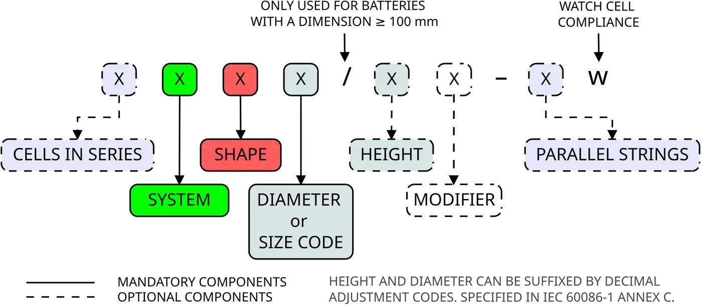
The nomenclature of battery cell names typically includes several pieces of information that describe the cell's characteristics and specifications. Here is an example of the nomenclature of the ANR26650M1-B cell:
ANR26650M1-B
- "ANR" refers to the product line or series of the battery cell. In this case, ANR stands for "A123 Nano-Phosphate Rechargeable."
- "26650" refers to the dimensions of the cell. The first two digits (26) refer to the cell's diameter in millimeters, and the last three digits (650) refer to the cell's length in tenths of millimeters.
- "M1" refers to the cell's version or revision. In this case, M1 stands for the first version of the cell.
- "-B" refers to the cell's variant or subtype. In this case, the "-B" suffix indicates a high-power variant of the ANR26650M1 cell.
BATTERY PACK CALCULATIONS
Given data
- Battery pack capacity - 18 kWh or 18000 Wh
- Cell nominal voltage - 3.3 V
- Cell Capacity - 2.5 Ah
Lets assume the total battery pack voltage required is 400 V.
So our battery pack is 18 kWh, 400 V
1. To find how much cells are need for our battery pack to meet the requirement.
Number of cells (N) = Total energy of Battery Pack/ Energy of single cell
= Total energy of Pack/ (nominal voltage*capacity ) of cell ....energy of cell [Wh] = Vnom x Ahnom.
= 18000/(3.3*2.5)
= 2182 Cells
2. To find out of 2182 cells how much is to be in Series configuration.
In series connecction-Voltage added and Current remains same.So to obtain 400 V output ,cells are connected in series.
Number of series cells (Ns) = Battery Pack Voltage / Nominal voltage of single cell
= 400 V/3.3 V
= 122 Cells (minimum)
122 cells are to be connected in series to generate 400 voltage, which has a capacity of 2.5Ah.
3. To find the number of cells to be connected in parallel
In Parallel connection-Voltage remains same and Current gets added.We need to find how many 122 cell modules are needed to be connected in parallel to ger 18000Wh.
The energy generated from single series module = 122 * Energy of single cell
= 122 * 8.25Wh = 1006.5 Wh .
Number of Cells in parallel (Np) = Total pack capacity / Capacity of single series module
= 18000/1006.5
= 17.88 -> 18 Series module (minimum)
So our battery model configuration obtained is 122S18P (122 series and 18 parallel connections).
Therefore actual number of cells in the Battery pack = 122 * 18 = 2196 Cells.
Battery pack Capacity = Number of Cells in parallel (Np)*individual cell capacity
= 18 * 2.5 = 45 Ah
The overall Capacity(Ah) of battery pack is given as 45Ah.The battery pack will supply 45 A current per hour, which is the C-rate.
The Battery Spec obtained is 45 Ah, 400 V
ENCLOSURE DIMENSION AND CONSTRUCTION
To obtain overall enclosure volume of the battery pack, we have to find the volume of single module volume consist of 122 cells in series connection and multiplied with 18 parallel connected module volume.
Outer dia of Cell D = 26 mm
Height of Cell H = 65.15 mm
Let the clearance Cl =1 mm.
With this value we need to calaulate size of battery casing.
Length of casing (L) = Number of cells in series (Ns) * (Diameter of single cell + clearance)
= 122 * (26+2)
= 122 * 28
= 3416 mm
Breadth of casing (B) = Number of Cells in parallel (Np) * (Diameter of single cell + clearance)
= 18 * (26+2)
= 18 * 28
= 504 mm
Height of Casing (Hc) = Height of cell + Thickness of metal strip (Thickness of Nickel Plated Strip - 0.12mm) + clearance
= 65.15 + 0.12 + 2
= 67.27 mm
Total Volume of the casing is = Length of casing (L) * Breadth of casing (B) * Breadth of casing (B) * Height of Casing (Hc)
= 3416 * 504 * 67.27
= 115816337 mm^3
= 0.1158 m^3
The total volume of battery pack is obtained as 0.1158 m^3 along with this the BMS and other wiring harness will be present and a room for them also need to be considered in the battery casing
Enclosures:
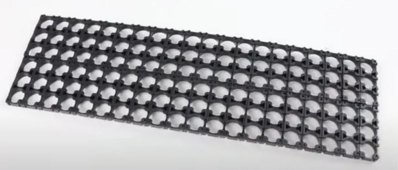
- Step 1 - The first step is to start snapping the square cell holder together.The below figure shows cell holder block.
The below image shows the insulate gasket :


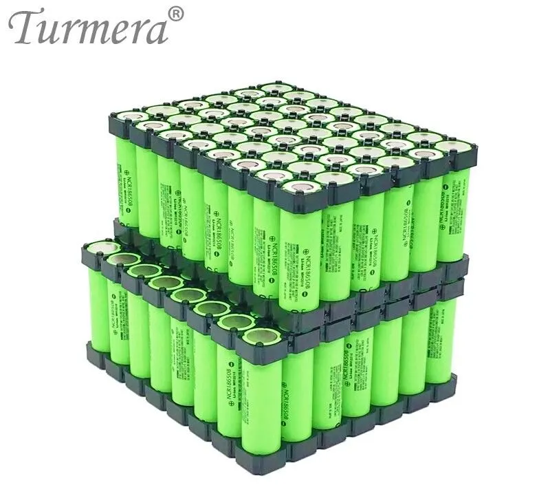
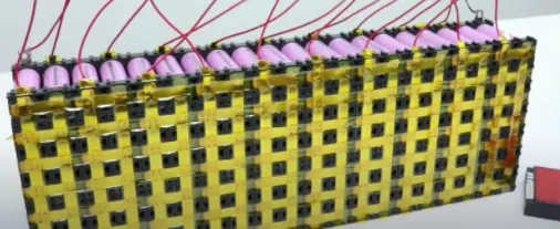
- Step 2 - Placing the cells in the holder matrix. Place all the cells in the holder and put the second holder in the place.
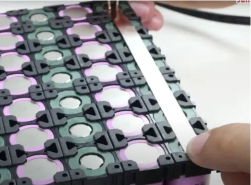
- Step 3 -Now we will be connecting the cells with nickel strips using the spot welding process. The series connection will be made by connecting the positive terminal of the cells to the negative terminal. The parallel connection will be made by connecting the same terminal.
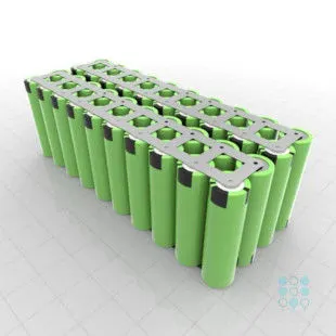
Connecting the complete matrix of the cell together.
Step 4 - Connecting the heat sink to the battery pack
 ]
]
Now we will be soldering the battery wire

Now the internal structure of the battery pack is assembled and all the terminals are connected as per the connections.
- Step 5 - Connect the balancing wire pin to the battery management system.

- Step 6 - After the battery management system, the next and final step is to place the enclosure for the battery pack.
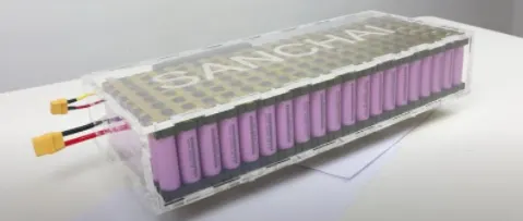
This is the final battery pack model created.
- Step 7 Battery Cabinet arrangements-
Each modules are interconnected in series or parallel according to the requirement and packed as a single large cabinet pack as shown below.
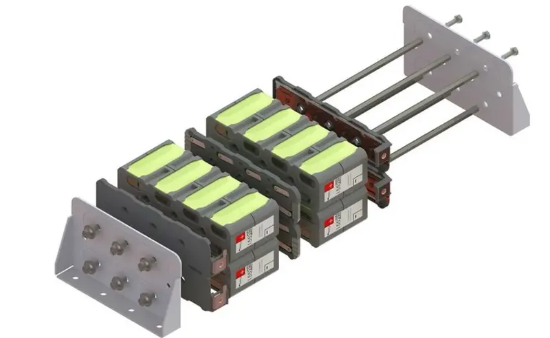
- Step 8 - Battery pack arrangement:
Finally the overall battery pack after the arrangement of all cabinet connections with enclosure looks like as shown below,
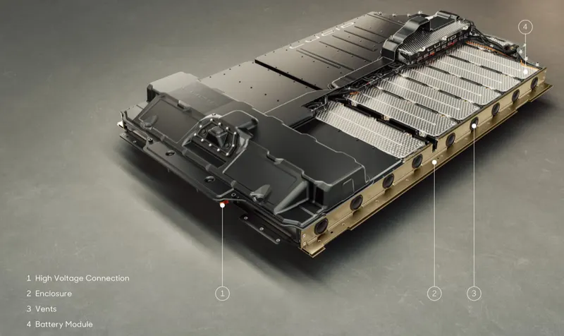
Vents holes are present with enclosure for cooling/heating the battery pack temperature according to its environment conditions.
RESULTS
Constructed a detailed battery pack drawing along with its enclosure.
REFERENCES