Week 10 - Challenge 1- Attachment Feature Creation (Ribs & Screw Boss)
AIM
- To create the rib for the Drill Handle considering the design rules.
- To create Screw boss for the Drill Handle considering the design rules.
THEORY
Tooling Axis
The term "tooling axis" refers to the orientation of the tool or cutting instrument relative to the workpiece.The tooling axis is a critical consideration in the design and manufacturing process as it directly impacts the quality, efficiency, and overall success of machining operations. Properly selecting and aligning the tooling axis helps achieve desired outcomes while minimizing defects, reducing production time, and extending tool life.
Draft Analysis
Draft analysis, also known as draft angle analysis, is a process used to evaluate the draft angles on a part's surfaces. Draft angles are the angles or tapers added to the vertical surfaces of a 3D model or part. These angles are necessary for certain manufacturing processes, such as injection molding, die-casting, or pattern-making for sand casting.
The purpose of draft angles is to facilitate the easy removal of the part from the mold or tool during the manufacturing process. Without appropriate draft angles, parts may get stuck in the mold, resulting in damage to the part or difficulties in production.
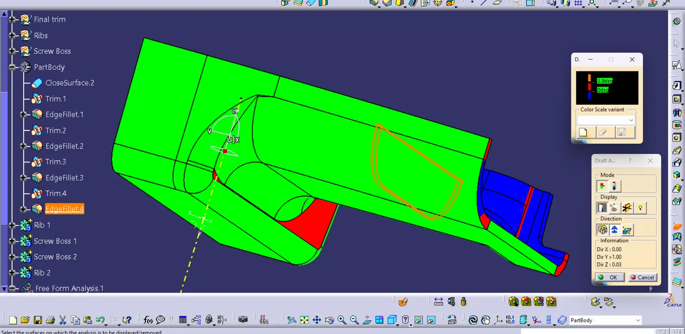
Draft analysis results are often displayed using color mapping. The surfaces are shaded based on the calculated draft angles. For example, surfaces with sufficient draft might be shown in green, while surfaces with insufficient draft (undercuts) could be shown in red.
Rib
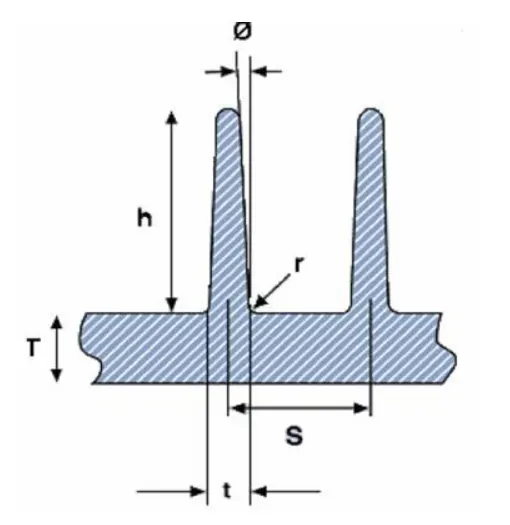
It is a thin, elongated, and often structural feature that extends from a surface of a part. Ribs are commonly used to add strength, stiffness, or other functional characteristics to a component without significantly increasing its overall weight or material usage. They are particularly useful when designing parts that need to withstand loads, vibrations, or other stresses.
General Guidelines for Bosses:
- Draft - 0.5 degrees on the walls of boss
- Thickness - Typically 40% * of the nominal wall at the base.
- Height to Diameter Ratio - 3:1
- Height - <= 5* wall thickness
- Rib fillet Radii - 0.25mm maximum radii.
- Rib thickness at Top - >= 0.75 mm
- Rib root thickness - +- 30% of wall thickness
- Spacing(S) - >=3T for steel and >=2T is preferred
Screw Boss
A "screw boss," also known simply as a "boss," is a raised, cylindrical feature on the surface of a part or component that serves as a mounting point for a screw, bolt, or other fastener. It's designed to provide a threaded hole into which a screw can be inserted, securing the component in place or allowing for the attachment of other parts. Screw bosses are commonly used in various industries, including manufacturing, engineering, and product design.
General Guidelines for Bosses:
- Draft - 0.5 degrees on the walls of boss
- Thickness - Typically 40%* of the nominal wall at the base.
- Height to Diameter Ratio - 3:1
- Radii - 0.25mm maximum radii.
PROCEDURE
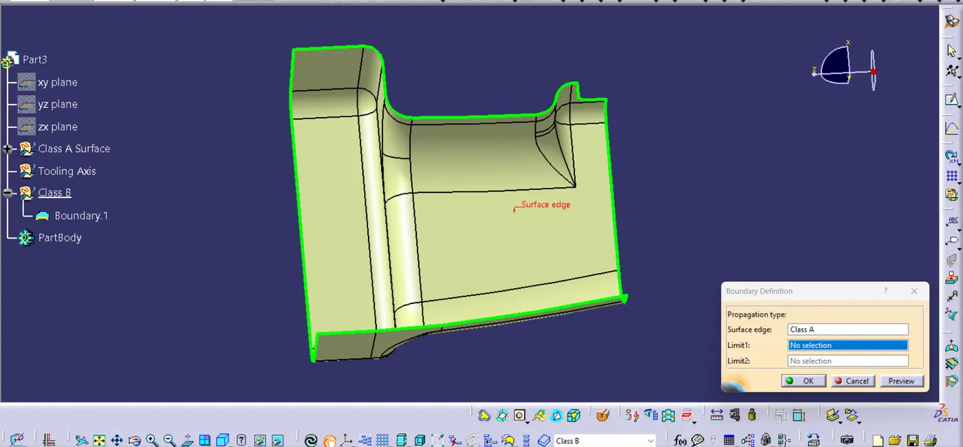
Step 1 : Create new geometrical set for adding the Tooling axis and B surface .Examin the class A surface for continuity and then publish the Class A surface.
Step 2 : Creating tooling axis
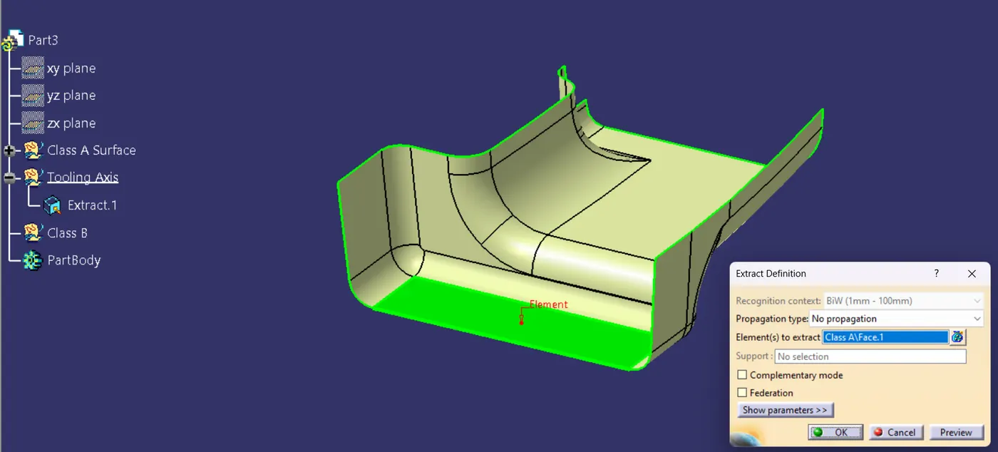
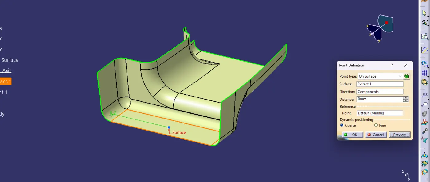
- Using the given class-A surface with the extract command extract the base surface and create a midpoint on the extracted surface.
- Insert a new axis system with respect to the point created.
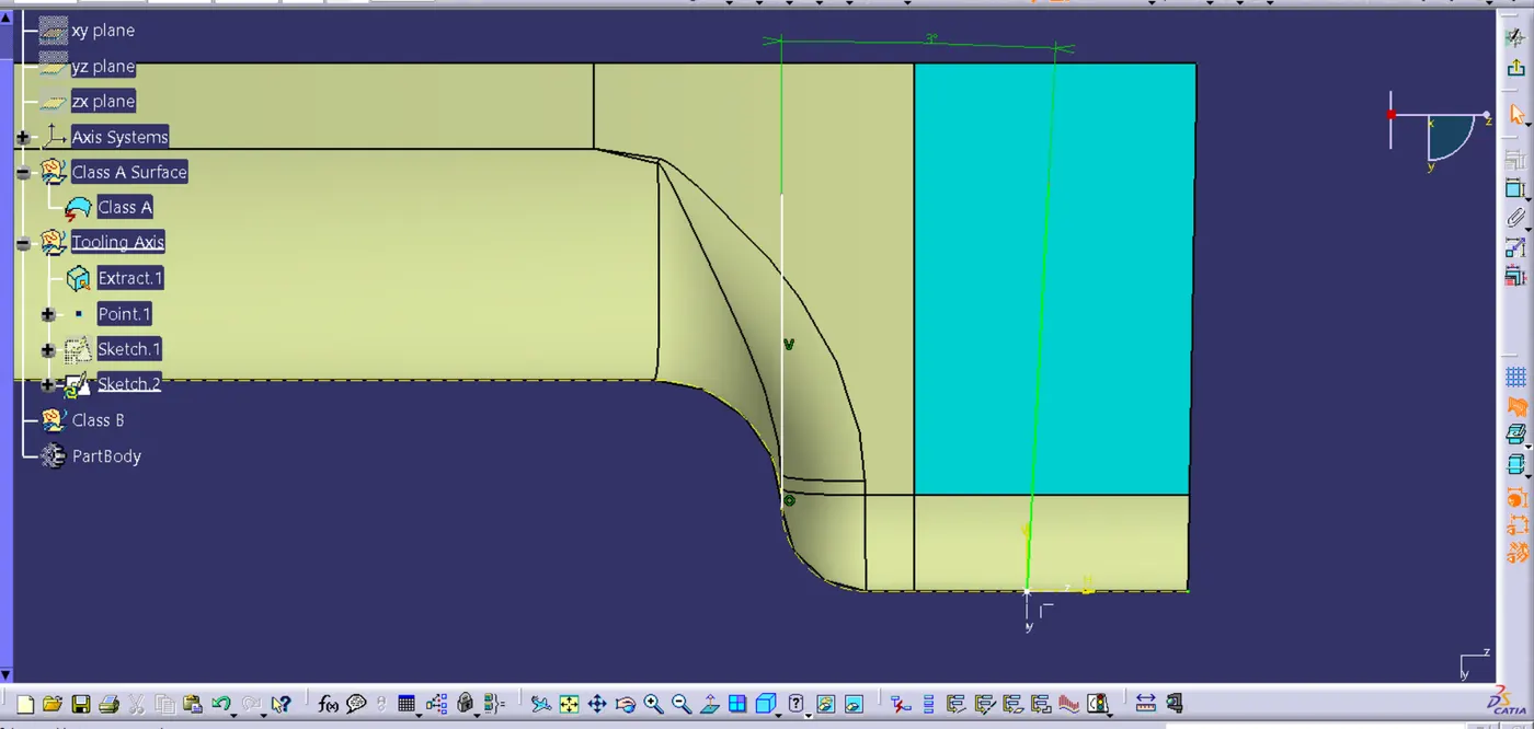
- Create a positioned sketch on the y-z plane and using the project 3D element, project the wall faces on the y-z plane.
- Then draw2 lines and which coincide with projected faces.
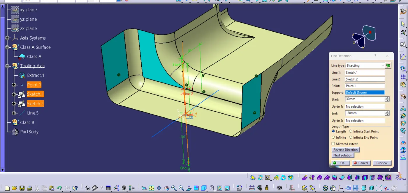
- Using the two lines a bisecting line is made.
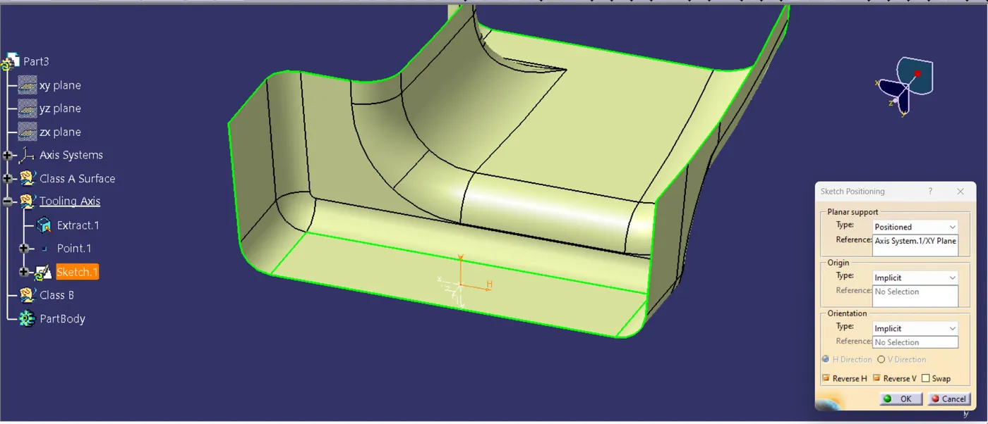
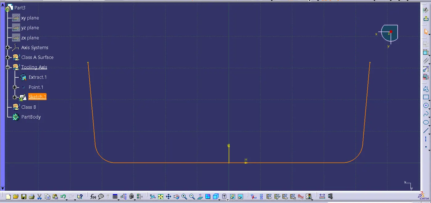
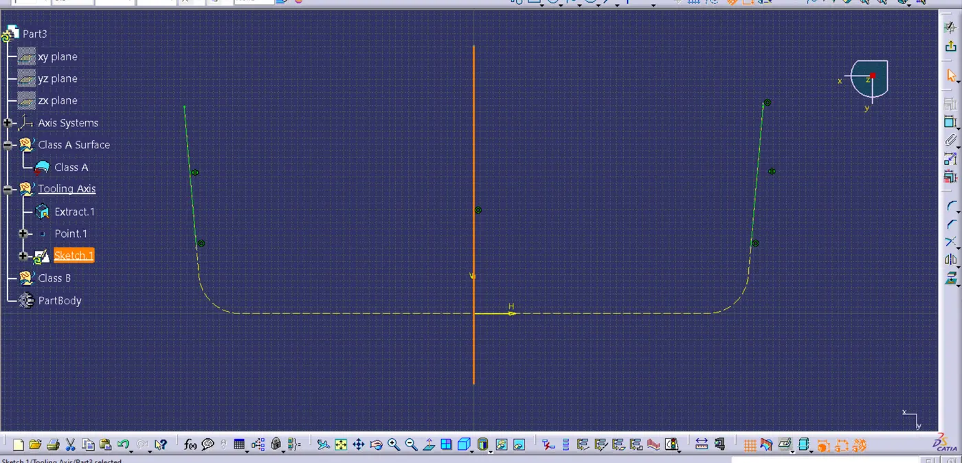
- Now we have to make an intersection line along the -z direction, create a sketch on the y-z plane and now we have face only on one side. Create an intersection or project the surface and create on line on it which coincide with wall.
- Since we have only one wall for the other wall create a line on the point we created earlier and make it at an angle 6 degree with the face, further editing on the angle is done after doing the draft analysis.
- Now we will get two lines,by bisecting these two lines we will get the 'Main tooling axis'.
- After getting the tooling axis publish it.
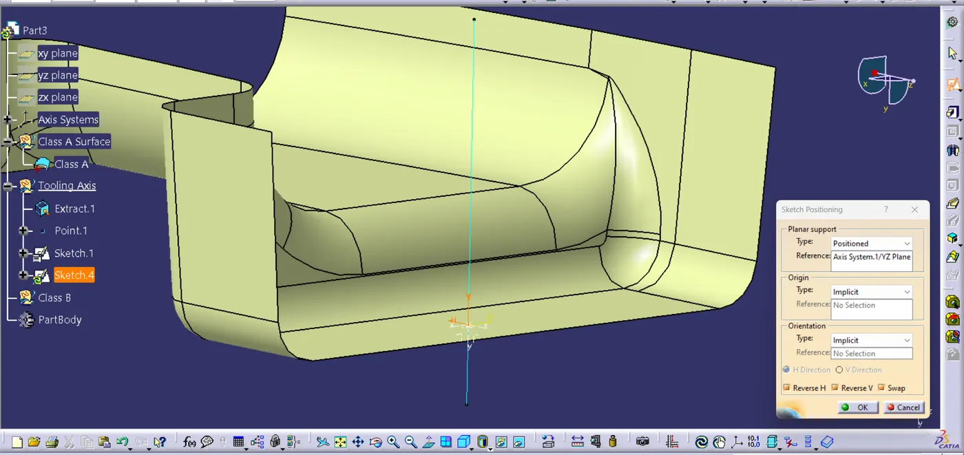
Step 3 : Now conduct the draft analysis
- Draft analysis is done after determining the tooling axis, draft analysis is used to check whether the minimum draft (3 degrees) is maintained or not.
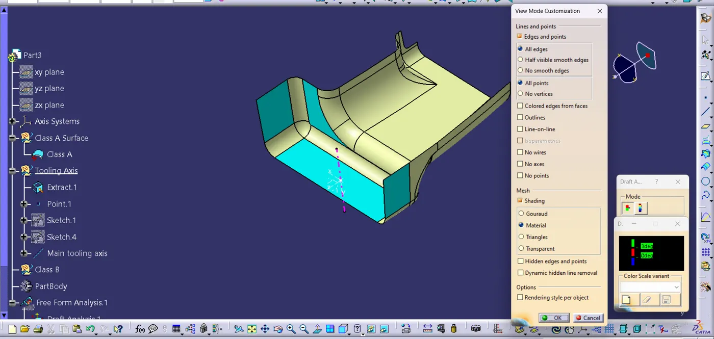
- Change the view mode of the component to be in customized parameter mode and then select the shading mode as materials.
- Then open the featured draft analysis tool from the insert menu.
- Then click on use the compass to define the current drafting direction and then drag and align the compass on the Tooling axis.
- Then lock the draft direction and perform draft analysis by clicking on the component.
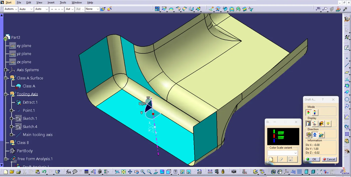
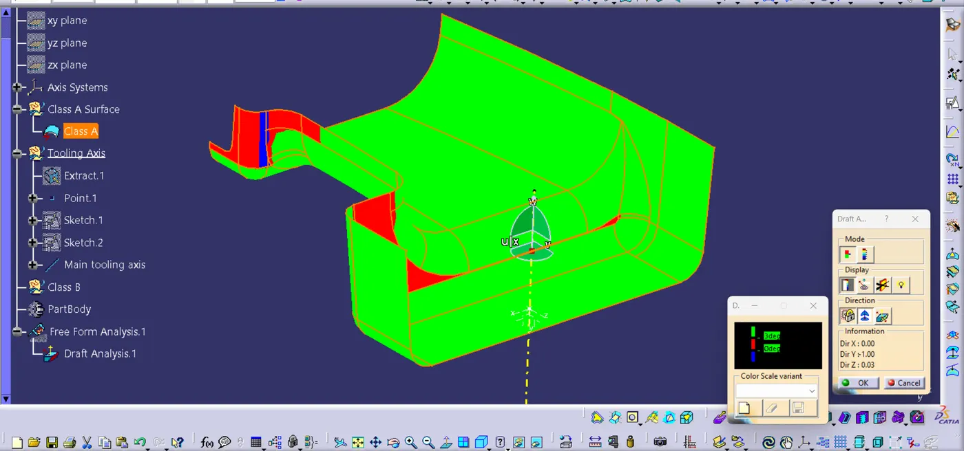
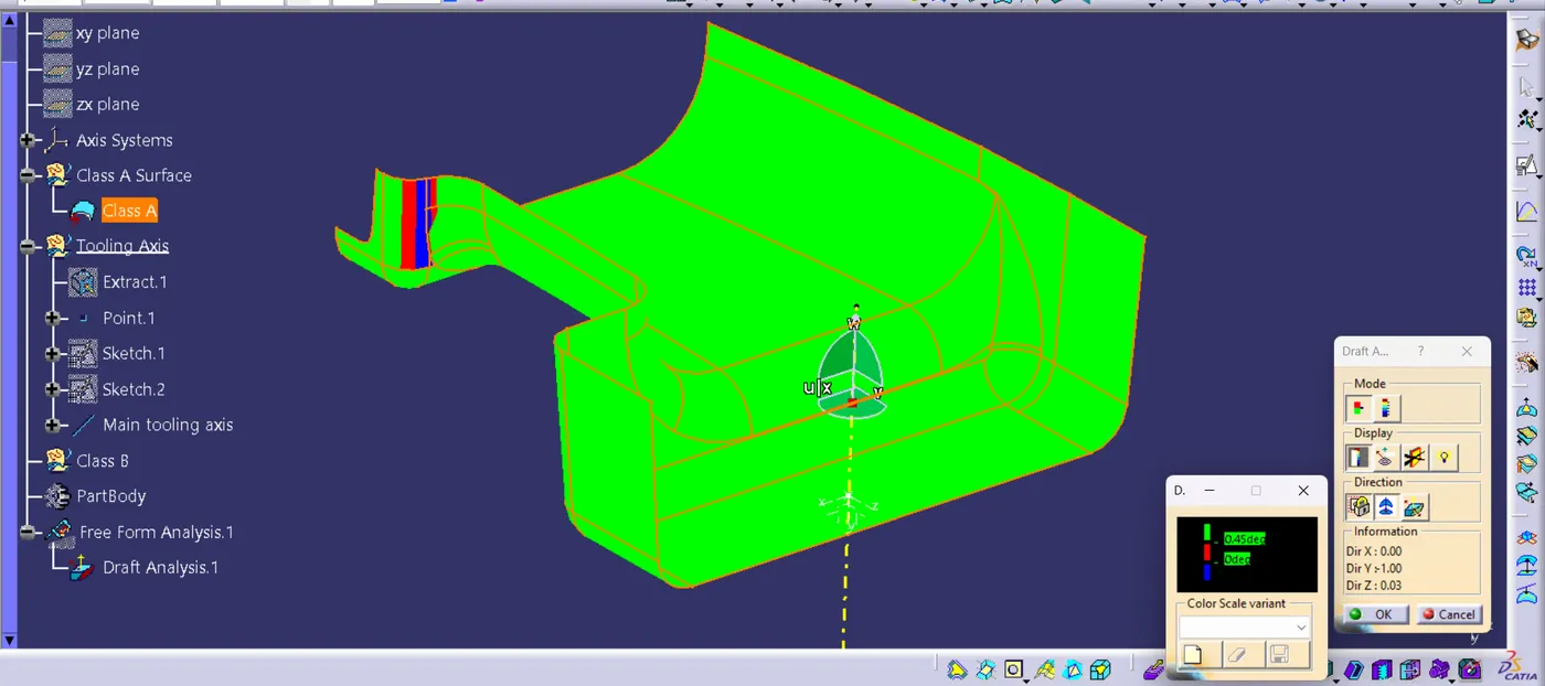
- When the draft analysis is carried out it is found that most of the areas are clearing the draft angle of 3 degree.
- But there are faces that dosent clear 3 degree draft.
- Further changes in the tooling axis is making the sitituation more worse so the design is requested to change making it clear 3 degree mimimum draft.
- Even after reducing to 0.45mm the draft is not cleared completely
Step 4 : Making the class B surface using Offset command
- Offset the class A surface 2.5 mm, which is the thickness of the part body.
- After offsetting check wheather all surfae are present else clear the faces using 'fill' command.
- Using extent command extrapolate the boundries of the surface inorder to trim the class B with Class A & C
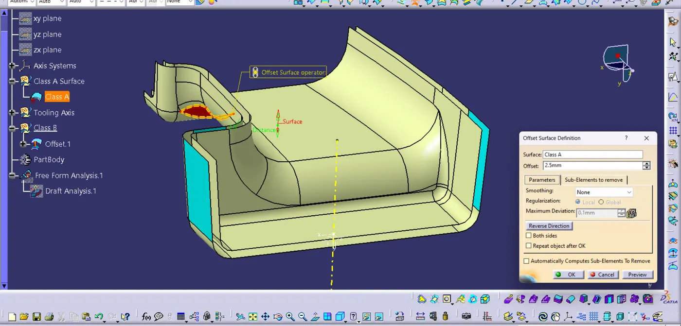
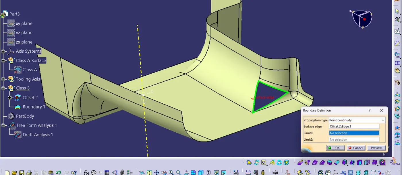
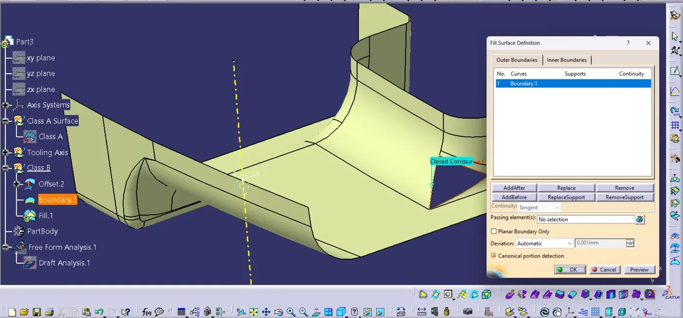
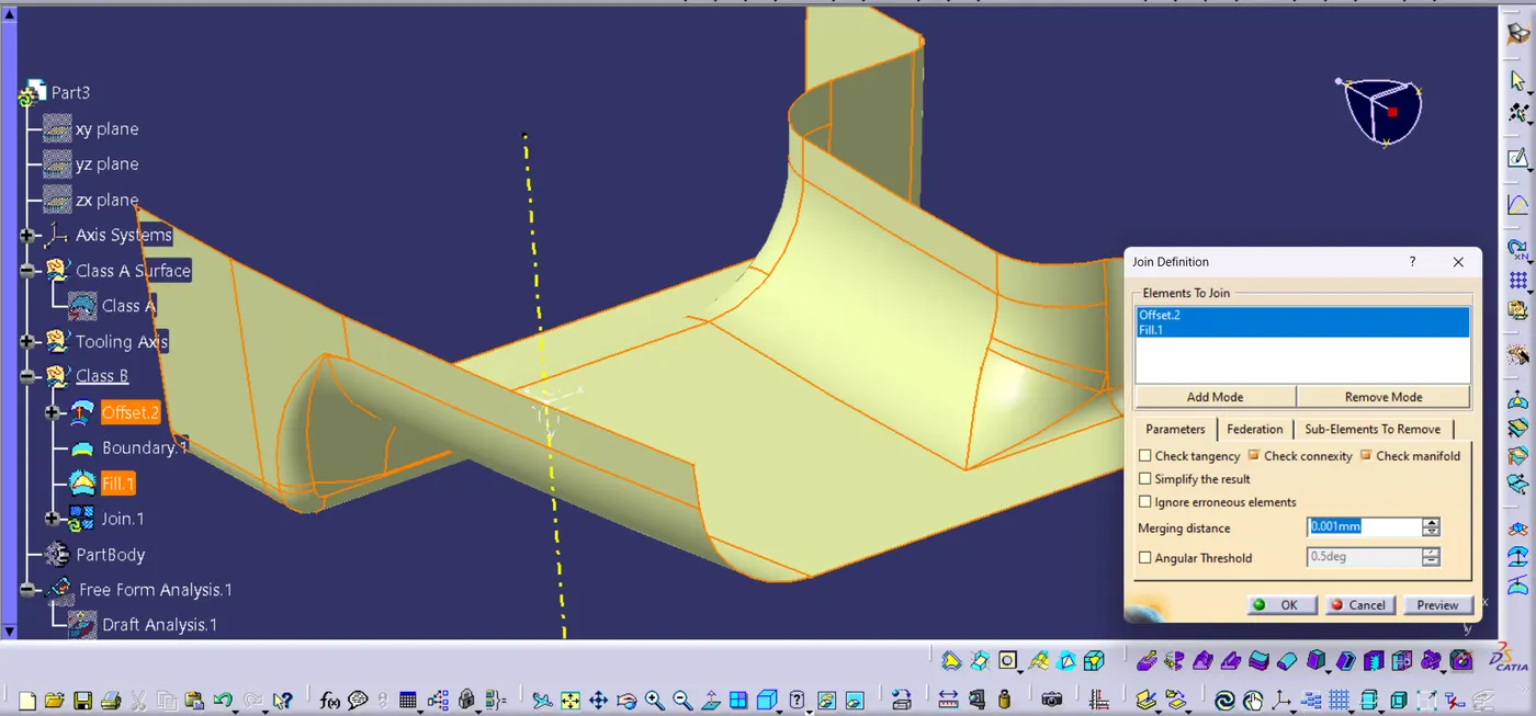
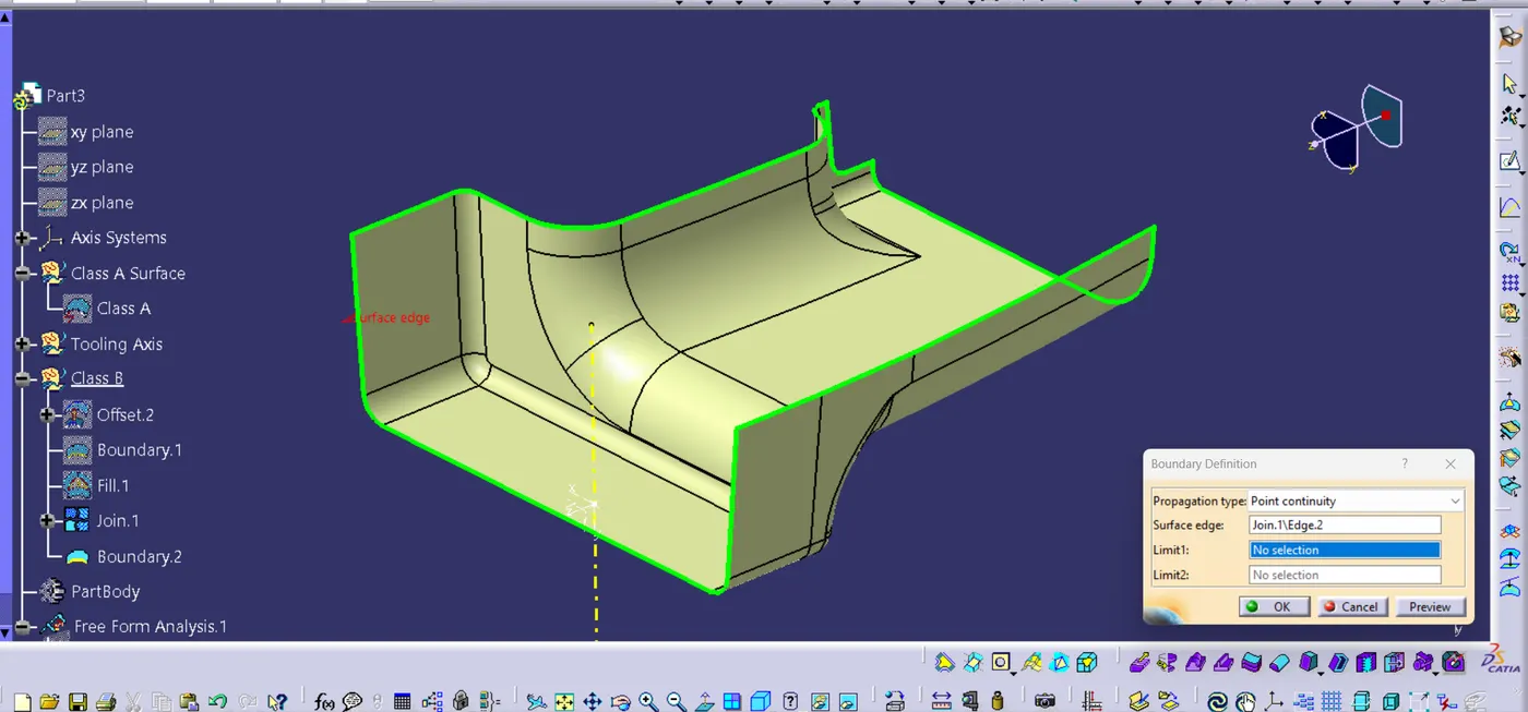
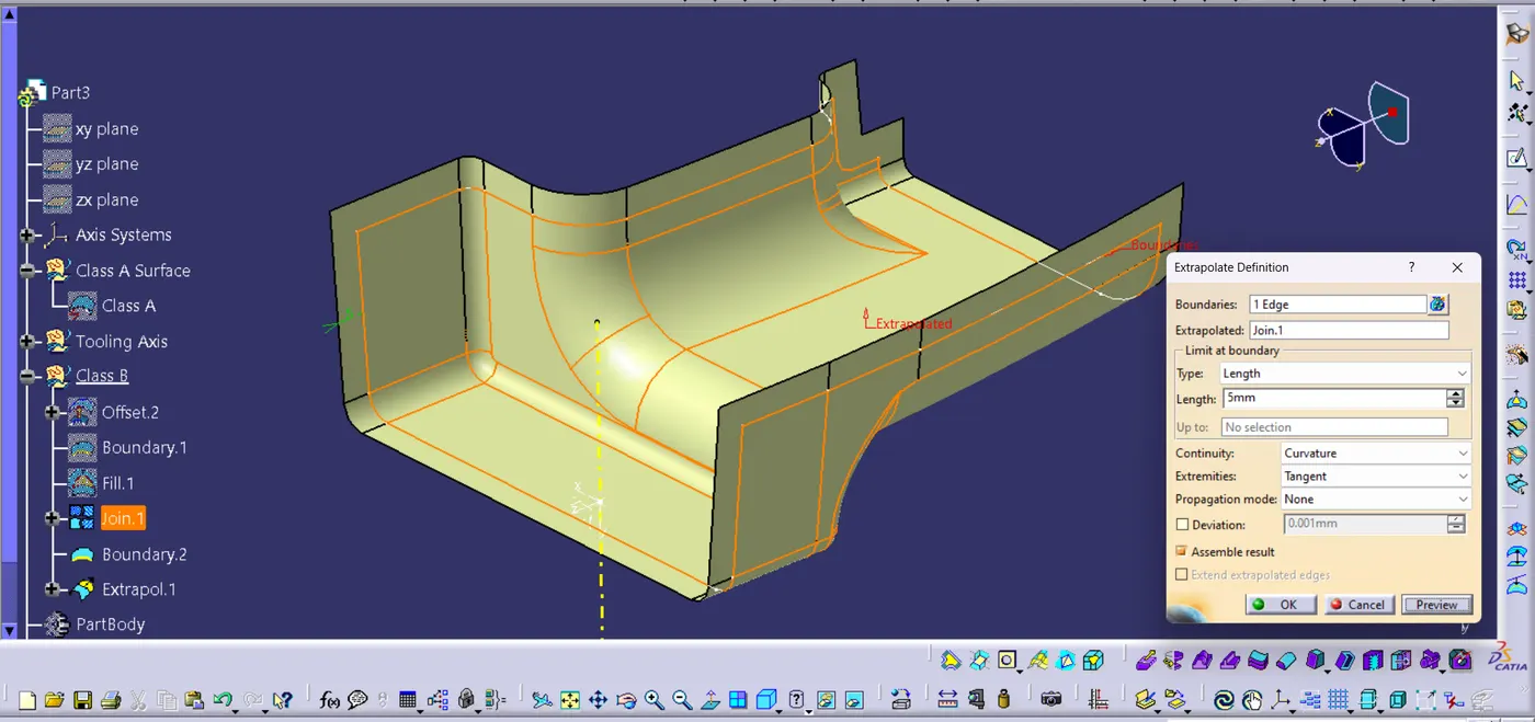
Step 5 : Creating Class C surface using 'Sweep' command also give the requied draft of 3 degree.
- Using 'Boundry' command create boundry
- Using 'Sweep' create the Class C surface with a draft of 3 degree.
- Then trim all the faces made by sweep to make it Class C surface.
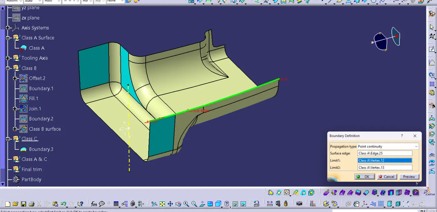

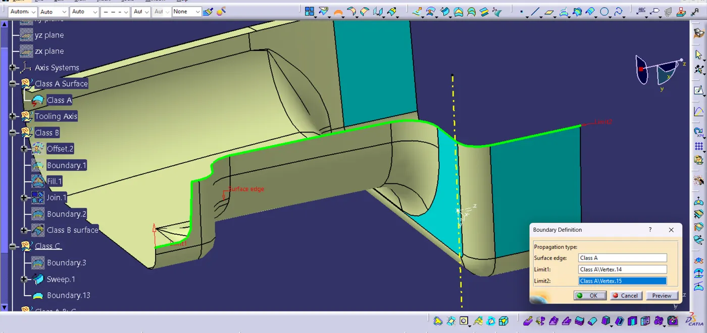
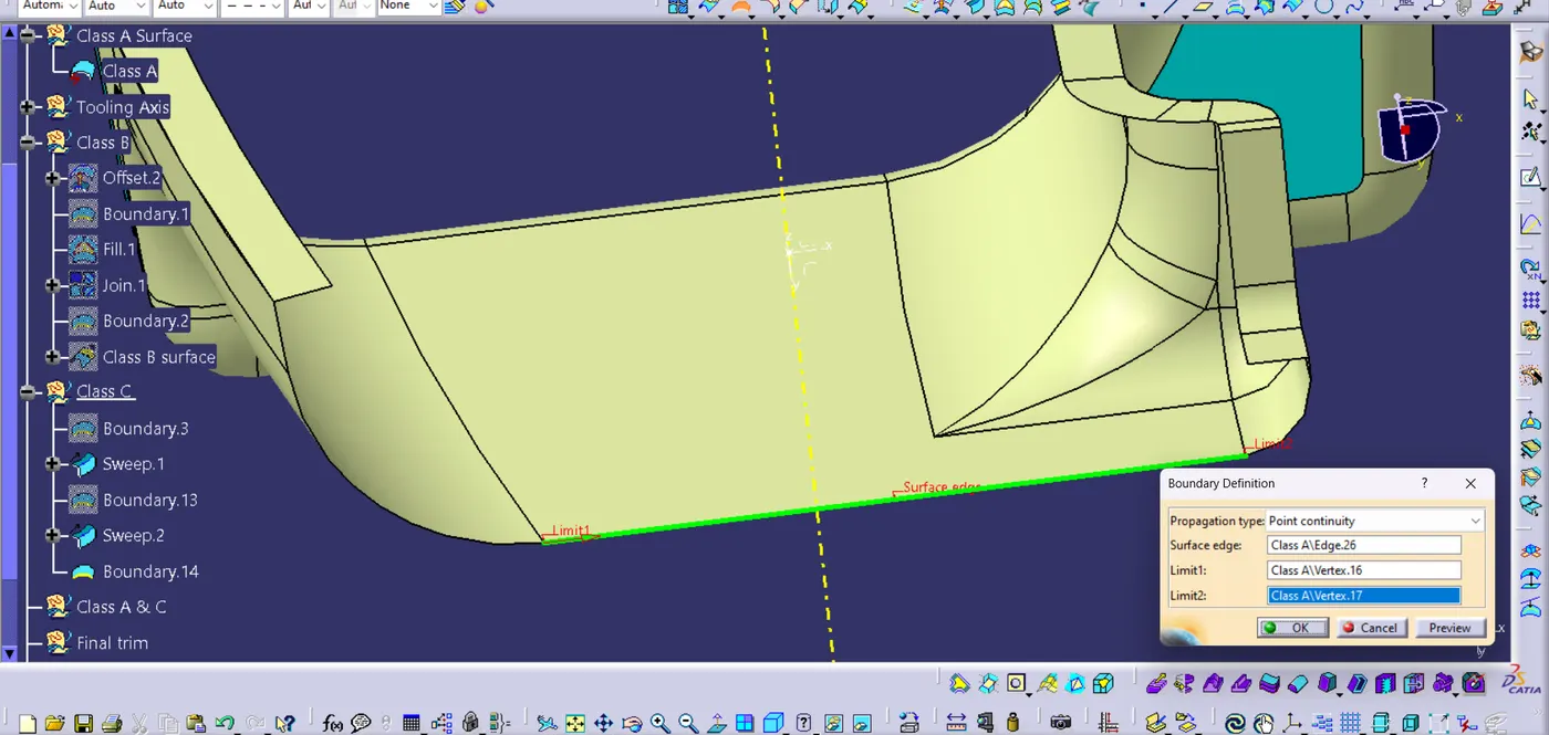
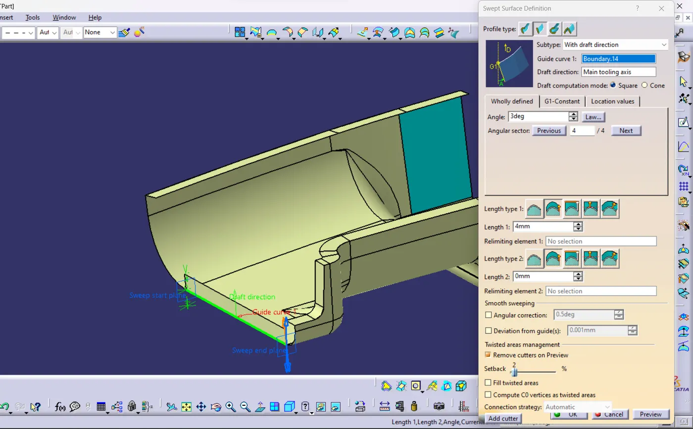
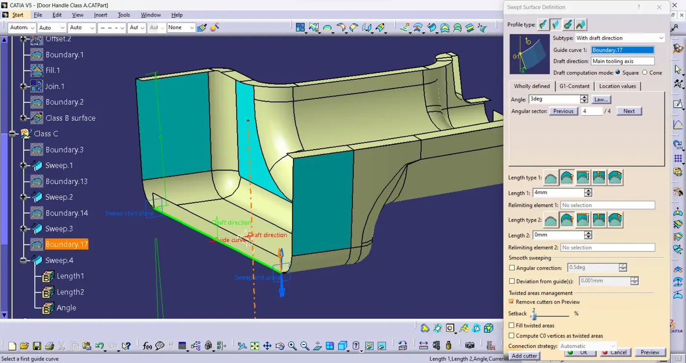
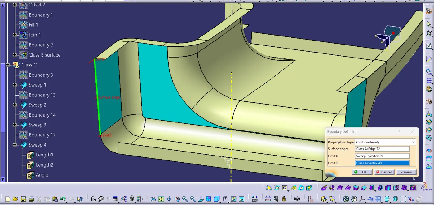
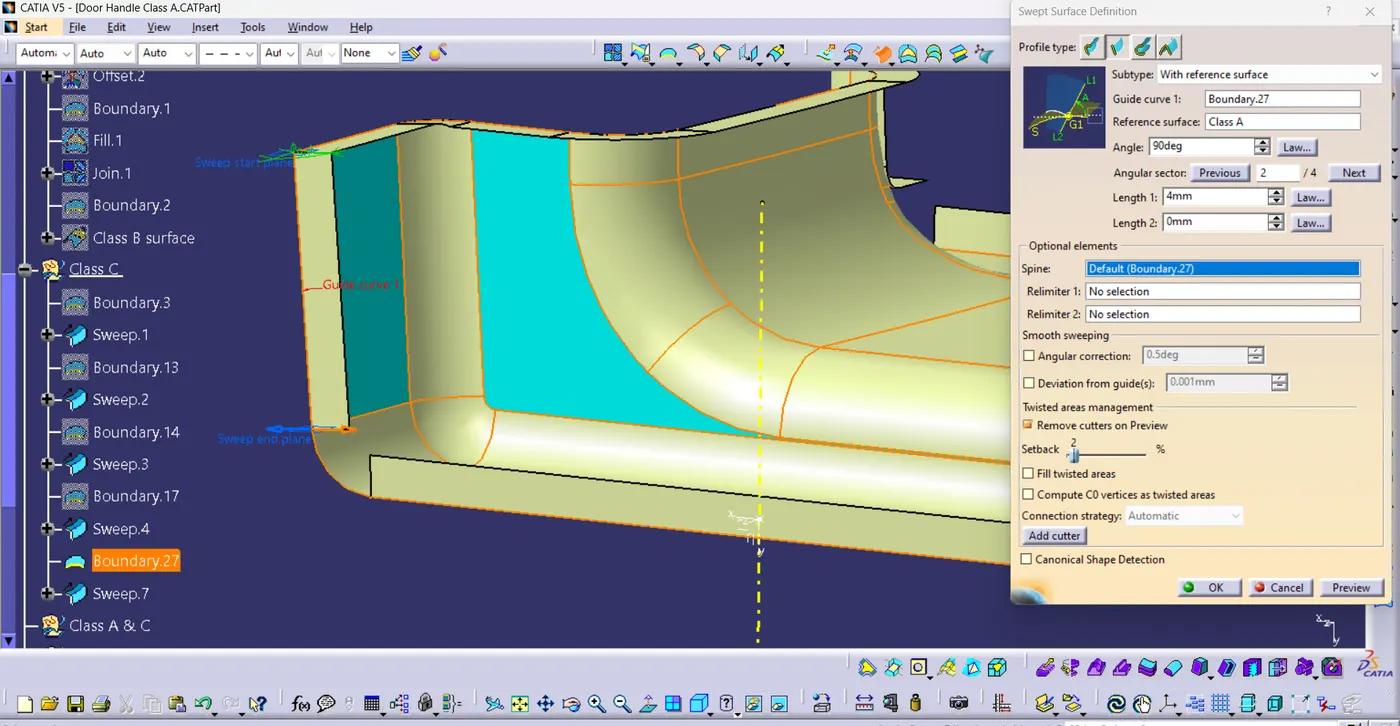
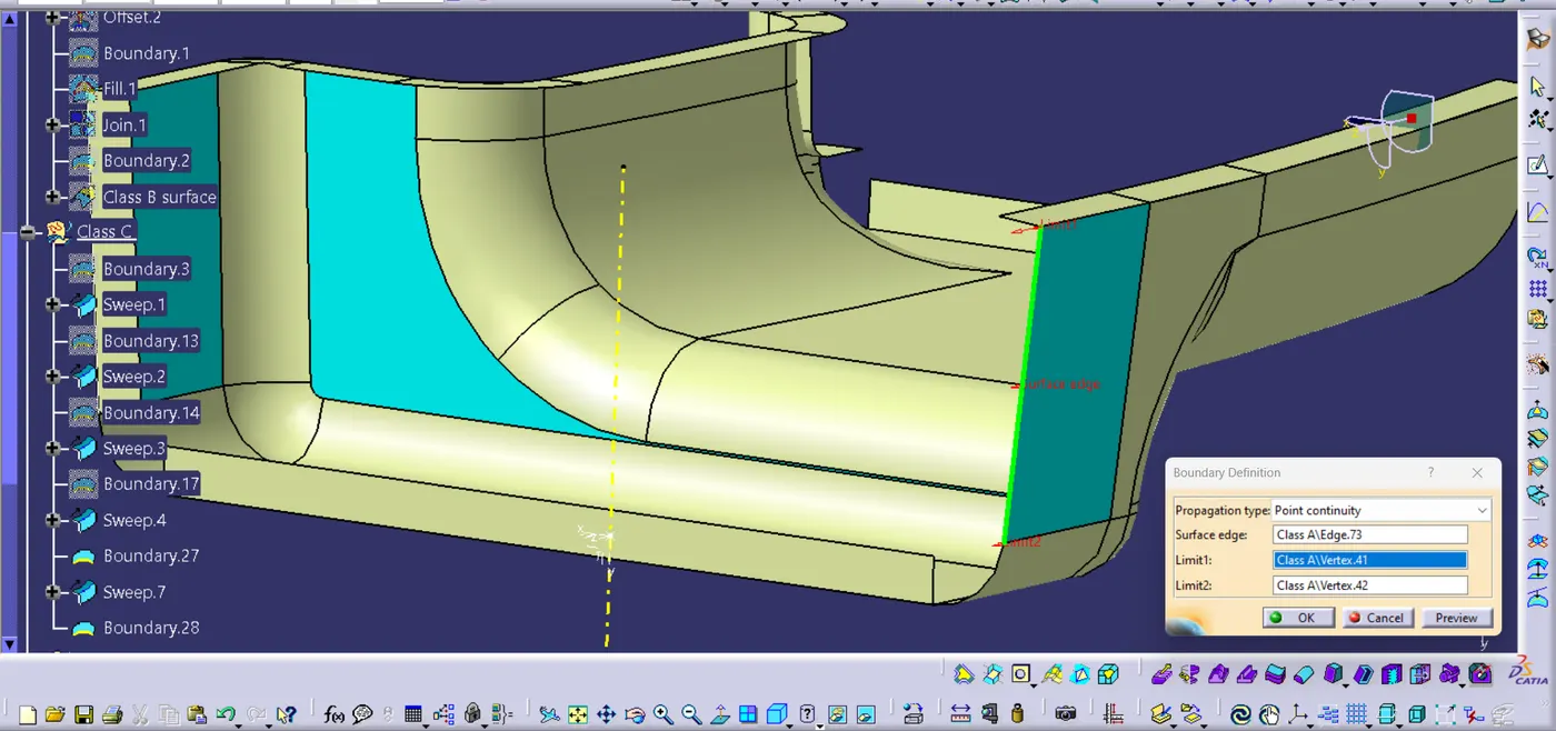

Inorder to make the edges of the class C surface 'sweep' command won't be enough so we use Multi Section Surface commnd to make the edges.
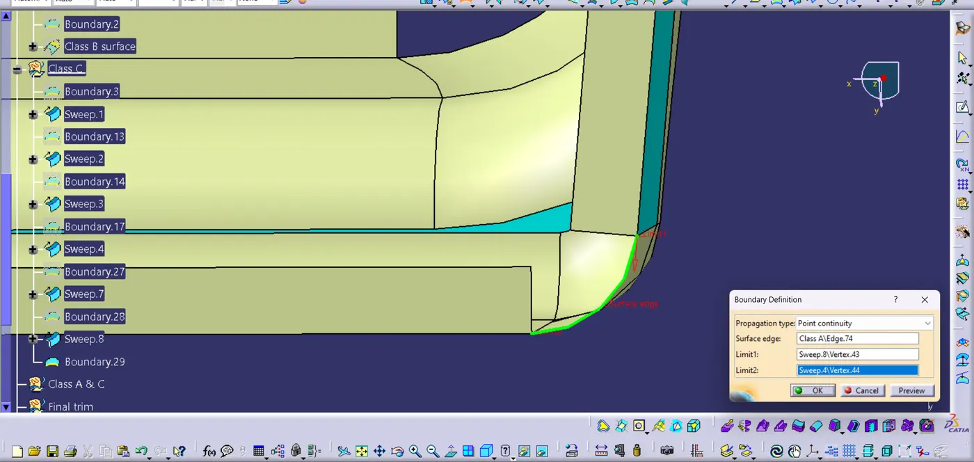
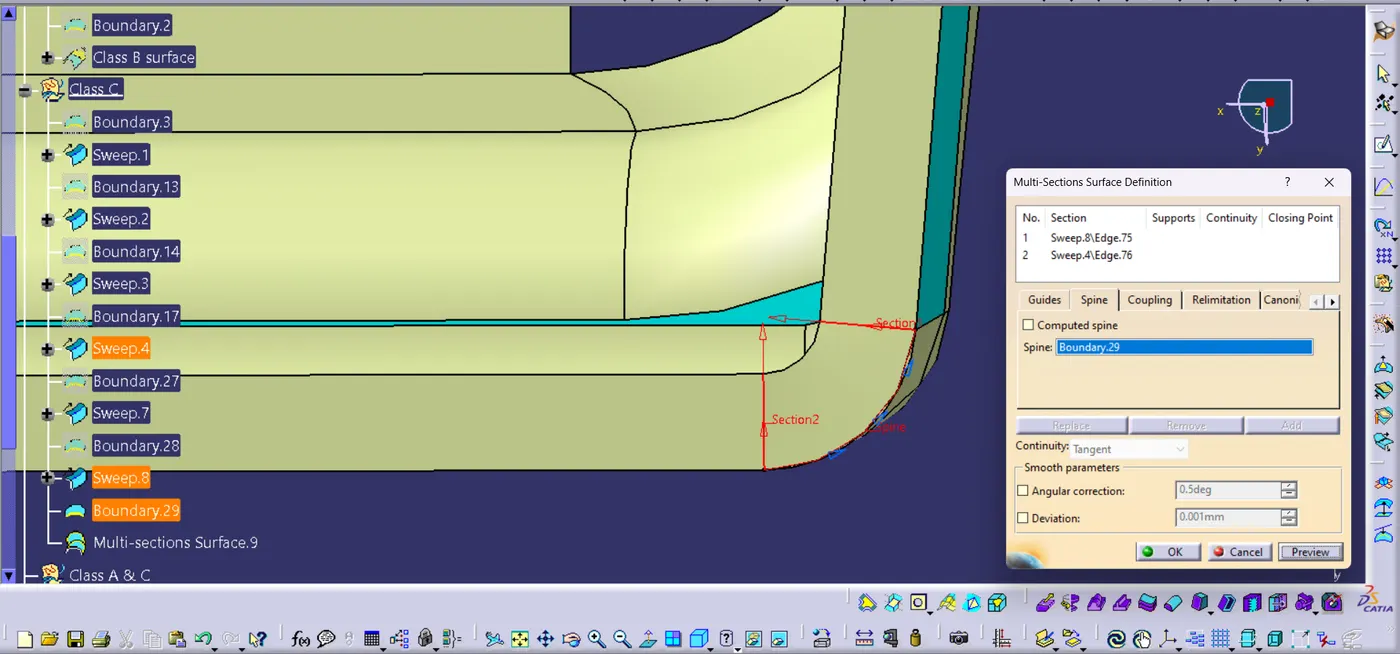
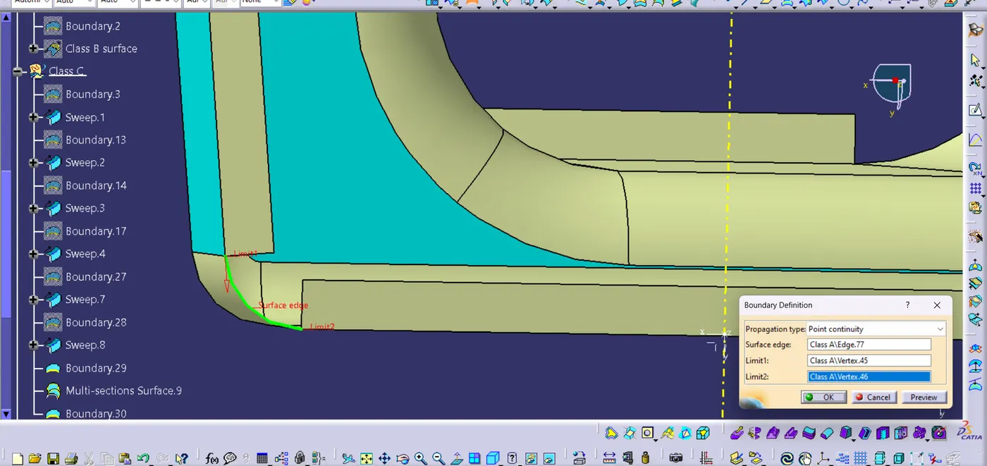
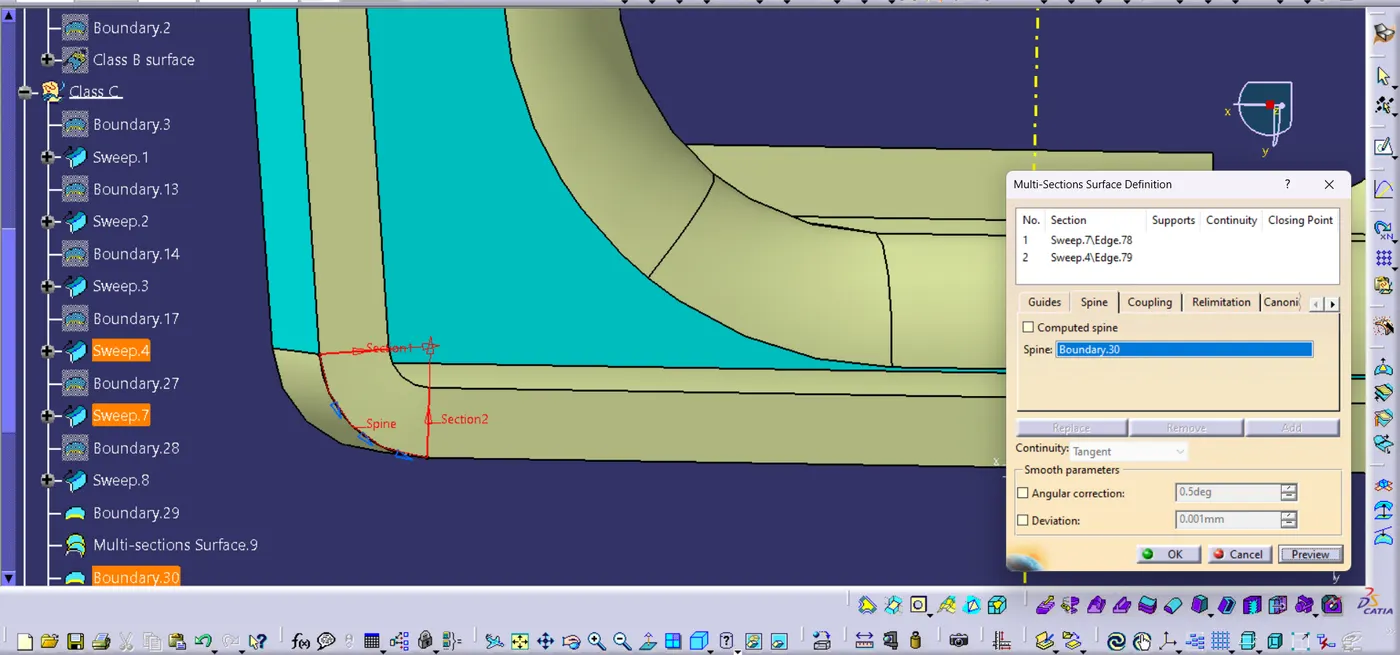
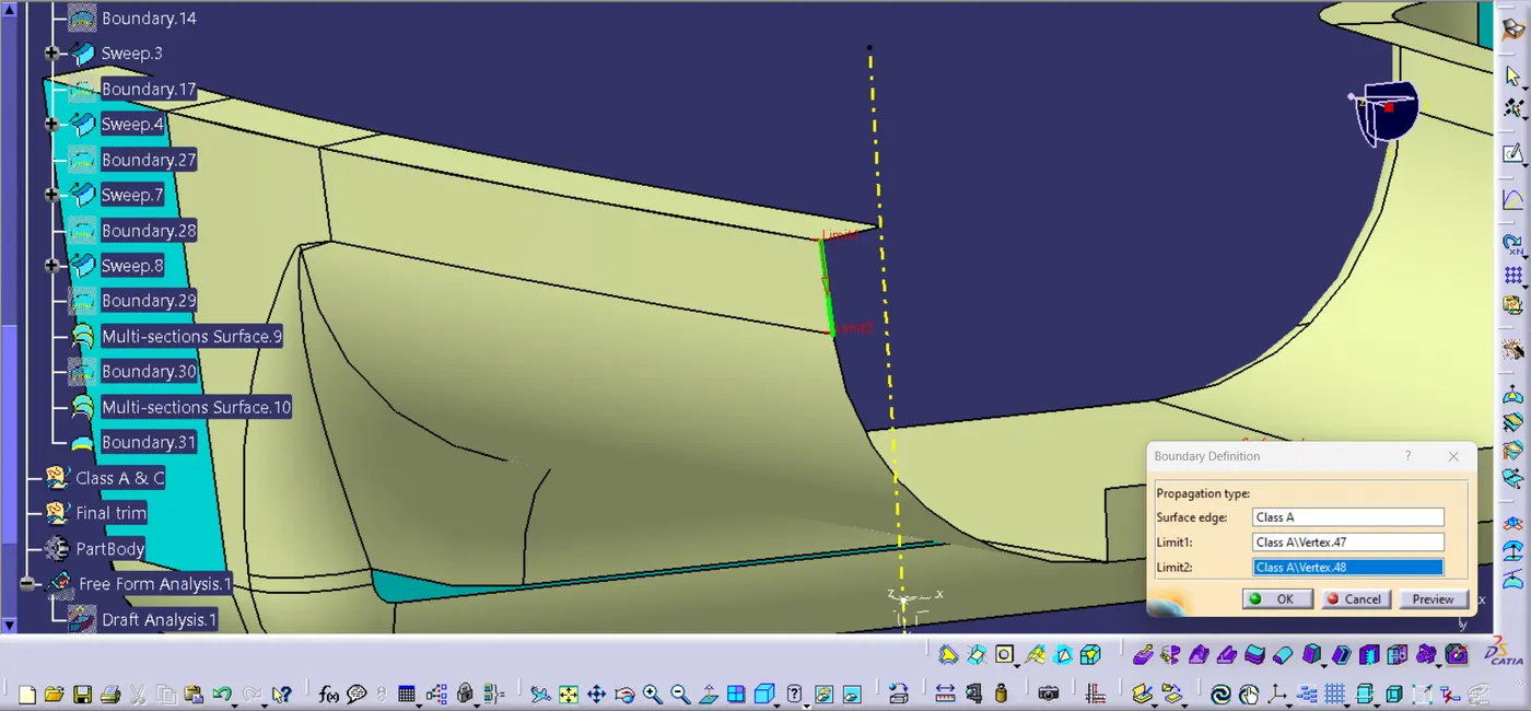
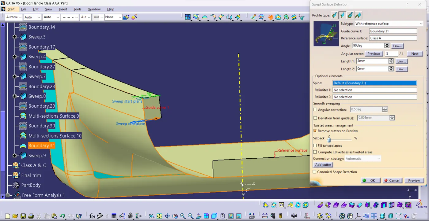
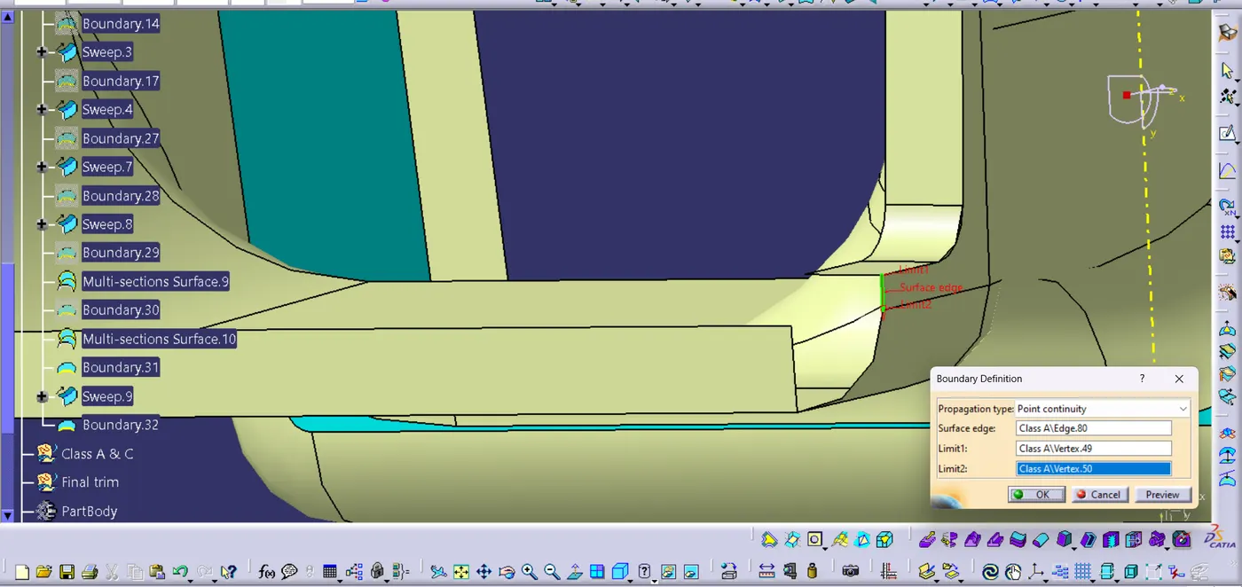
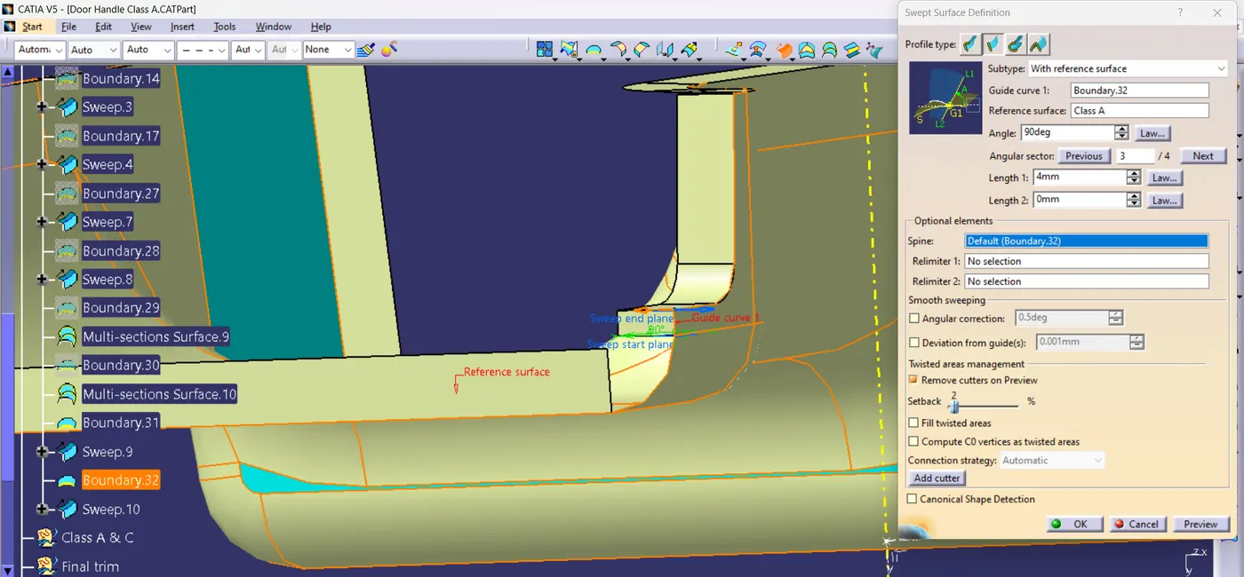
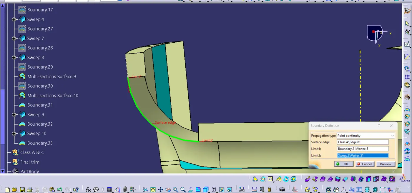
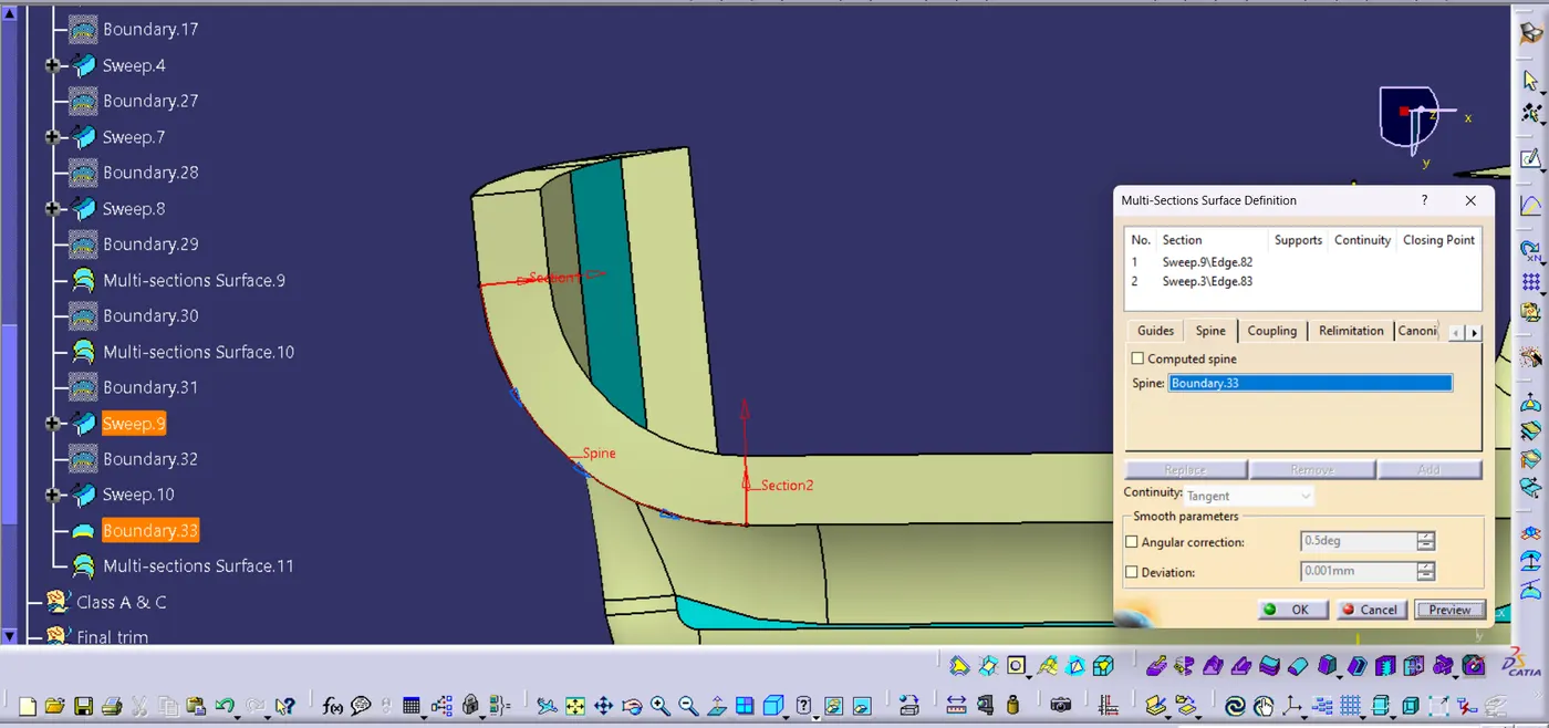
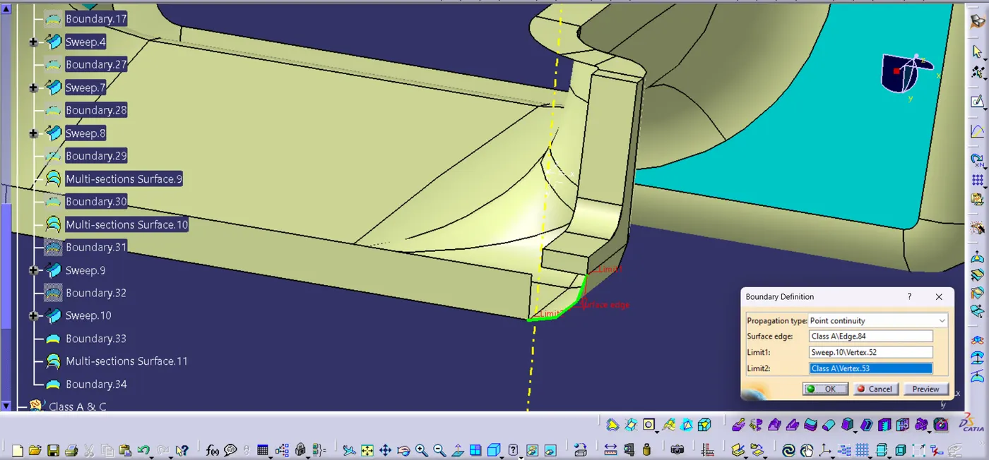
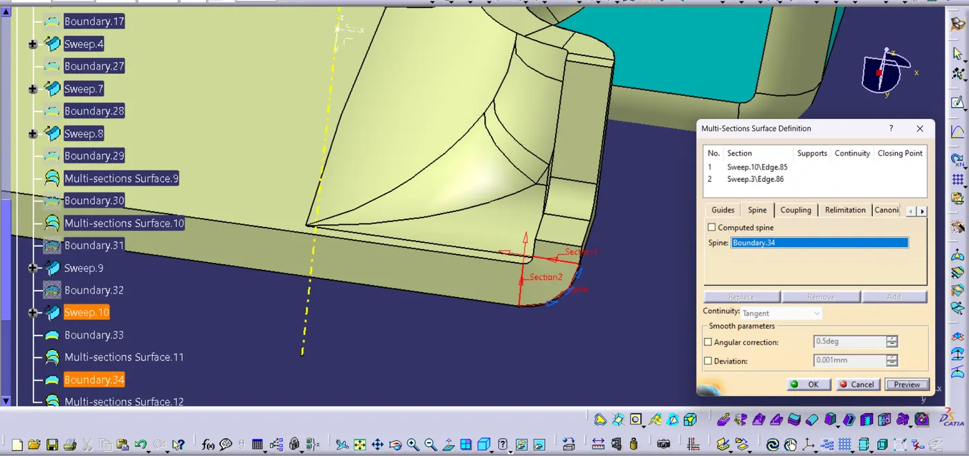
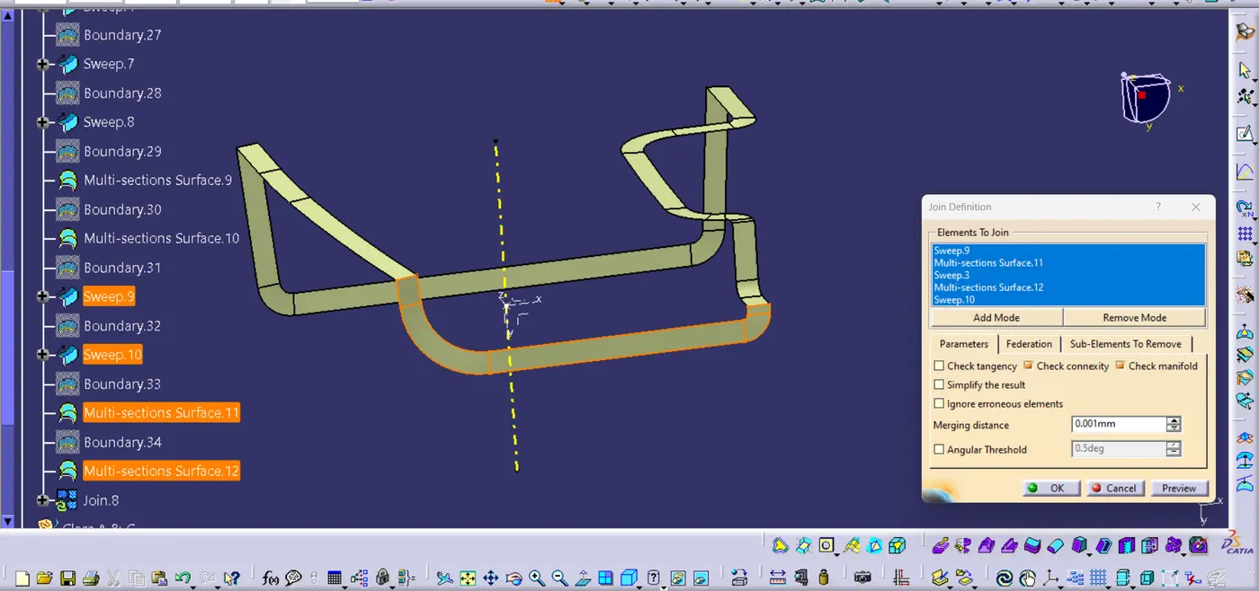
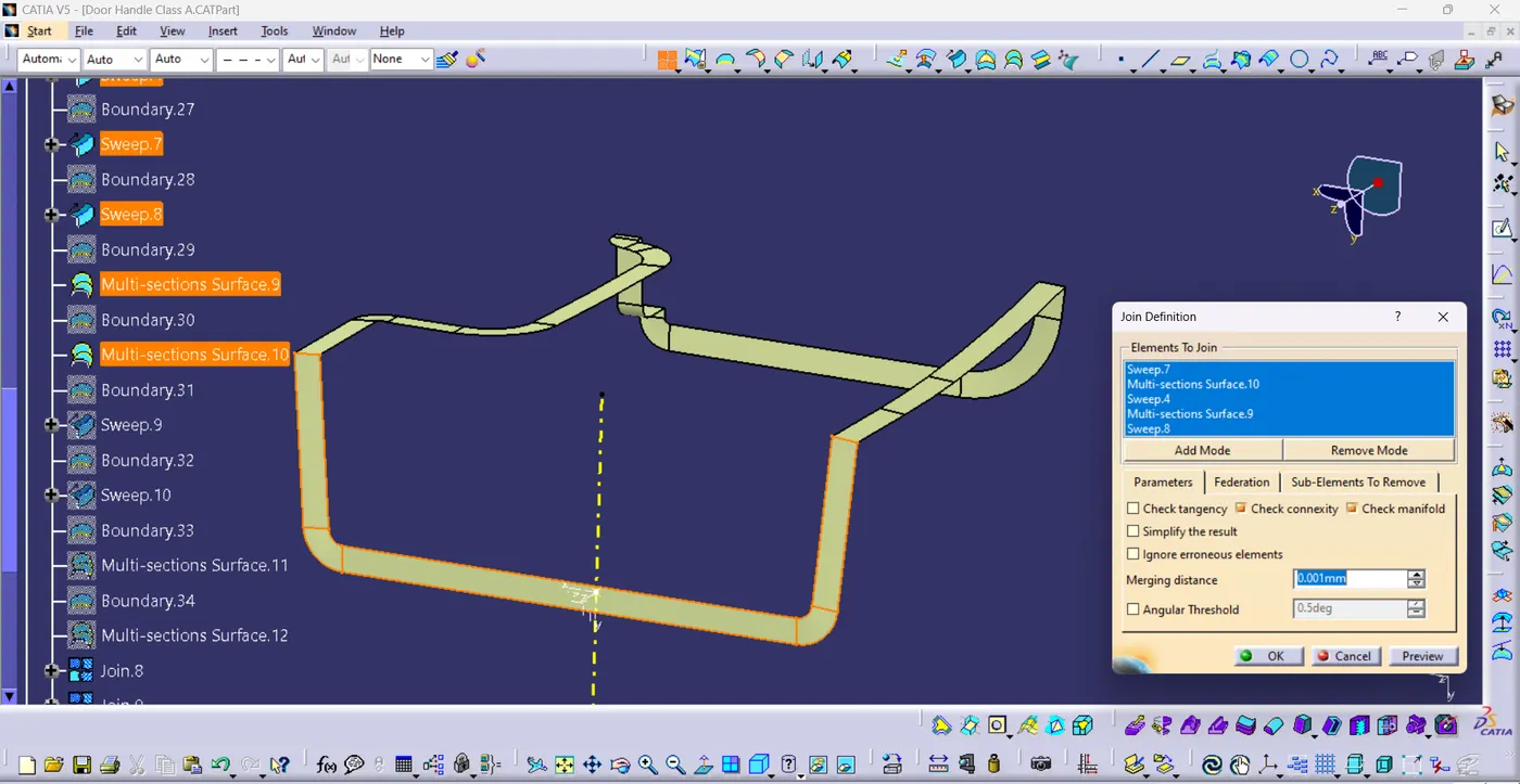
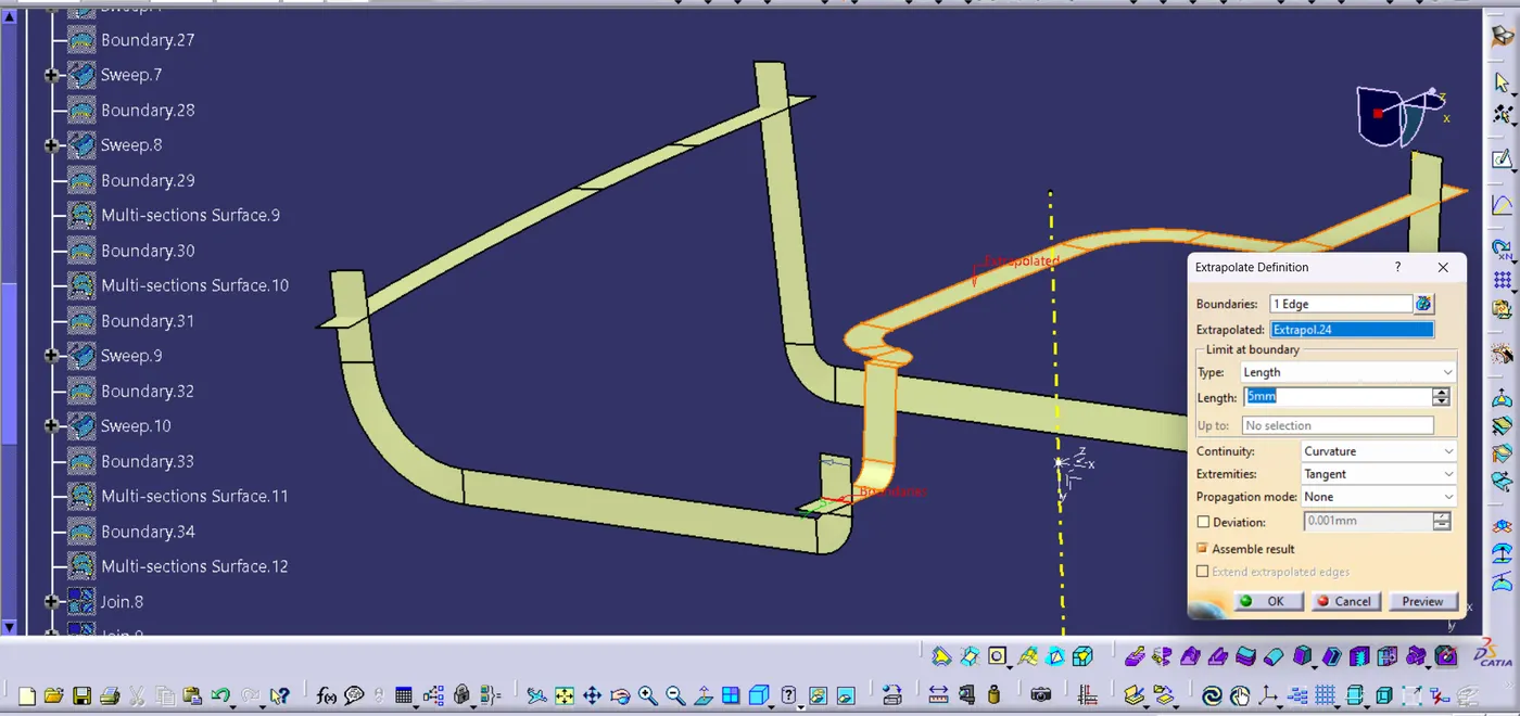
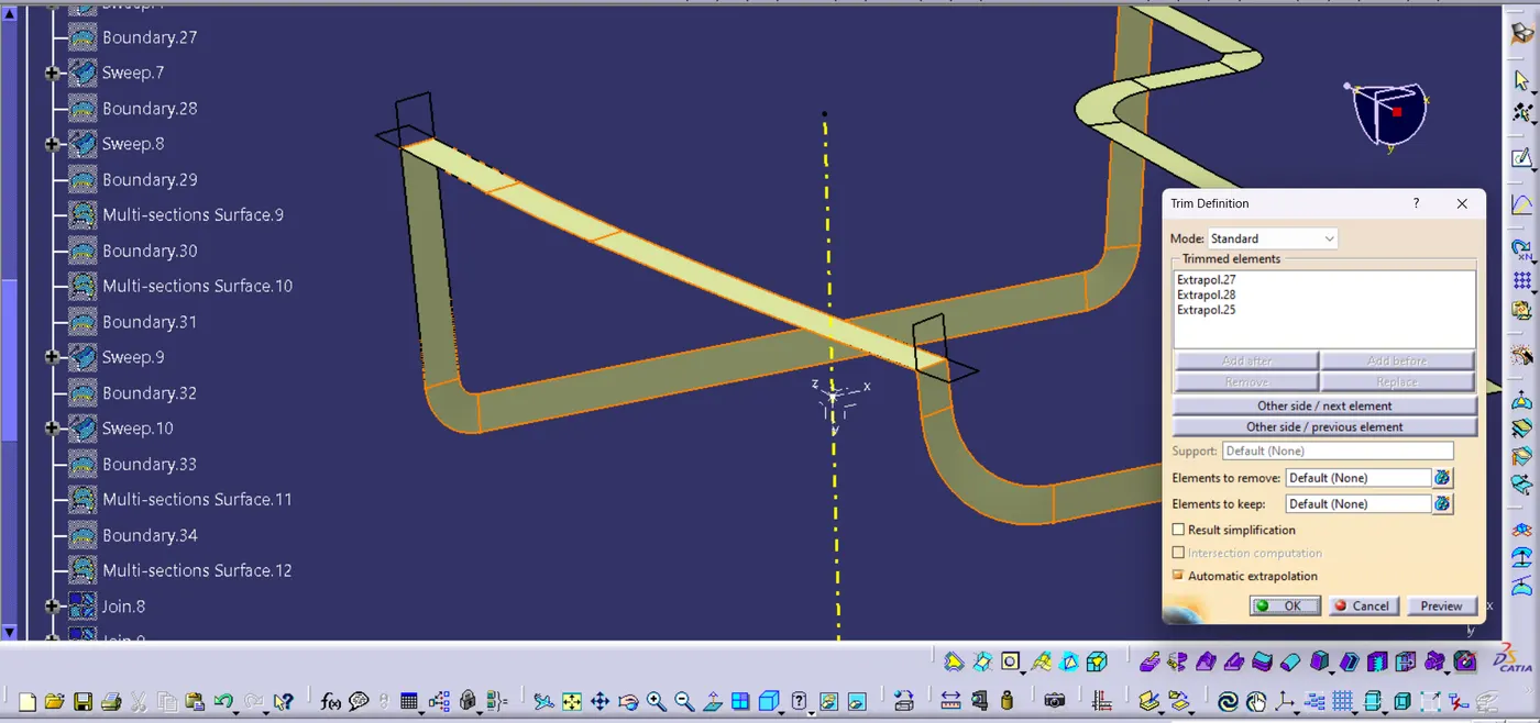
- After creating Class C Join it with Class A ,Check for any open boundry.
- Then trim the Class A&C with Class B surface to get the closed surface.
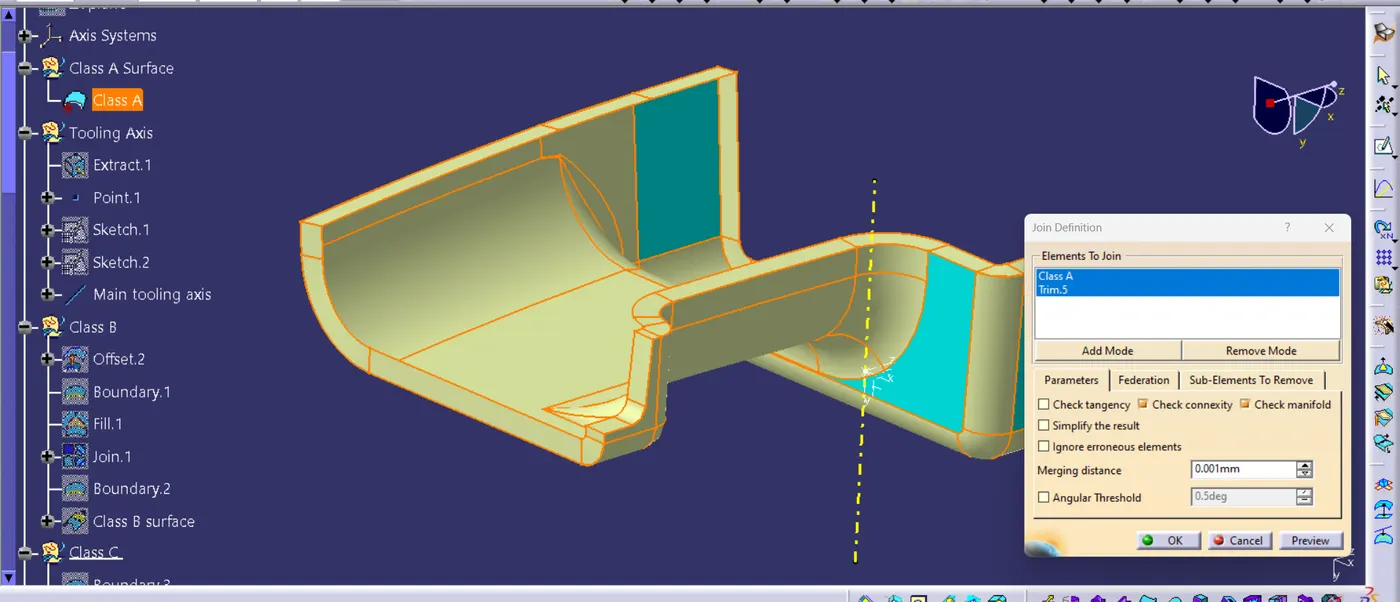
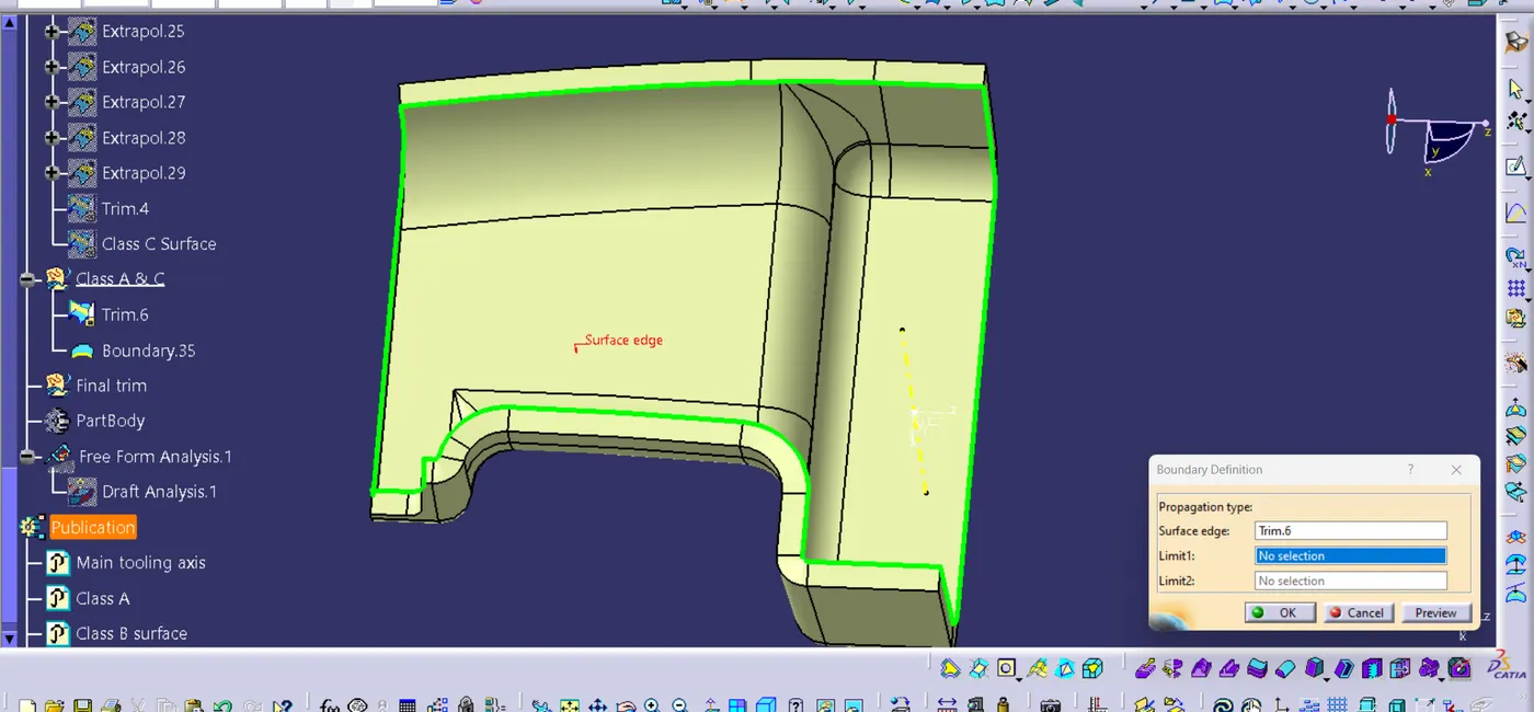
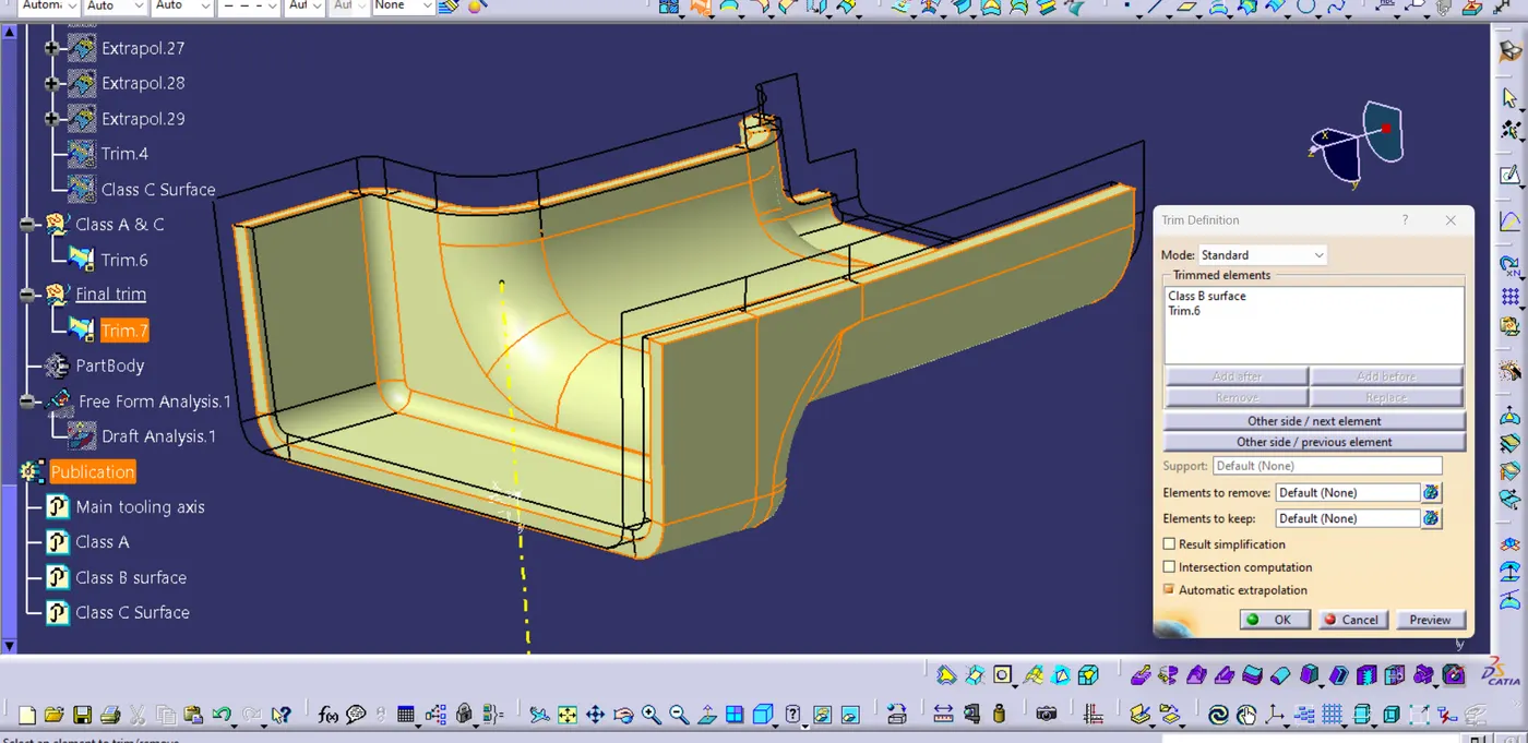
Step 6 : Convert closed surface into solid body
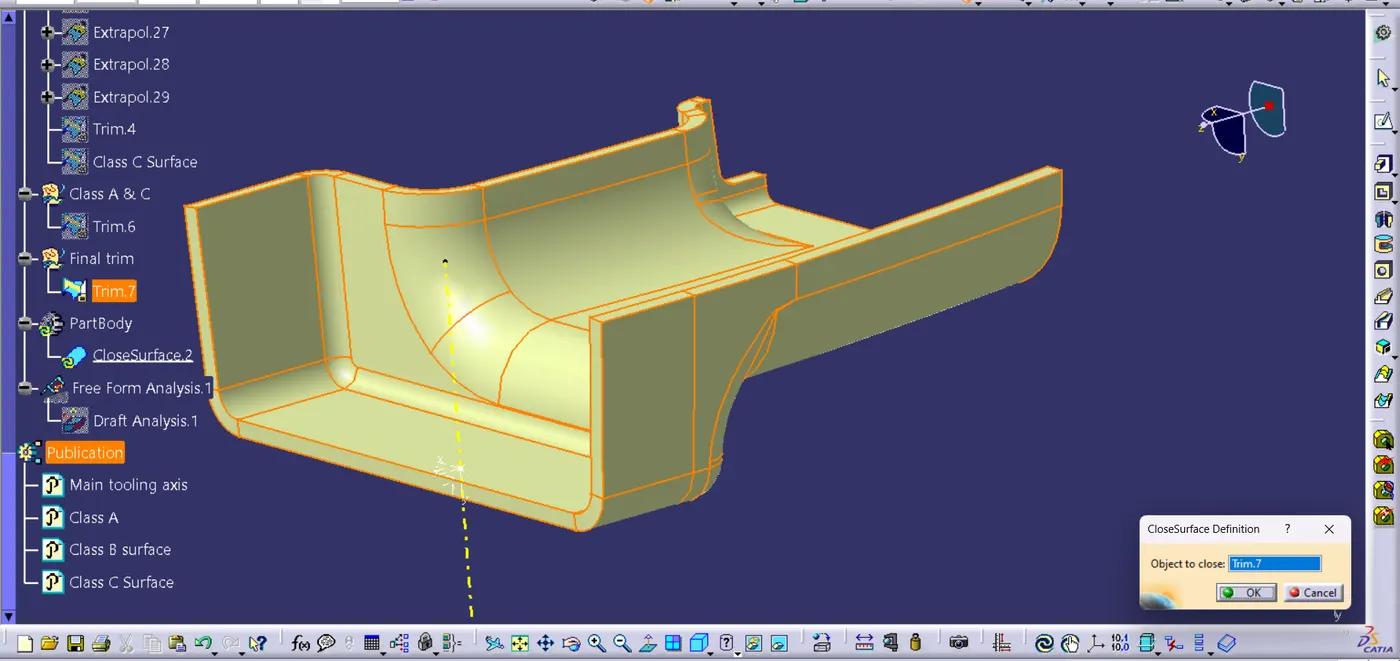
- After completing the closed surface switch to part design workbench and using Close surface command make it a solid body.
- After converting to solid body do the draft analys and make sure the body clears the draft of 3 degree.
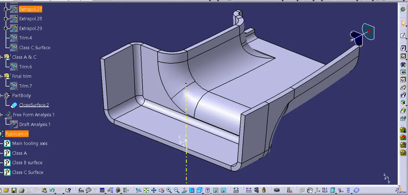
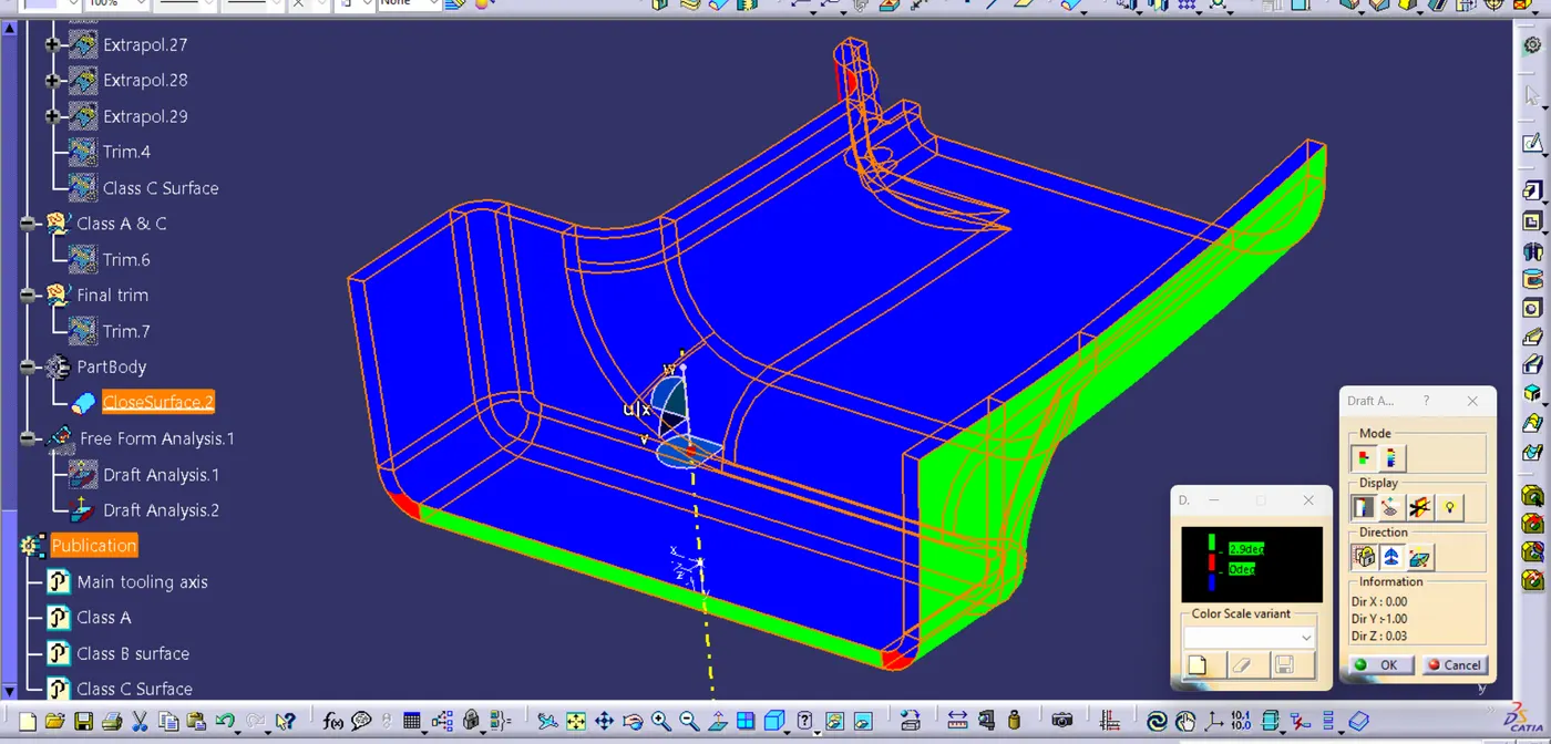
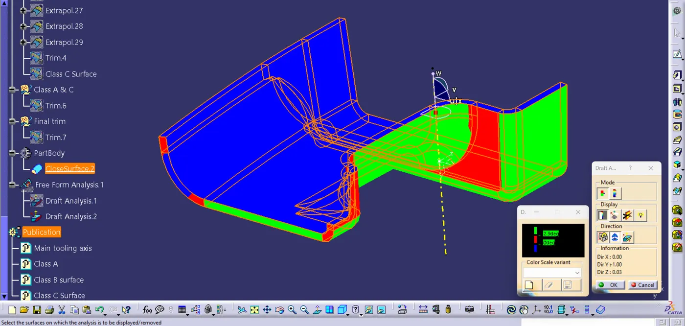
- Here in the draft analysis it is found that most of the class A surface is clearing the draft.
- But some of the areas are not clearing, so the surface need to send back for class A modification so that the class A surface clear the draft.
Step 7 : Designing the Rib with the guidlines.
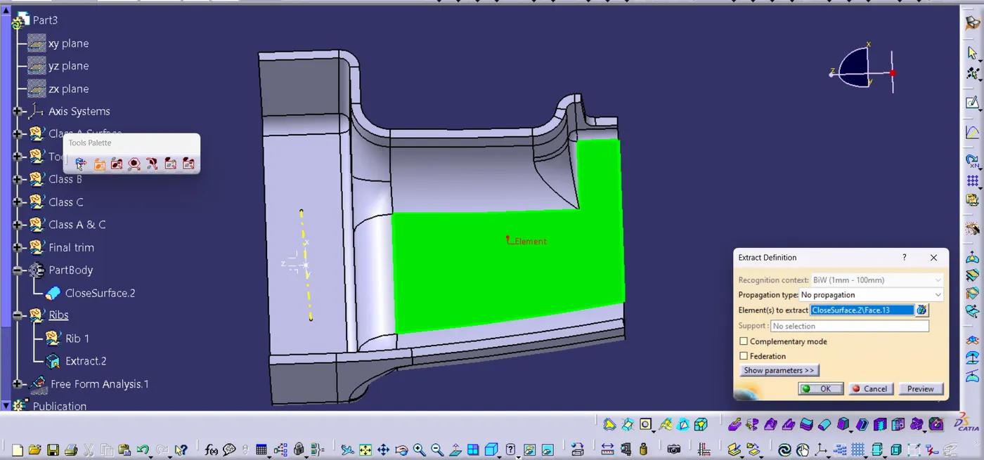
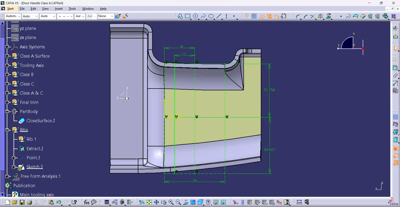
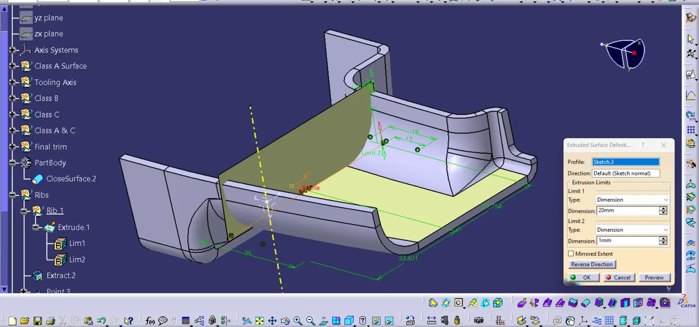
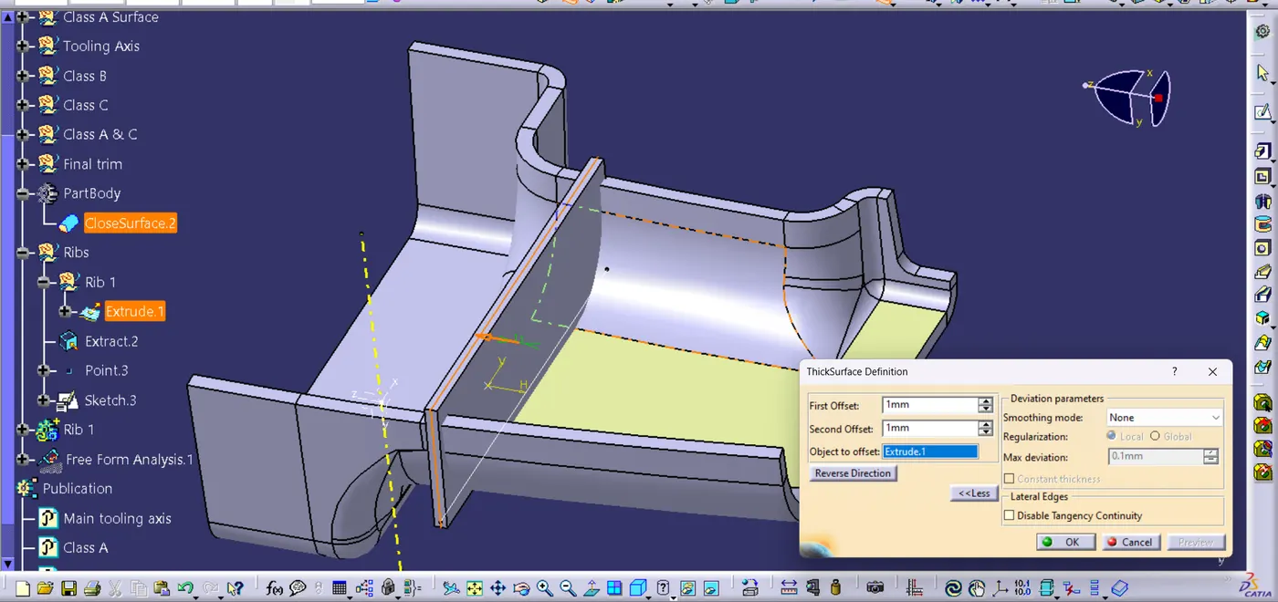
- Thickness (Max) of the Rib = 0.4 * Thickness of the surface
= 0.4 * 2.5
= 1 mm
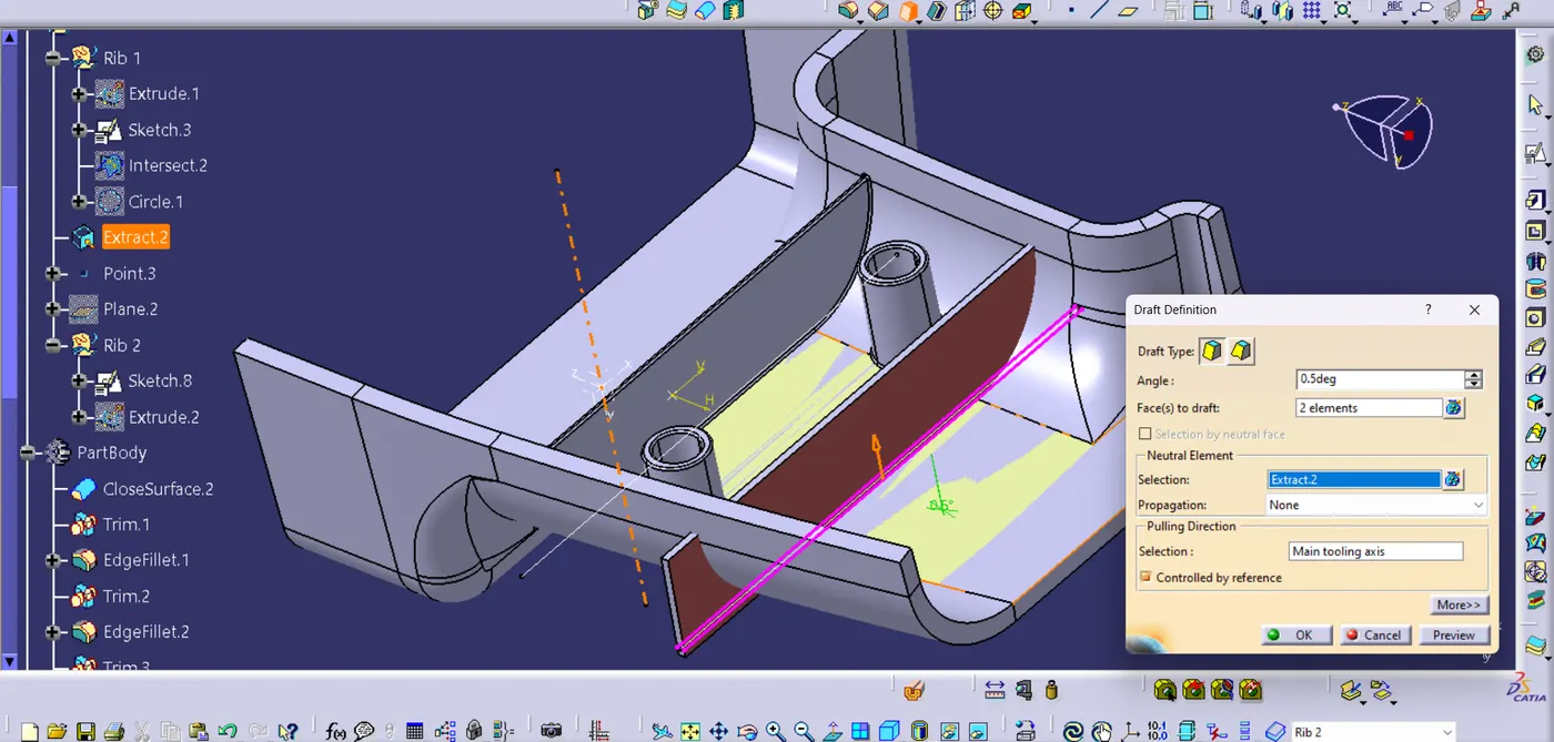
- The draft of Rib should be 0.5 degree
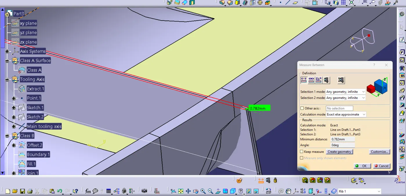
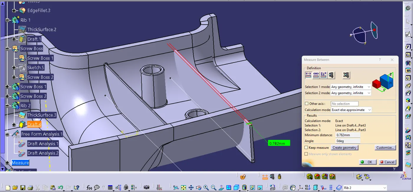
- The Top Thickness of Rib should be >0.75 mm

The Rib Top Thickness is = 0.78 mm
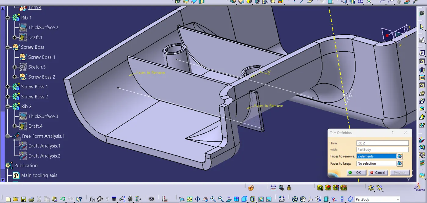
- Using Union trim command Trim and add the Rib to main body
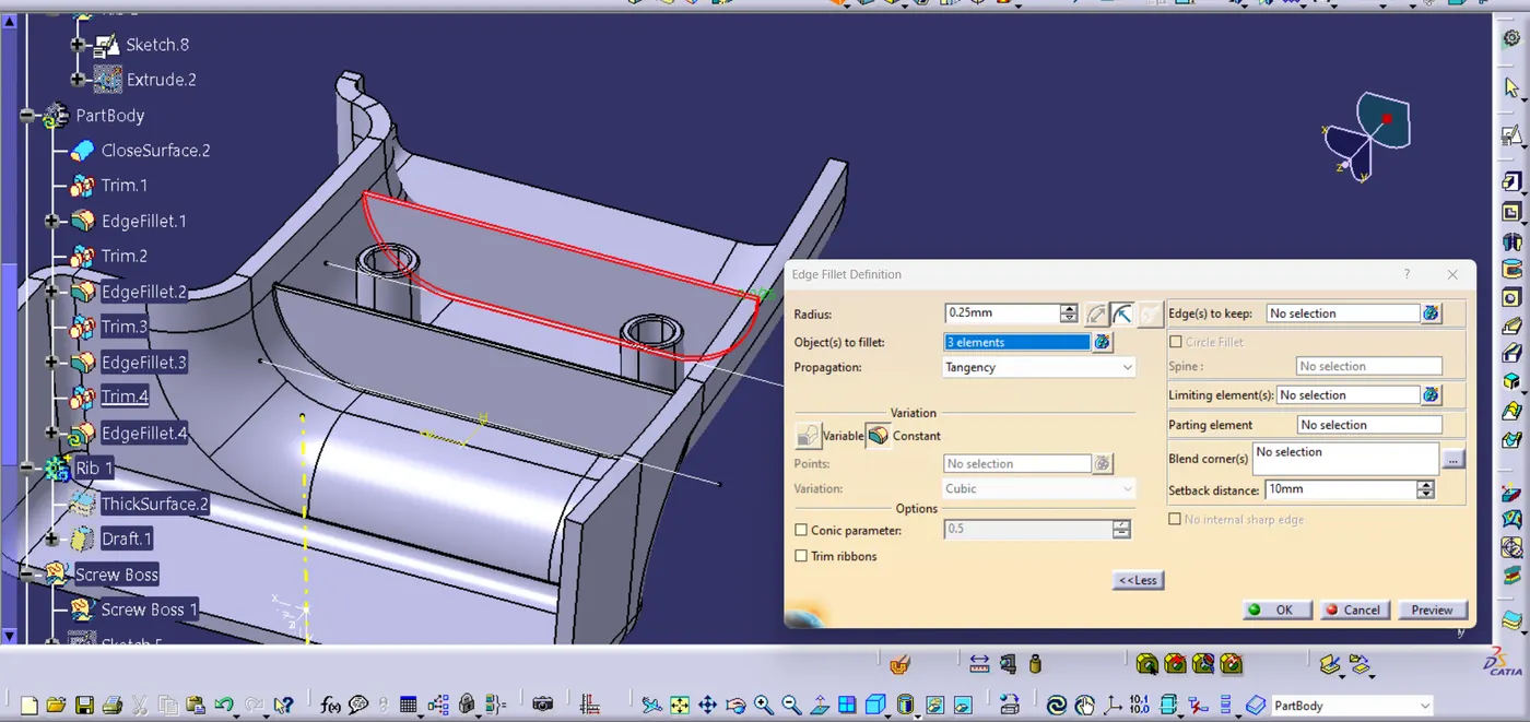
- Then give fillet which should be maximum of 0.25 mm
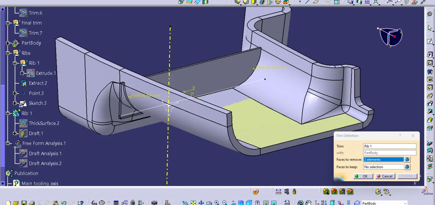
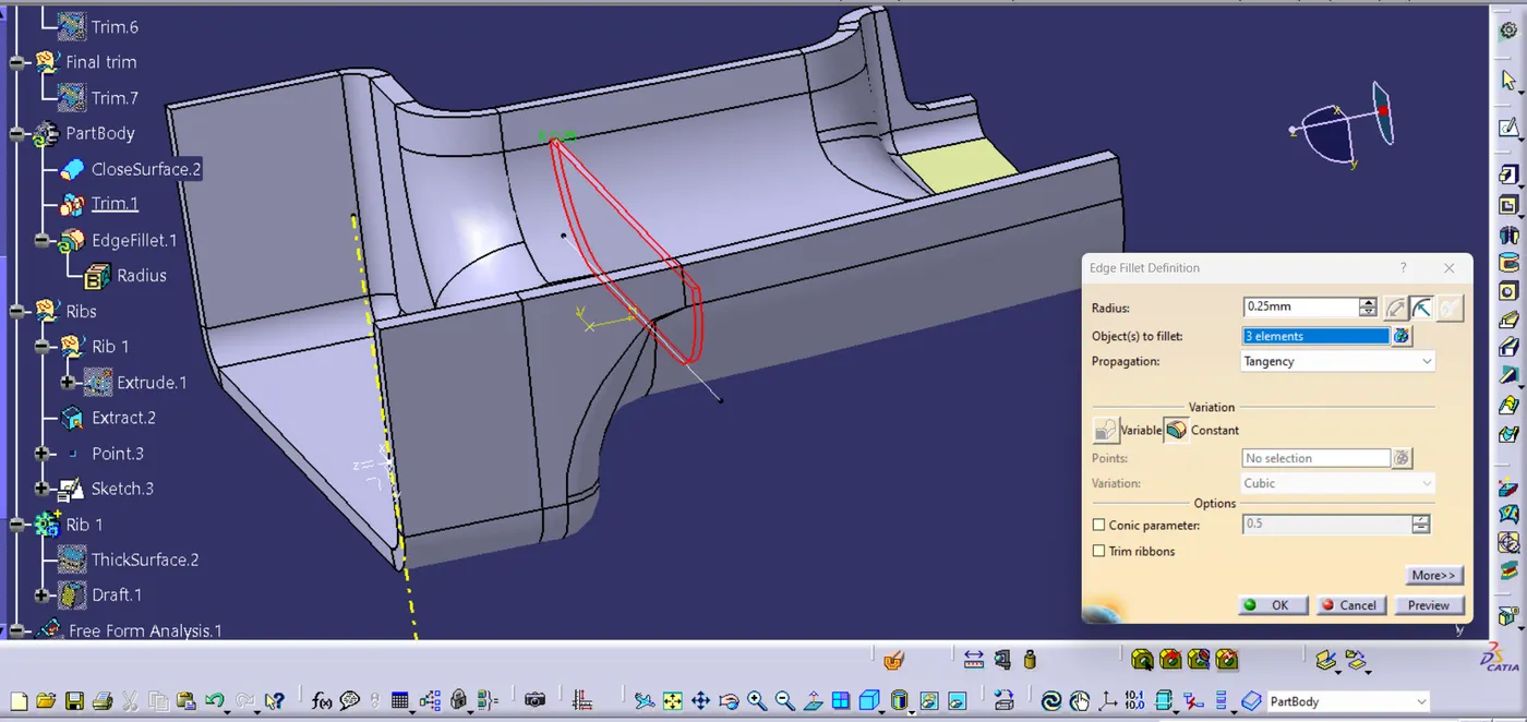
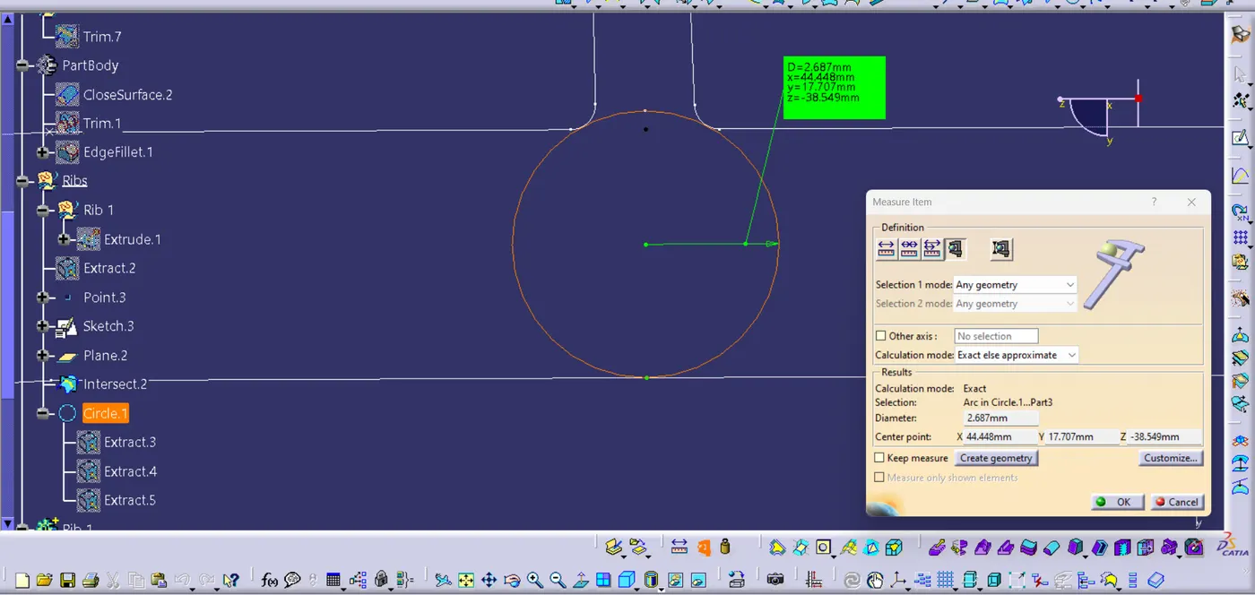
Check for Rib Root Thickness, The Rib Root Thickness should be - +- 30% of wall thickness
= 2.5 +- 30% * 2.5 mm
= 1.75 mm to 3.25 mm
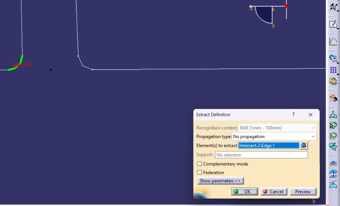
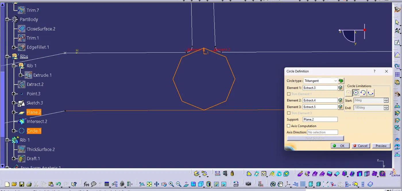
Intersect the body -> Draw circle using Tirtangent circle with the filleted edges(Create extract)-> Measure the Diameter
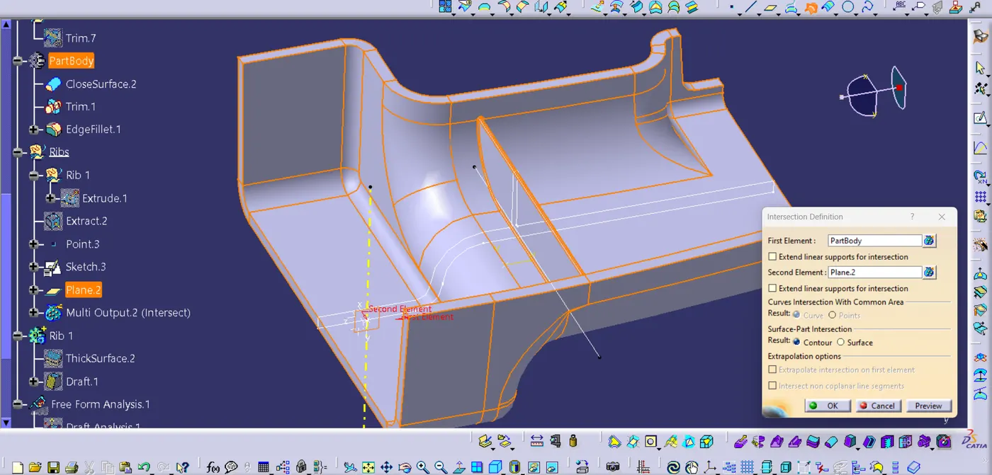
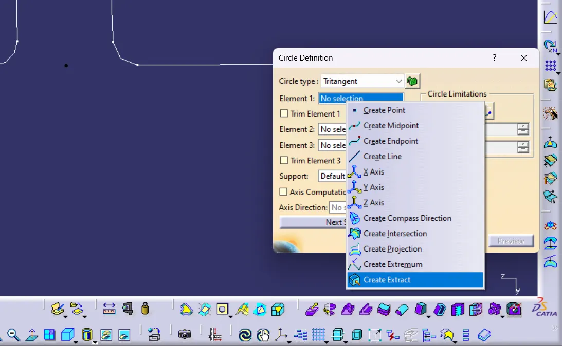
Step 8 : Next the Screw Bosses are to be designed
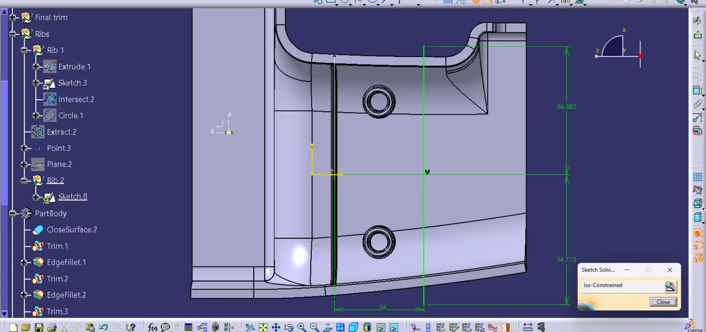
The distance between ribs and boss should be minimum of 3 times Wall Thickness = 3* 2.5
= 7.5 mm
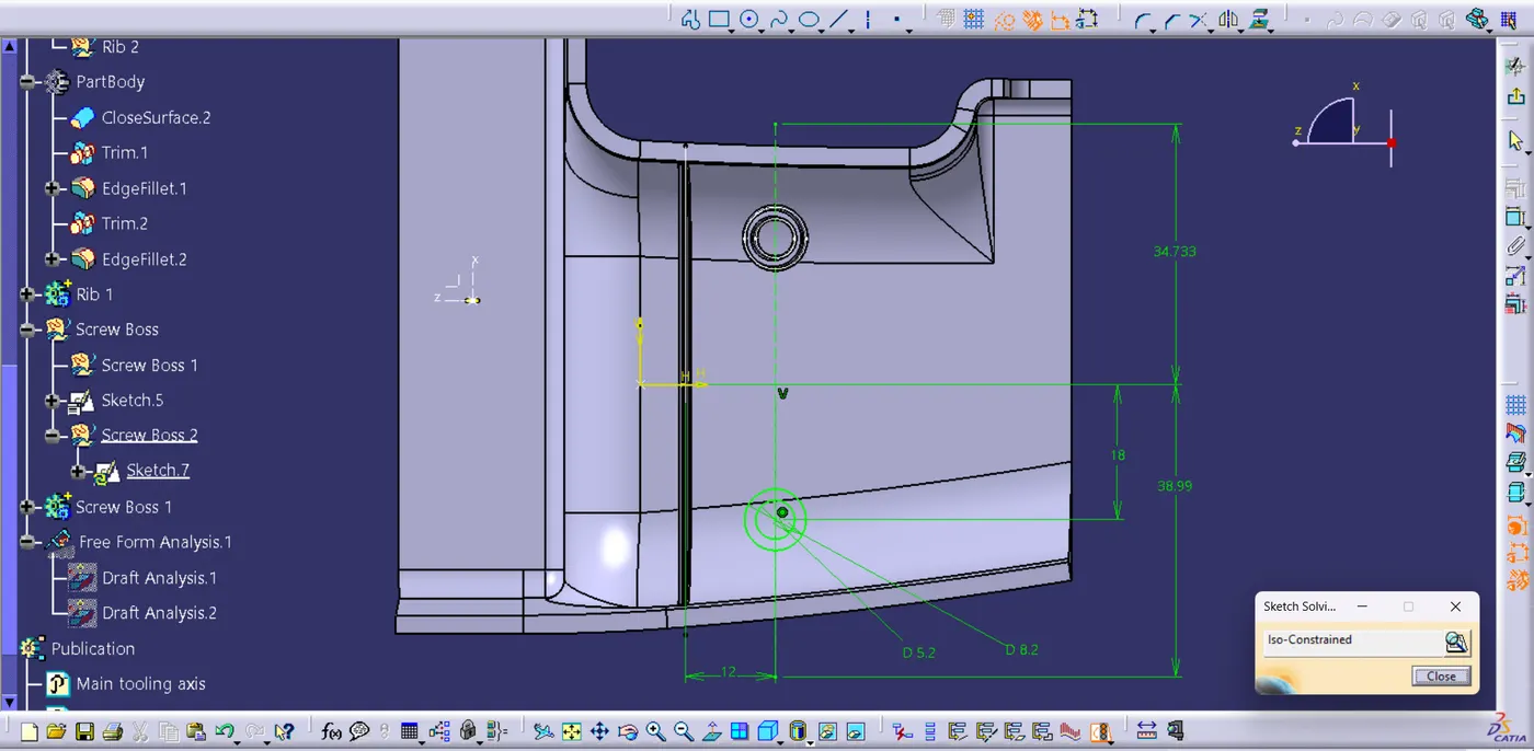
Here a Screw boss for M6 screw is made
So the inner hole diameter will be = 5.2 mm
We know the boss wall thickness should be W= 0.6 * Thickness of surface
= 0.6 * 2.5
= 1.5
So the outer Circle diameter of Screw boss = 5.2+1.5+1.5
= 8.2 mm
So the Distance from Rib 1 to Screw Boss = (8.2/2) + (3*2.5)
= 11.6, lets take it as 12 mm
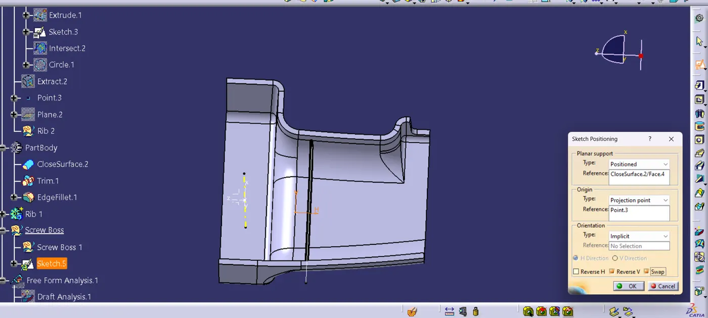
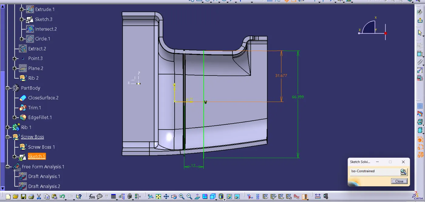
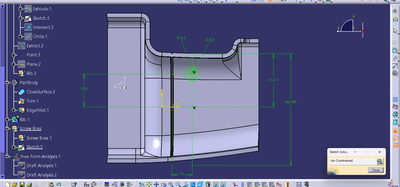
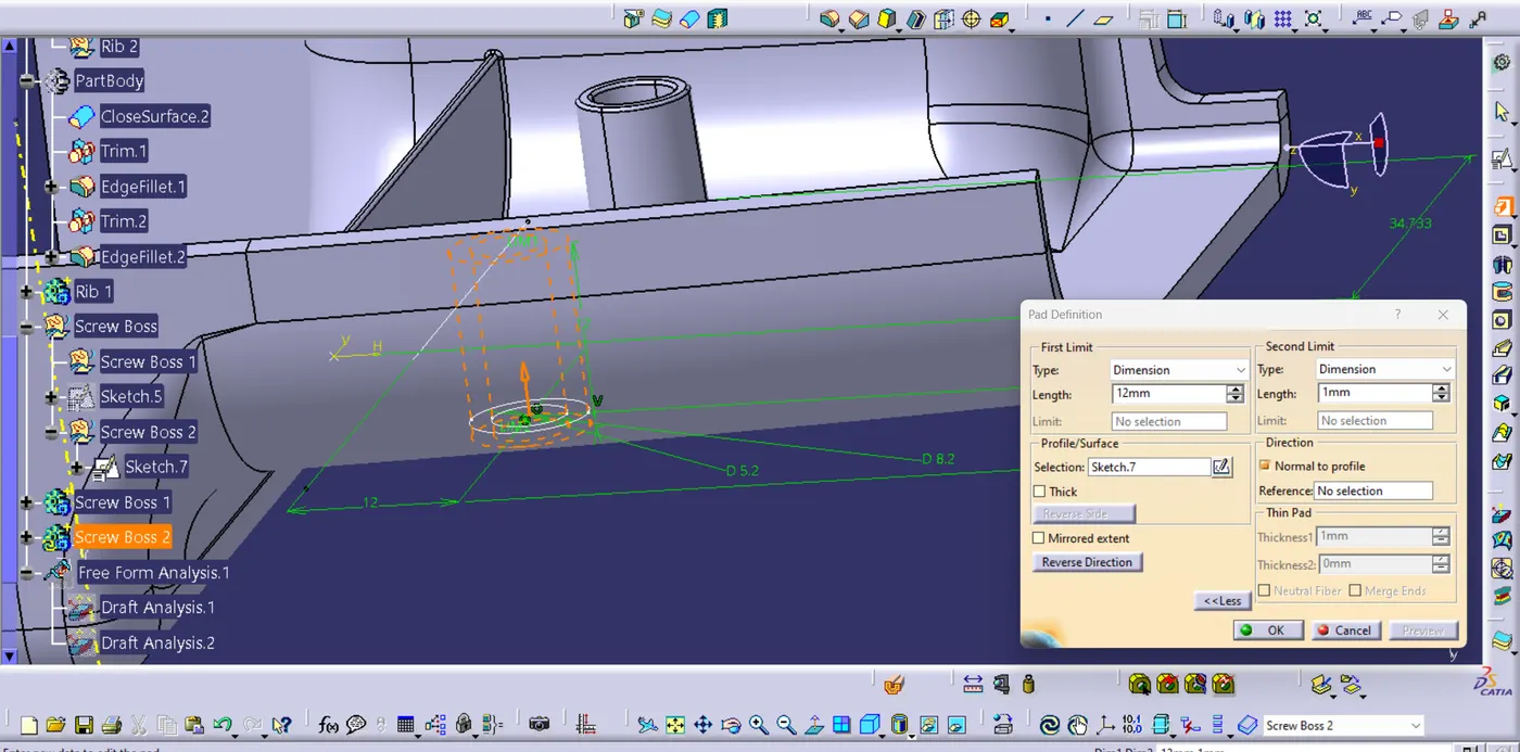
Now using pad command extrude the drawing
The height of the Screw boss should be less than 3 times the outer diameter of the Screw boss
= < 8>
= < 24>
The height of the scew boss is = 3 * Thickness of surface
= 3 * 2.5
= 7.5 mm
So here lets take it as 12 mm
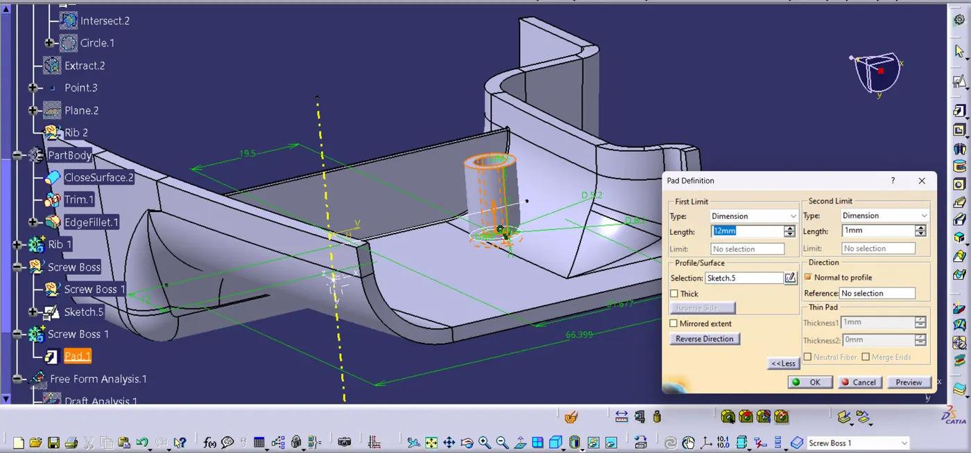
- The draft id given for inside and outside of the screw boss wchich is 0.5 mm
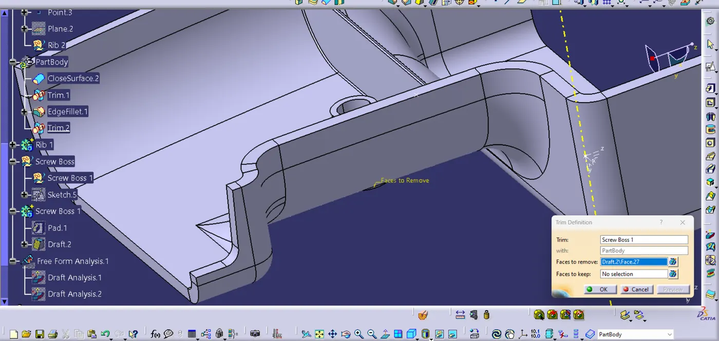
- Then Union trim it with the main body
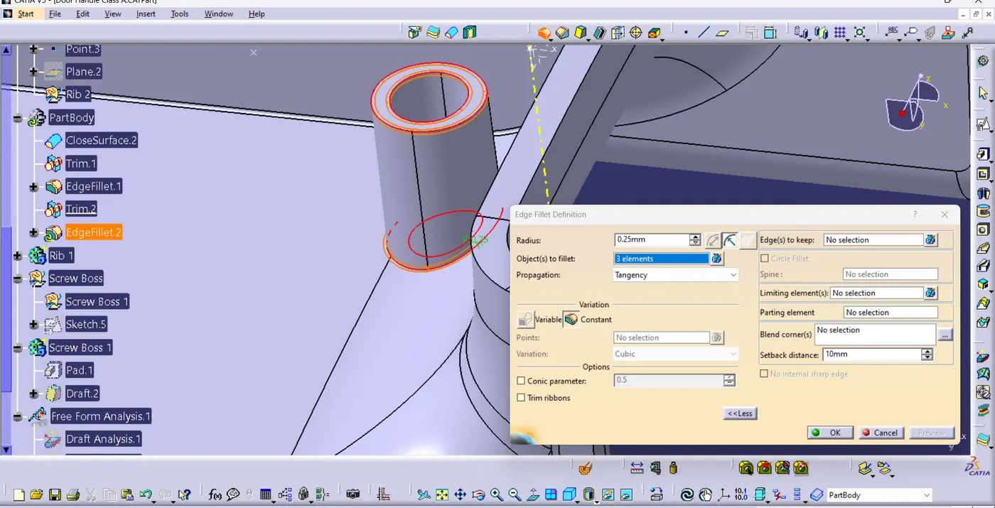
- Then give edge fillet of 0.25 mm
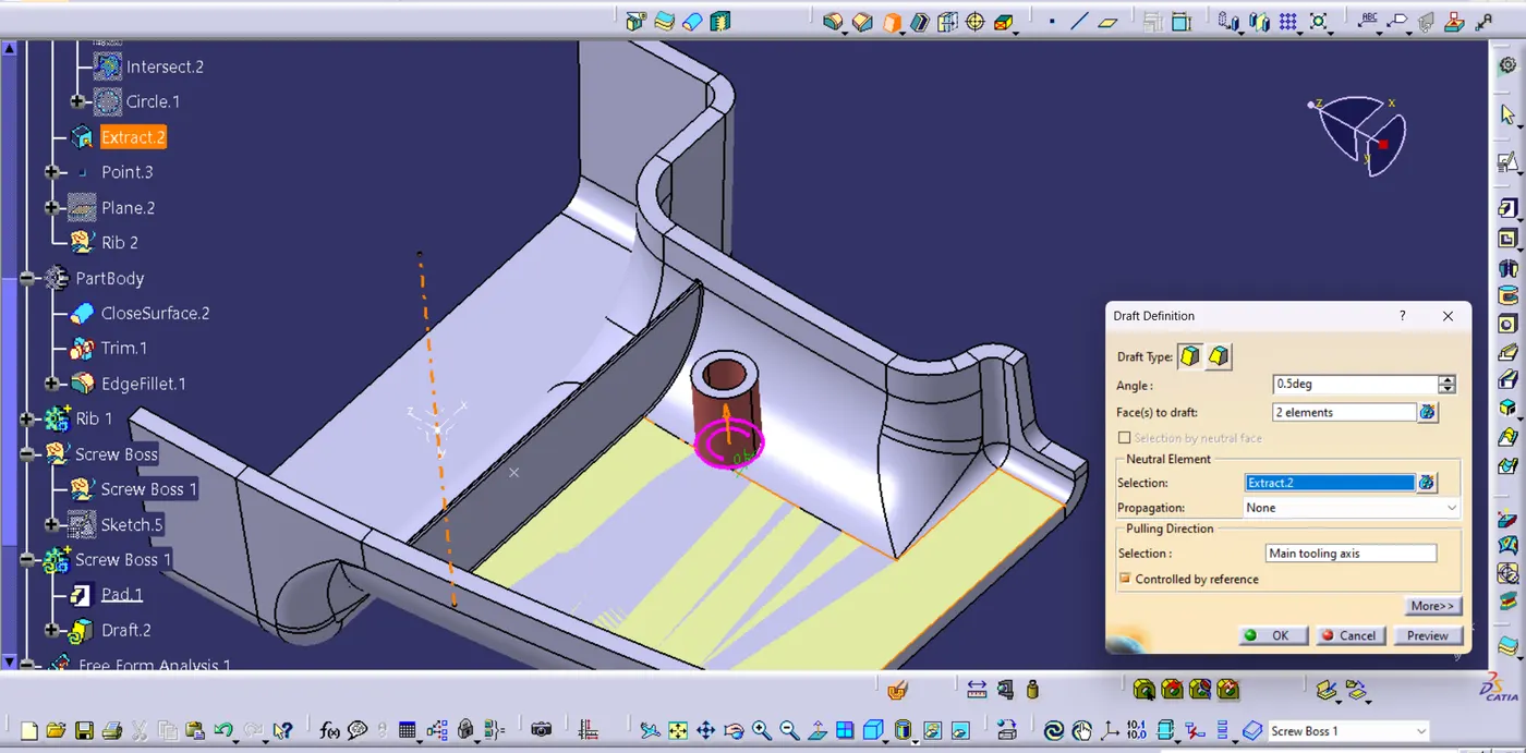
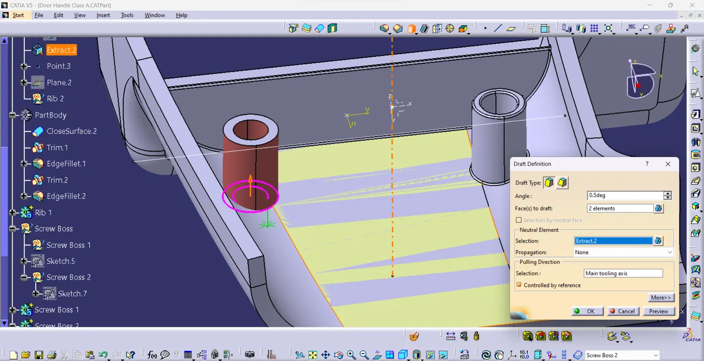
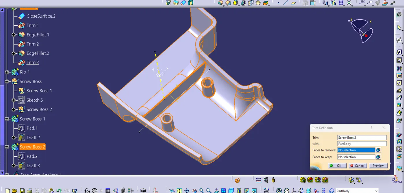
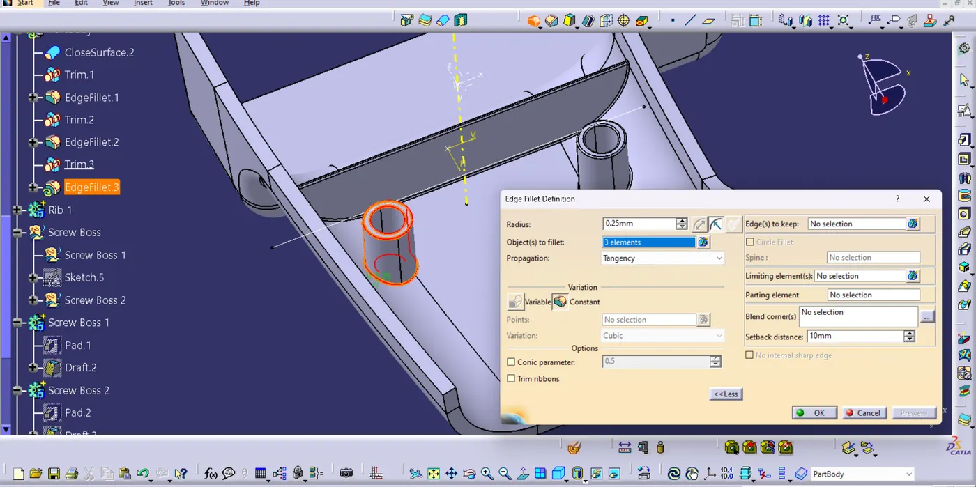
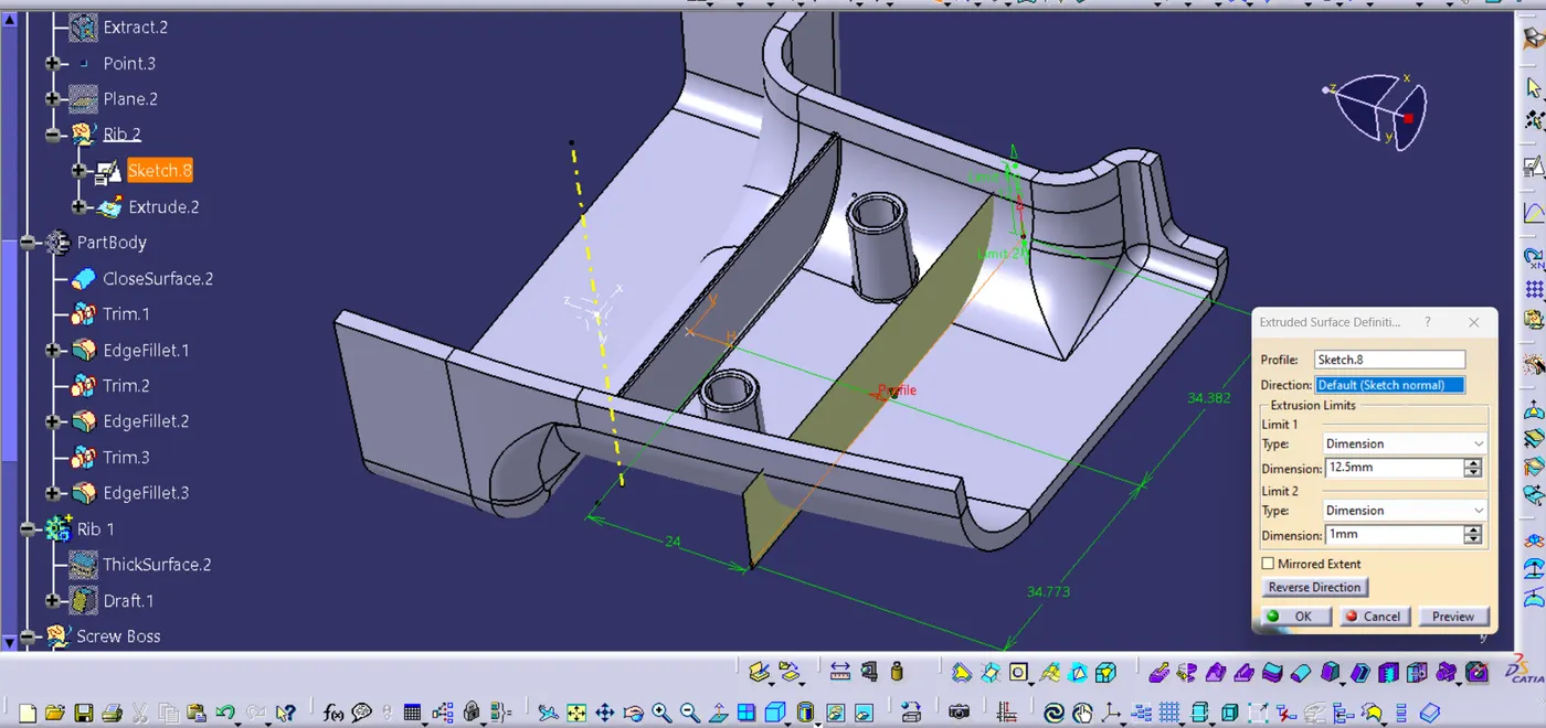
Step 9 : Next the Rib 2 need to be made and the distance between the screw boss and rib should be minimum of 3 times Wall Thickness
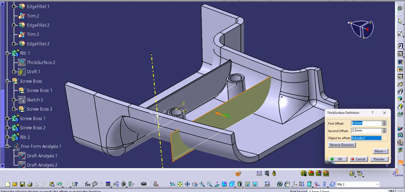
- Create the line in the plane and then extrude it
- Then after inserting a body pad the surface and then give the draft of 0.5 degree.
- Using union trim join the part to main body
- Then provide the requied fillet which is of 0.25 mm
Final Draft analysis
Front View
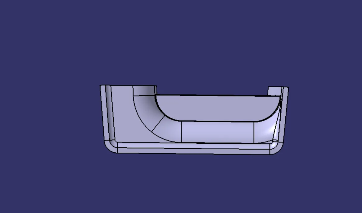
Top View
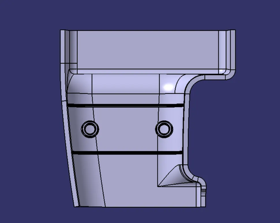
Left side View
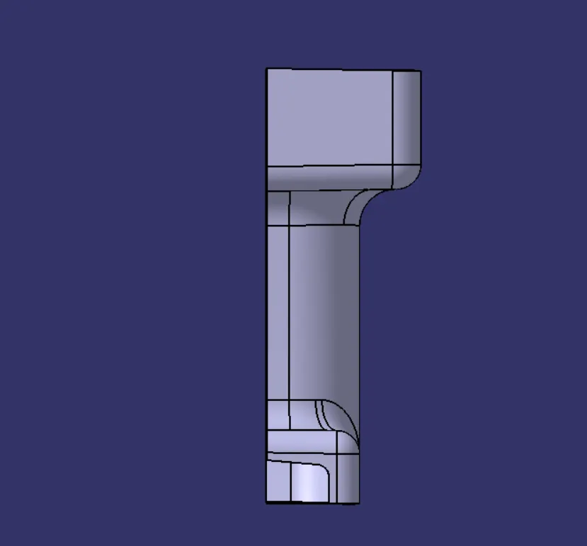
Right Side View
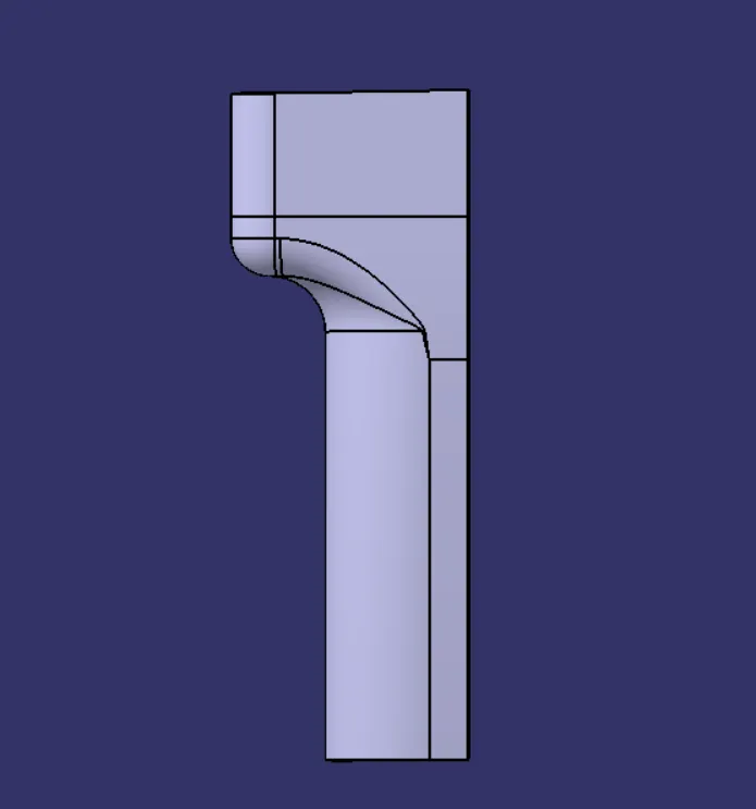
Bottom View
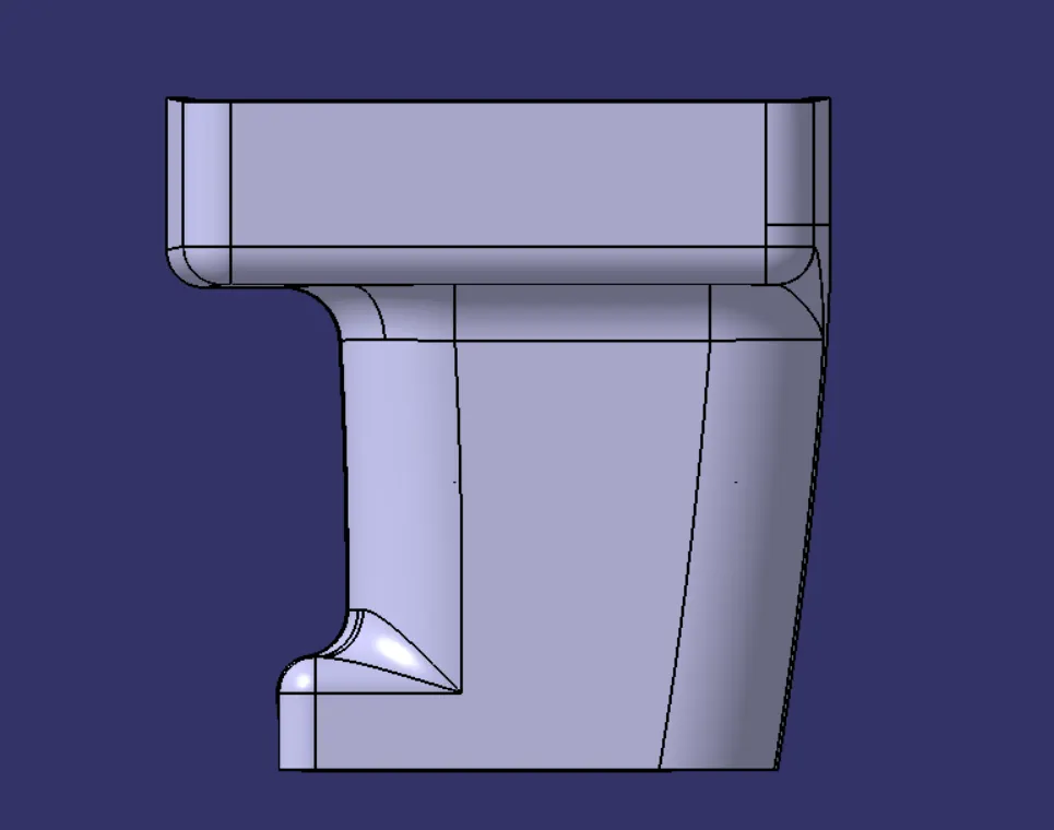
Isometric View
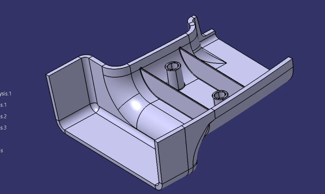
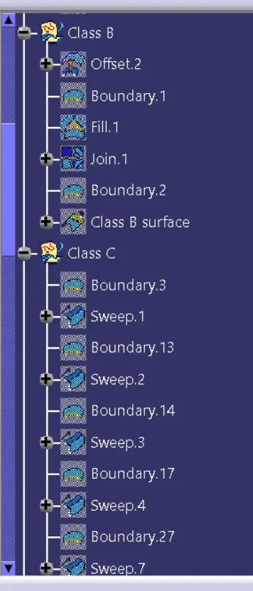
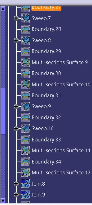
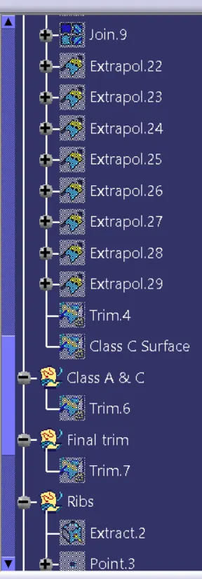
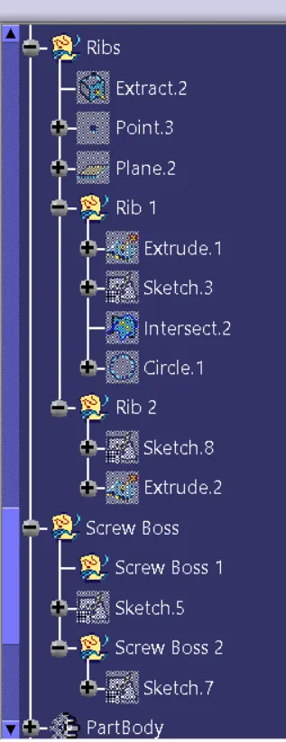
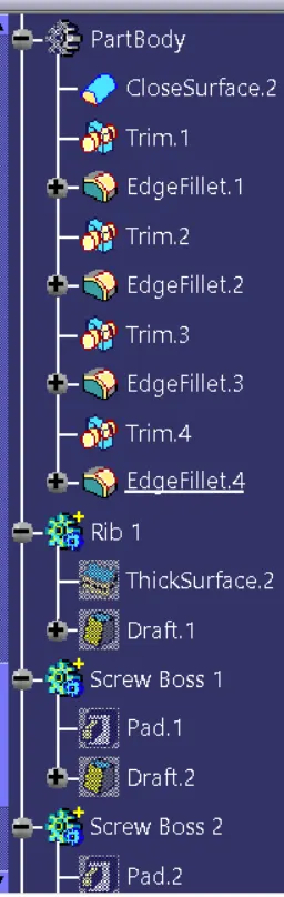
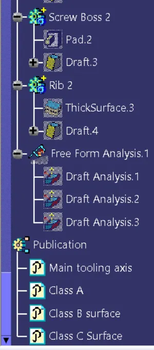
Tree Structure
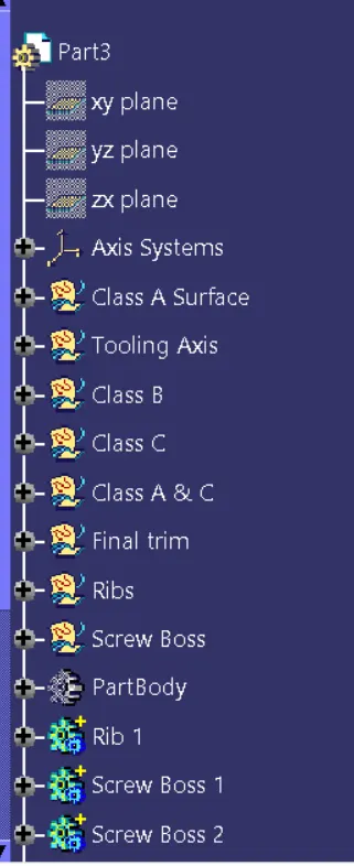
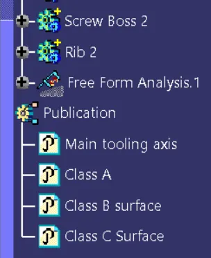
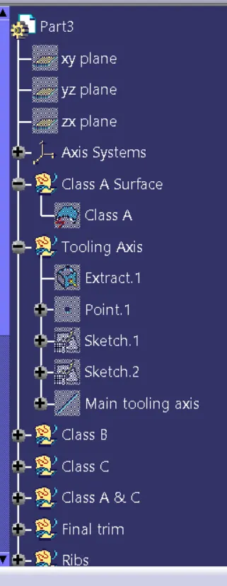
CONCLUSION
- Created the rib for the Drill Handle considering the design rules.
- Created Screw boss for the Drill Handle considering the design rules.
- From the final draft analysis it is clear that the Class A surface has to be modified for getting proper tooling axis and hence for good workability