Fender Design
AIM
To design a car fender with it's mounting according to the master section and engineering standards.
THEORY
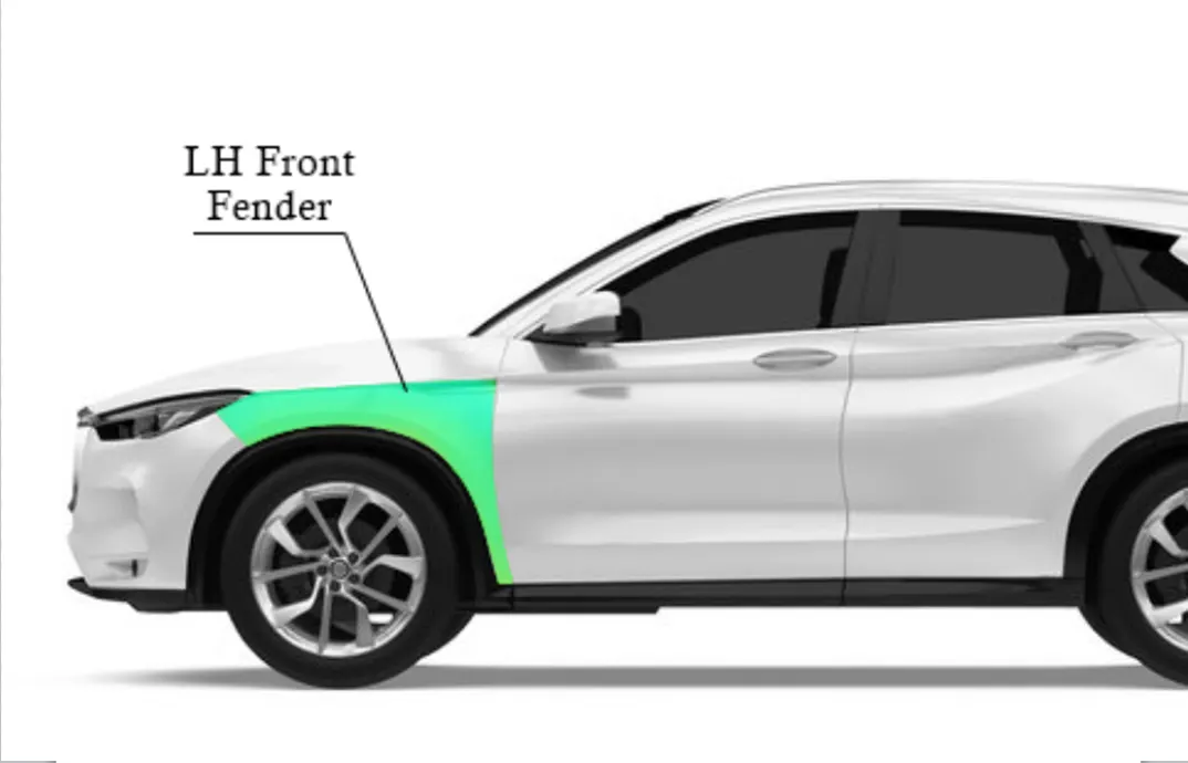
Fender
A fender is typically made of metal or plastic and is located at the front and rear of the vehicle, covering the wheel wells and surrounding areas.
One of the main functions of a car fender is to protect the vehicle and its occupants from road debris, dirt, and water that may be thrown up by the rotating tires.Fenders often provide mounting points for side-view mirrors and turn signal lights.
Fenders help prevent these materials from hitting the body of the car, which can cause damage and corrosion over time.Fenders are designed to provide structural support to the vehicle's body, particularly around the wheel arches. They help maintain the car's overall rigidity and structural integrity, which is important for safety in the event of a collision.
Fenders are designed to absorb and distribute impact forces in the event of a minor collision or contact with another object. This helps minimize damage to the vehicle and reduce the risk of injury to occupants.
Fenders can also be aerodynamically designed to improve a car's fuel efficiency and reduce wind resistance. By shaping the fenders to direct airflow around the wheels and body,the car's overall performance can be enchanced.
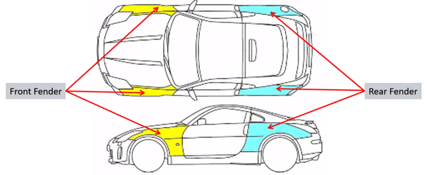
Types of Fenders :
- Full bumper type
- Half bumper type
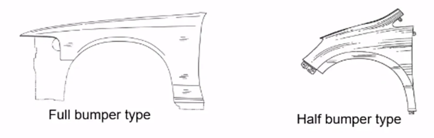
Full Bumper Type : These types of Fenders are used in the old car models.It requires larger sheet metal which increases the weight of the component.As the material requirement is more the wastage during the manufacturing process is also high,which increases the cost of the component also.
Half Bumper Type : Half fender type is modern design where less material consumption is observed,so productivity increases by reducing size of blank and thus providing more The maintenance also relatively low compared to full bumper type.
Mounting Areas of Fender
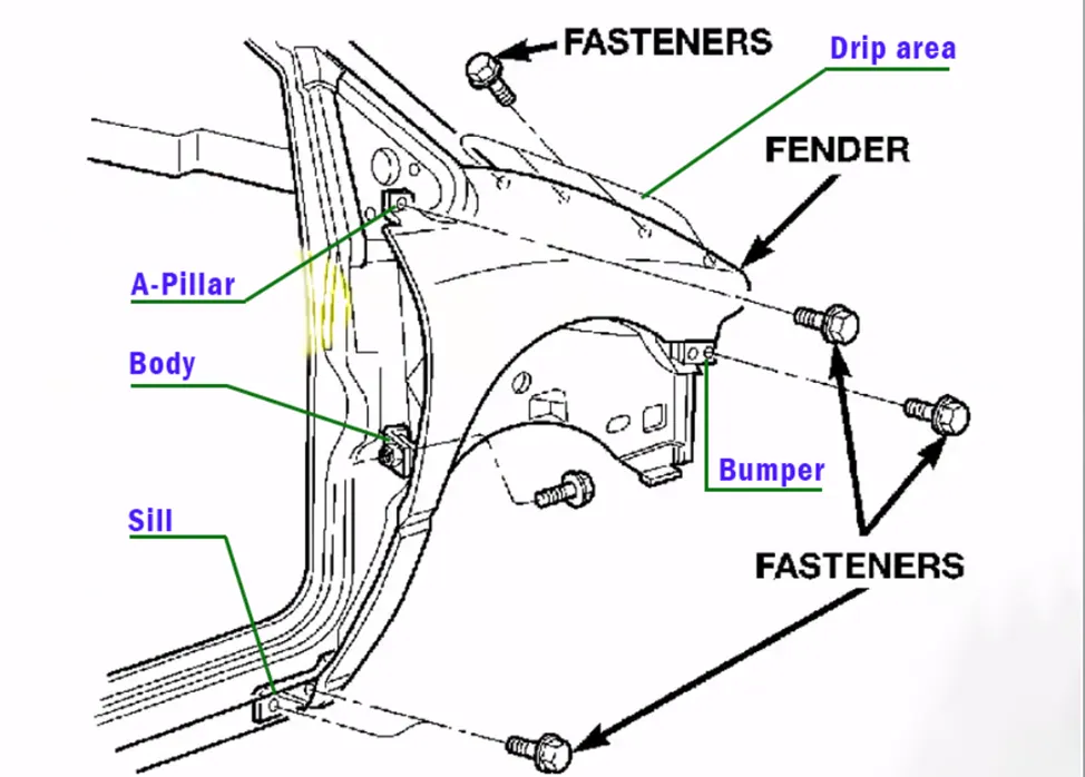
There are 5 mounting areas for a fender :
- Drip mounting
- A- pillar mounting
- Body mounting
- Sill mounting
- Bumper mounting
Given master section of the DRIP AREA :
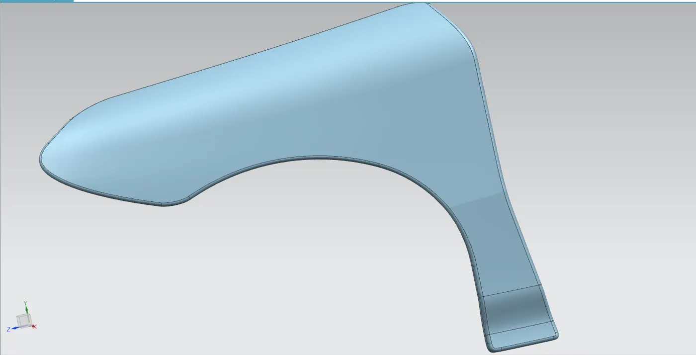
Given Class A surface / Skin Data :
PROCEDURE
Using curve on surface, offset curve in face and trim, sketch the flange area and trim the extra flanges.
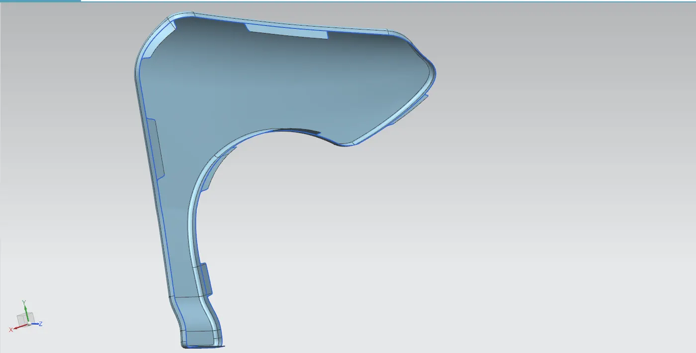
1. Drip Mounting Design :
- The drip area is the point where the fender is attached to the engine compartment.
- The drip area should be designed in such a way that it should be at least 150mm away from the front end of the fender to have sufficient space for mounting headlamps housing.
- Mostly the drip area starts from 200mm away from the rear end of the fender, to have sufficient space for the cowl which carries the wiper equipment.
- The length of the drip area depends on the length of the fender.
Using law extension create the mounting areas :
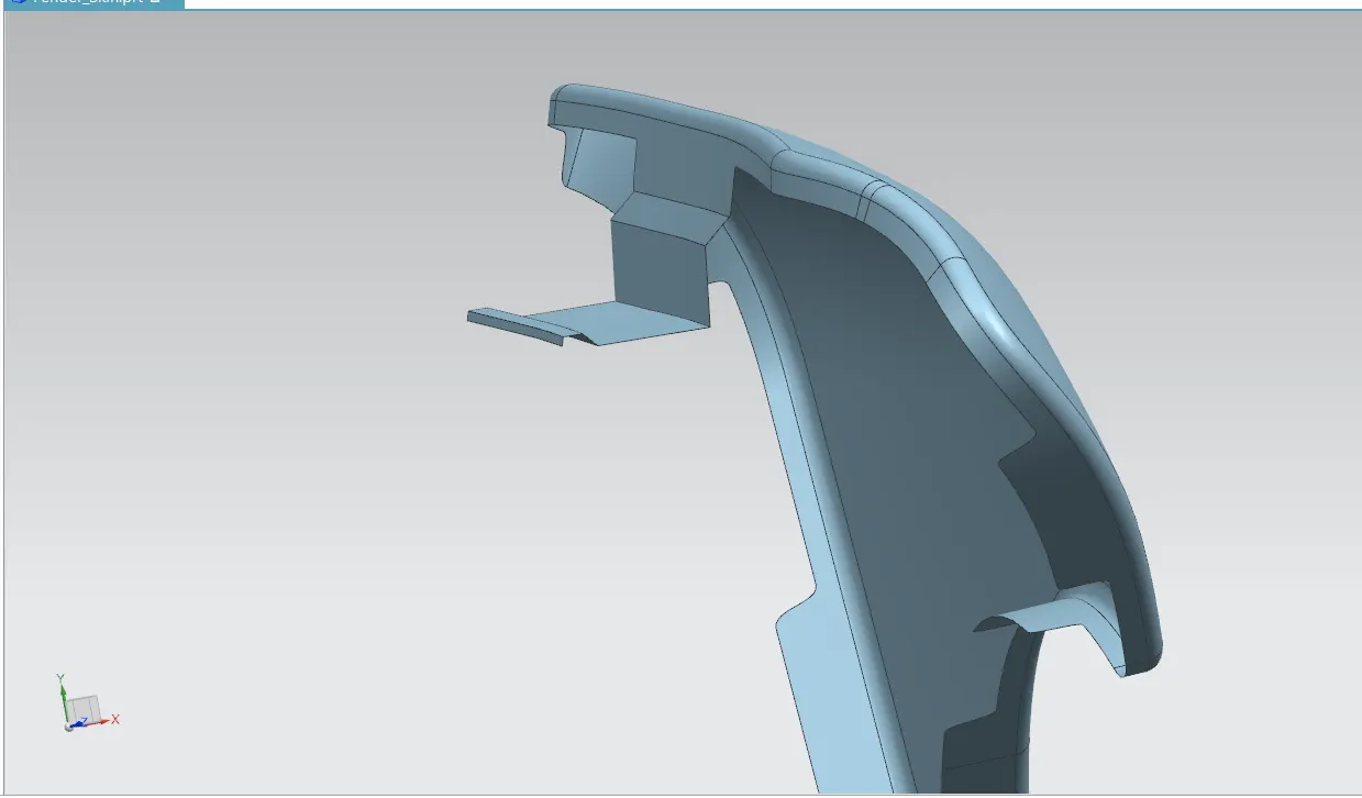
After creating the mounting area give the fillets according to the master section using face blend :
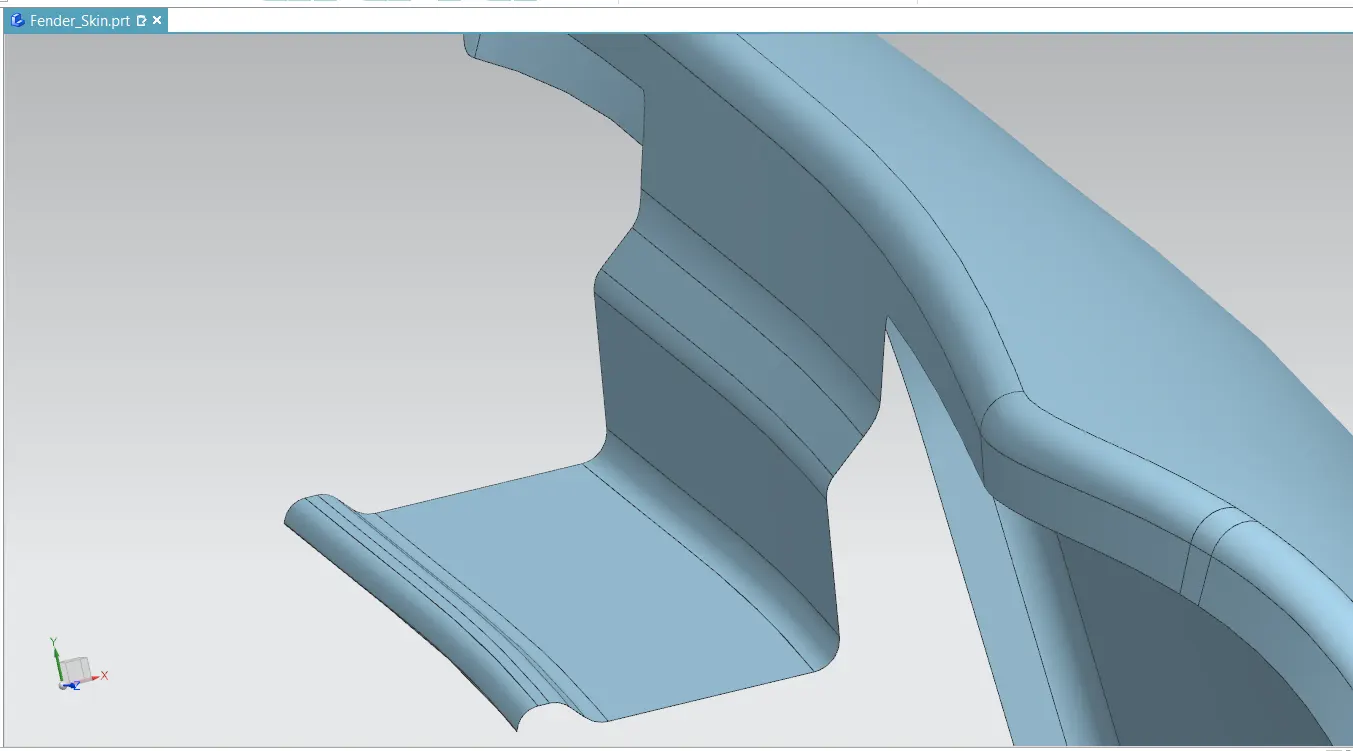
Make sketch for the area where the fastening are going to be placed and then give emboss to the sketch.Once the emboss is given make holes for the fastenings and provide edge fillets :
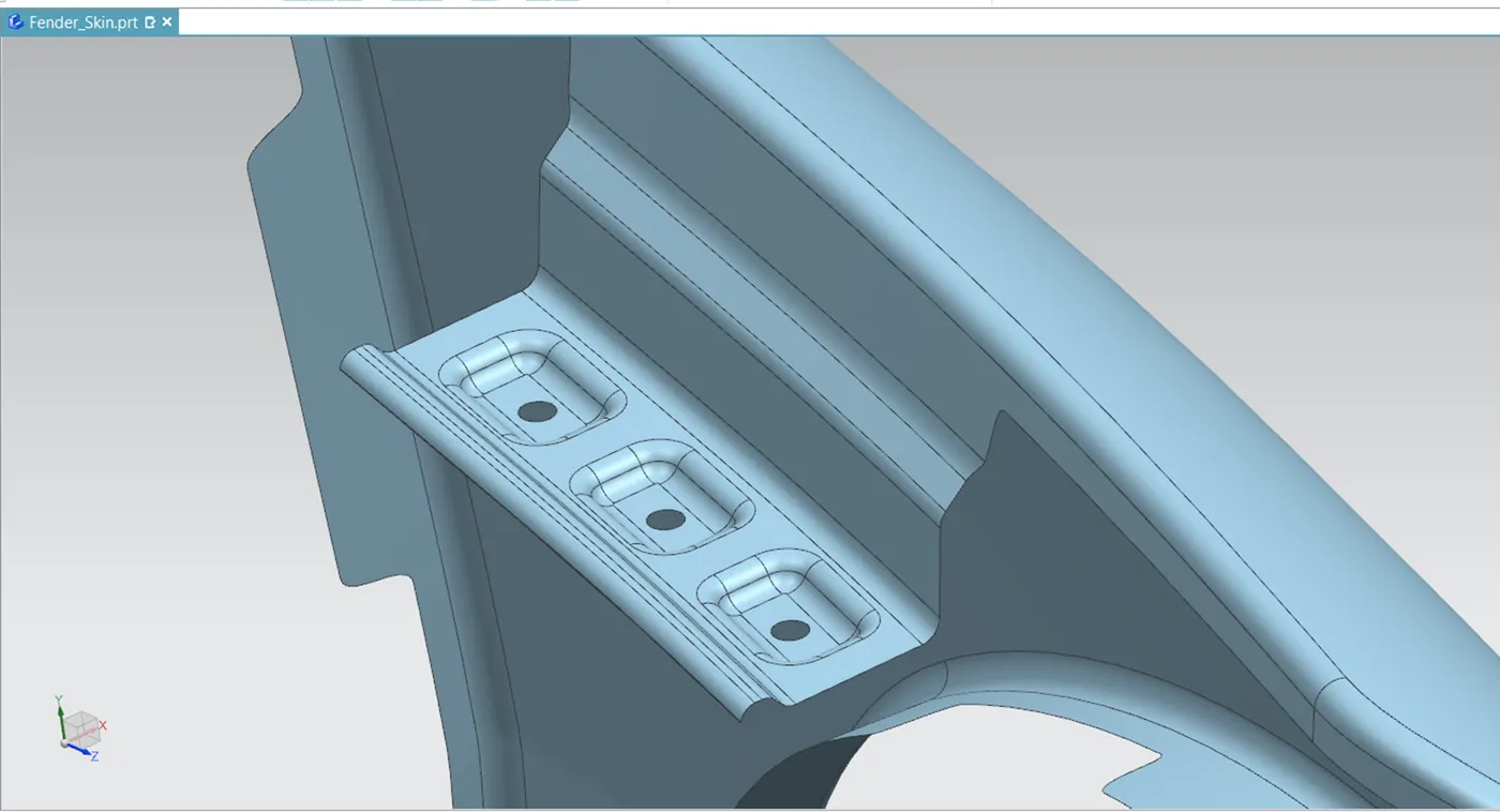
Two darts are added on the drip area in order to provide the stiffness and adds strength to the part . This will reduce the fender vibration and impact the forces outside of the fender during motion of the vehicle.
2. Sill Mount Design
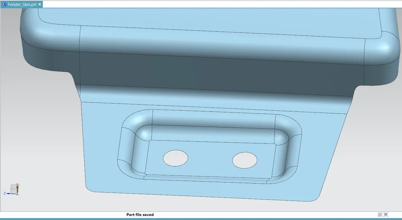
The sill is the panel below the bottom of the door supporting the floor and it is used to connect the floor and the body. The bottom end of the fender is mounted on the sill body for reinforcement of the fender panel. Here M5 fasteners are considered to fix the fenders on the sill body.
Extent the flange using law extension and create sketch for emboss and fastening hole.
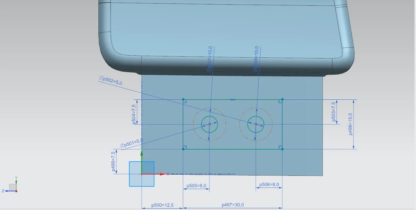
After sketching create the emboss, holes and fillets
3. Body mounting Design :
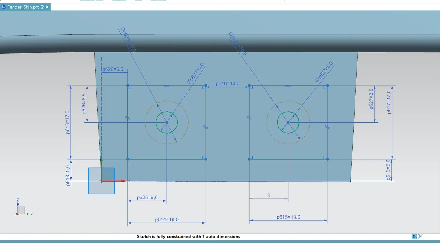
The body mounting connects the fender with the door area.
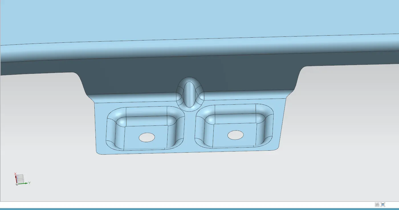
The flange is extented to required lenght and then the sketch are drawn for accommodating M5 fasteners with emboss and fillets.
After sewing the flanges provide rib using dart command
4. Bumper Mounting Design
The bumper mounting point is created for attaching the bumper to the fender using fasterners.
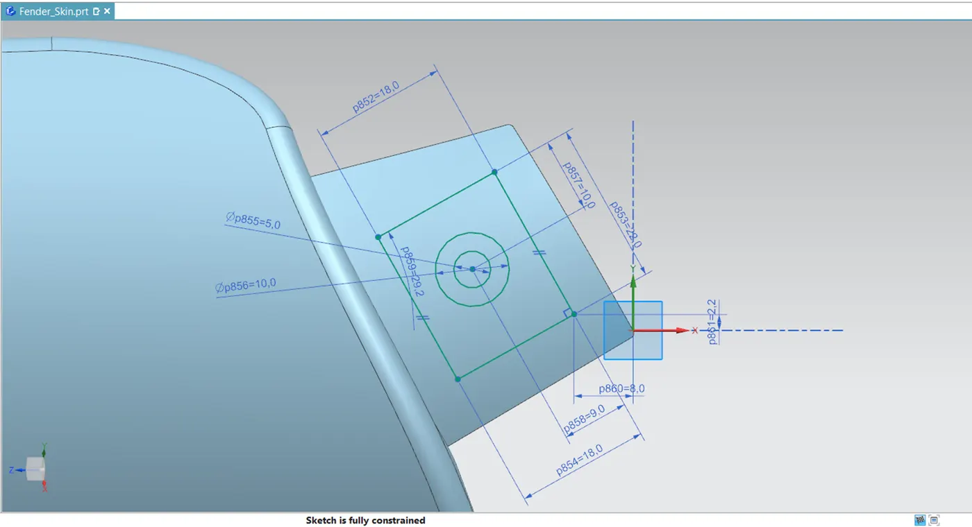
The flange is extented to required lengthe and sketching is done for embossing and fastening hole,later the edge fillets were provided.

5. A-Pillar Mounting Design :
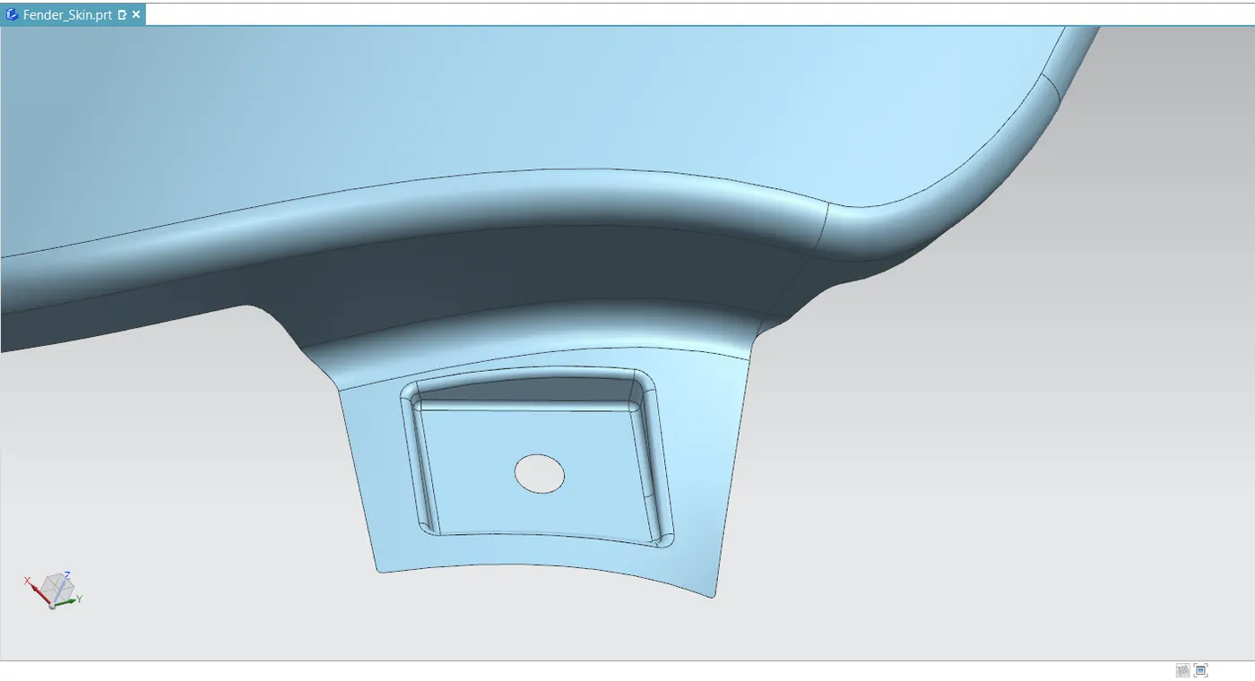
The A-pillar is the structural pillar that combines the body with the roof .This mounting position is created for attaching the fender to A Pillar of the vehicle.The mounting has to be created by taking the reference from the A-pillar of the vehicle.
Baffle Mount area design
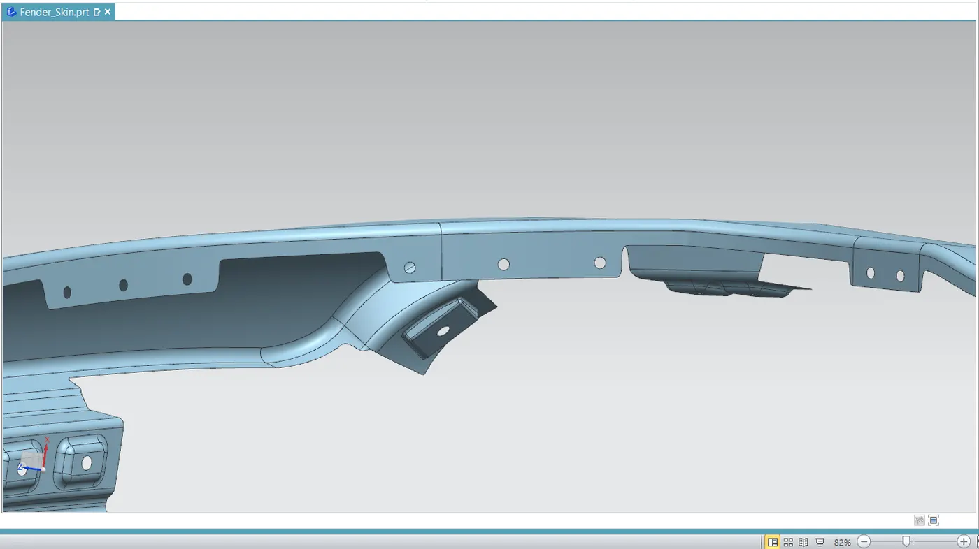
Baffle mounting or mudguard are clip fit type of mounting on the inner side of the fender arch over the Tyre . It protects the car engine compartment and pedestrians from causing injuries from chip out debris on the road when the car is in motion. They are mounted on the fender using a special type of locking clips which are made up of plastics.
The baffle mounting holes were created by sketching and then using pattern feature
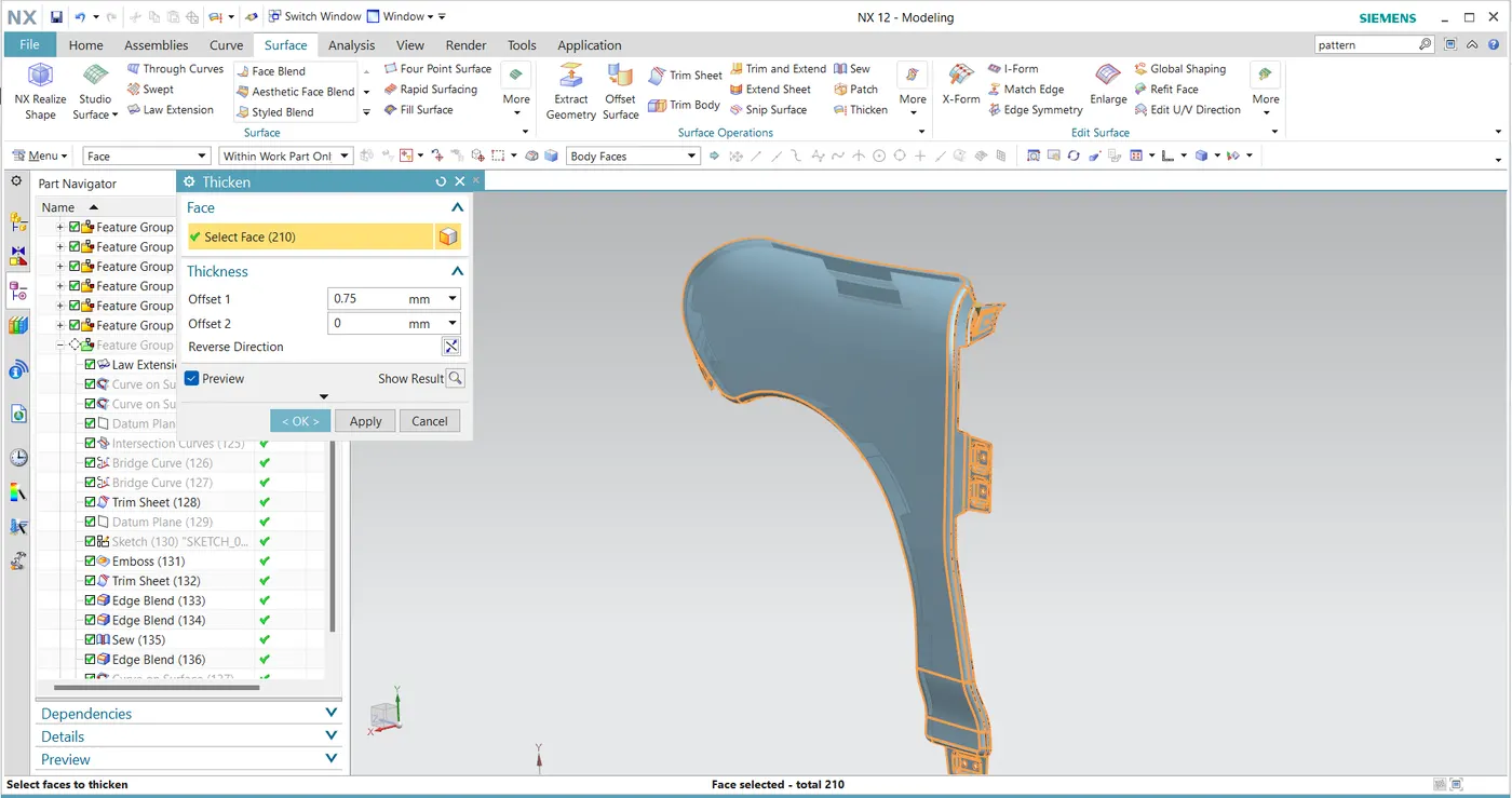
Thickening the surface
A thickness of 0.75 mm is given as thickness for the surface to make it a solid metal sheet.
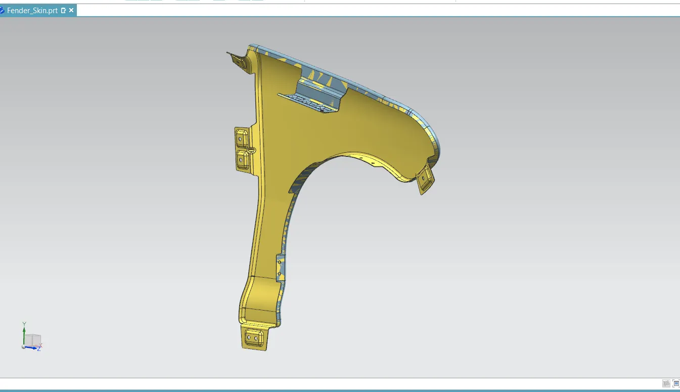
Top view
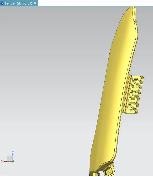
Front View
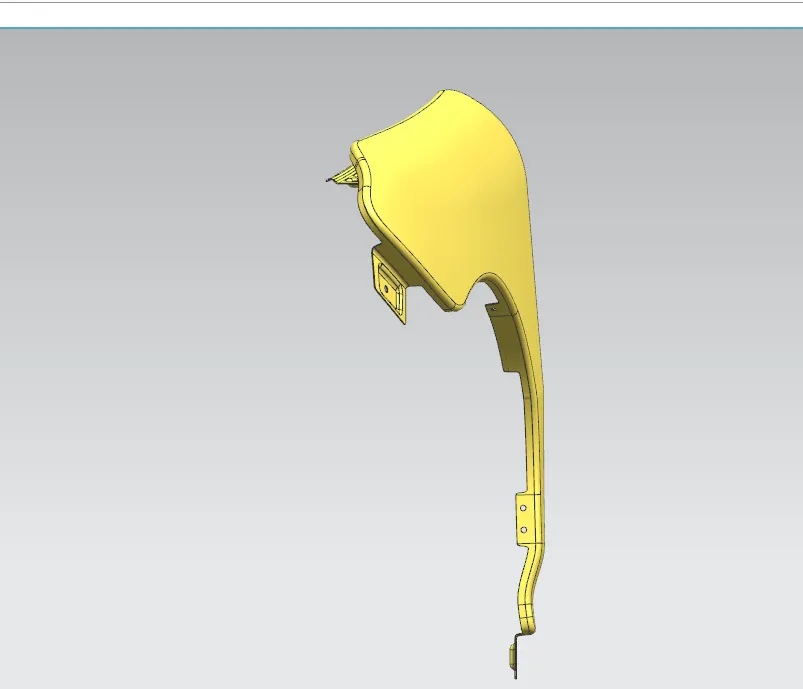
Right side view
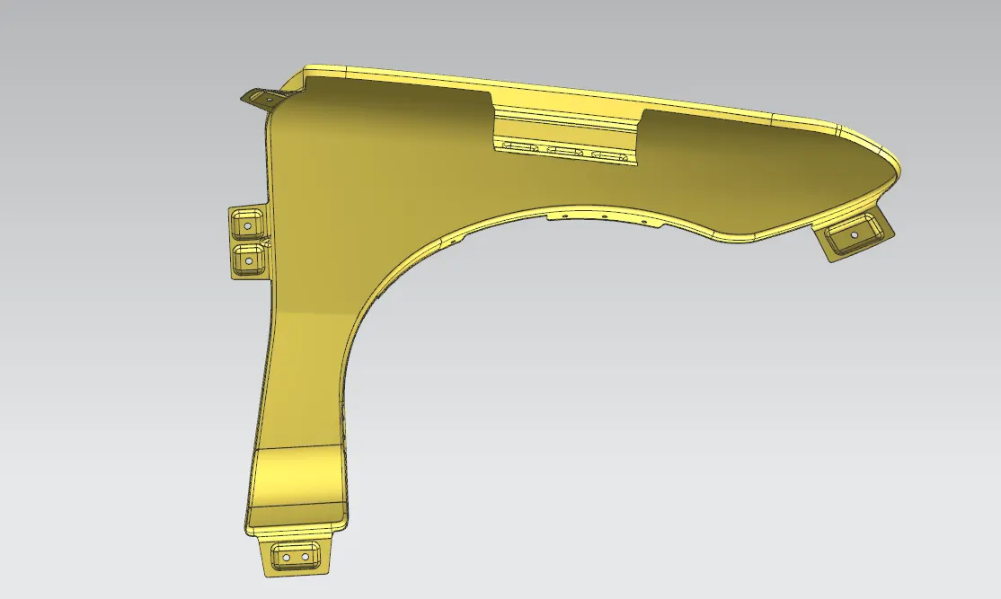
Left side view
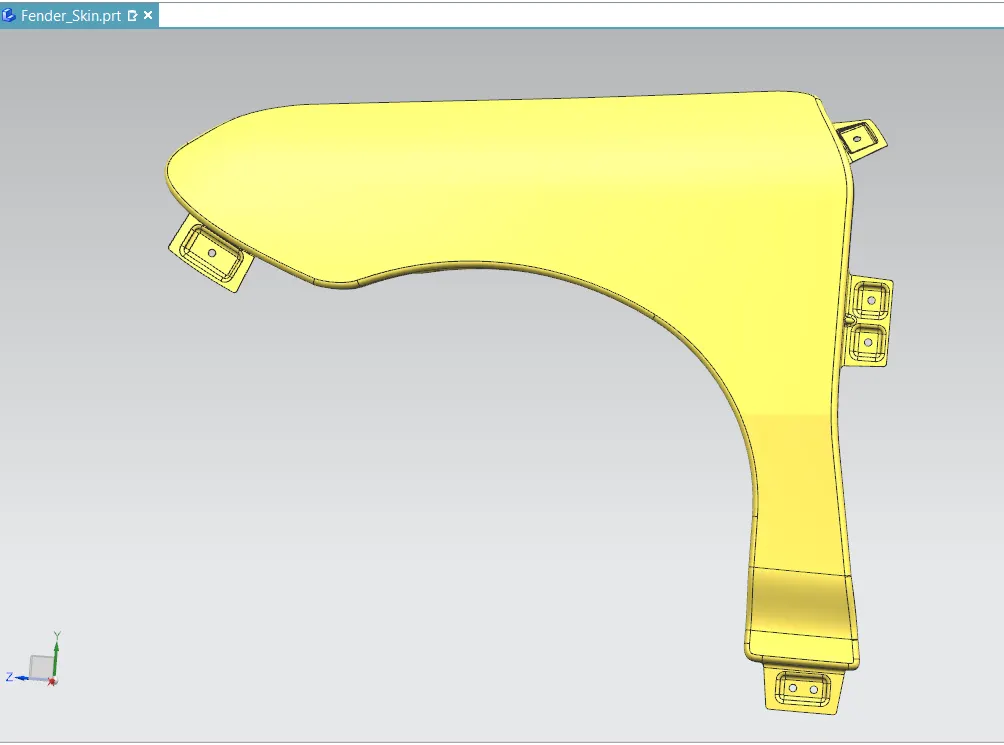
Isometric View
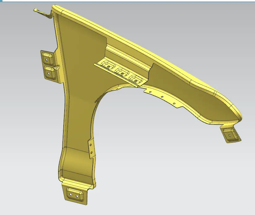
RESULT
- Designed a car fender with it's mounting according to the master section and engineering standards.
- Then converted to metal sheet of 0.75 mm thickness