Week 10 - Challenge 3 - Door Trim Lower with Engineering Features
AIM
To create the Door Trim Lower Plastic component through the given Class-A surface.
THEORY
Tooling axis
The tooling axis in plastic injection molding refers to the direction in which the two halves of the mold, the core and cavity, separate or come together during the molding process. It is a critical consideration in design because it influences the part's ease of ejection from the mold, the overall mold complexity, and the final part quality. Properly selecting the tooling axis ensures that the part can be efficiently molded, released from the mold without damage, and meets design specifications. The choice of tooling axis depends on factors like part geometry, draft angles, undercuts, and the desired surface finish, with careful attention needed to optimize the injection molding process.
Draft analysis
Draft analysis is the process of evaluating and measuring the angles or slopes incorporated into the surfaces of a 3D model or physical part. These angles are called "draft angles" or simply "drafts." Draft angles are designed to facilitate the easy removal of a part from a mold or die during manufacturing processes like injection molding or casting.t helps prevent issues like part sticking to the mold, surface defects, or increased production costs.
Class A surface
A Class A surface in simple terms is a very smooth and flawless surface on a product, often seen on things like cars or consumer electronics. It's like the shiny, polished exterior of a high-quality sports car, without any visible imperfections, bumps, or roughness. Designers and manufacturers work hard to create Class A surfaces because they give a product an attractive and premium look, making it more appealing to customers.
Class B surface
A Class B surface, in simple terms, is a surface on a product that doesn't need to be as perfect and flawless as a Class A surface. It might have some minor imperfections or less critical areas that don't need to be as smooth or visually perfect. Think of it like the less noticeable parts of a car, such as the inside of the door panels, where small imperfections are acceptable as long as they don't affect the overall functionality or appearance of the product. Class B surfaces are used to balance cost and manufacturing efficiency while still maintaining acceptable quality standards.
Class C surface
A Class C surface is a surface on a product where imperfections and roughness are more acceptable than in Class A or even Class B surfaces.These surfaces are usually hidden from view or not critical to the product's appearance or function.Class C surfaces are used to minimize production costs while meeting basic quality and functional requirements.
RIb
A rib is a thin, elongated structural element that extends from a surface or wall of a part to add strength, rigidity, or support without significantly increasing the part's thickness or weight. Ribs are often used to reinforce plastic or sheet metal components, and they help reduce material usage while maintaining structural integrity.
Doghouse
A doghouse typically refers to a recessed or specially designed area on a mold or die where specific features or components, such as inserts or ejector pins, are housed or placed. It helps ensure that these elements are properly positioned and do not interfere with the molding or forming process. Doghouses also make it easier to maintain and replace these components.
Locators
Locators are components designed to precisely position and align parts during assembly or manufacturing processes. They ensure that parts fit together accurately and consistently, reducing assembly errors and improving product quality. Locators can include pins, holes, slots, or other geometric features that serve as alignment points.
Heat Stakes
Heat staking is a joining process used in manufacturing to fasten two components together by melting and forming a portion of one component to capture or engage with features on the other component. This is typically done using heat and pressure to create a secure mechanical bond. Heat stakes are often used in the assembly of plastic parts, such as securing connectors or fasteners.
PROCEDURE
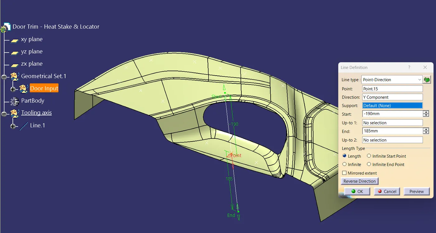
Step 1 : Creating tooling axis
- Insert a geometrical set for creating tooling axis
- A line was made in Y direction using line command with point and direction along the Y direction. Which will be considered as the main tooling axis after draft analysis
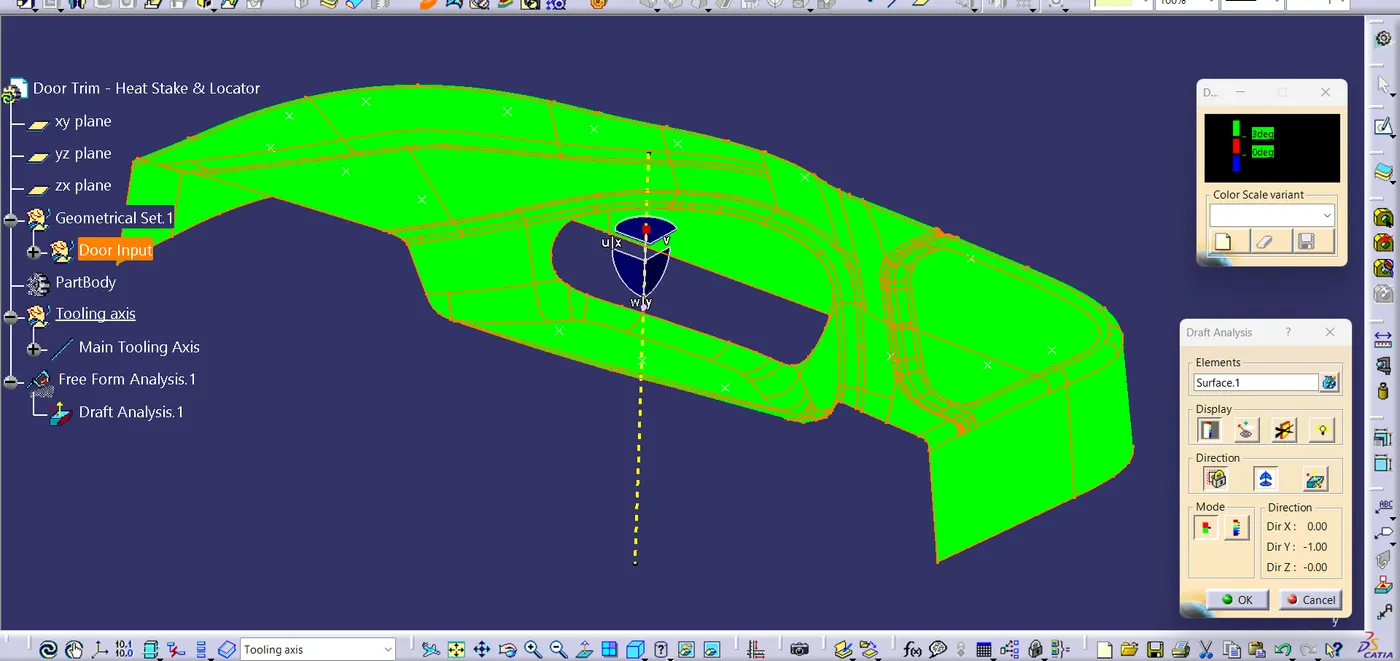
- Then the draft analysis is carried out on Class A surface and confirmed the tooling axis is clearing a draft of 3 degree in all the areas.
- Publish the Main tooling axis and Class A surface.
Step 2 : Creating Class B surface.
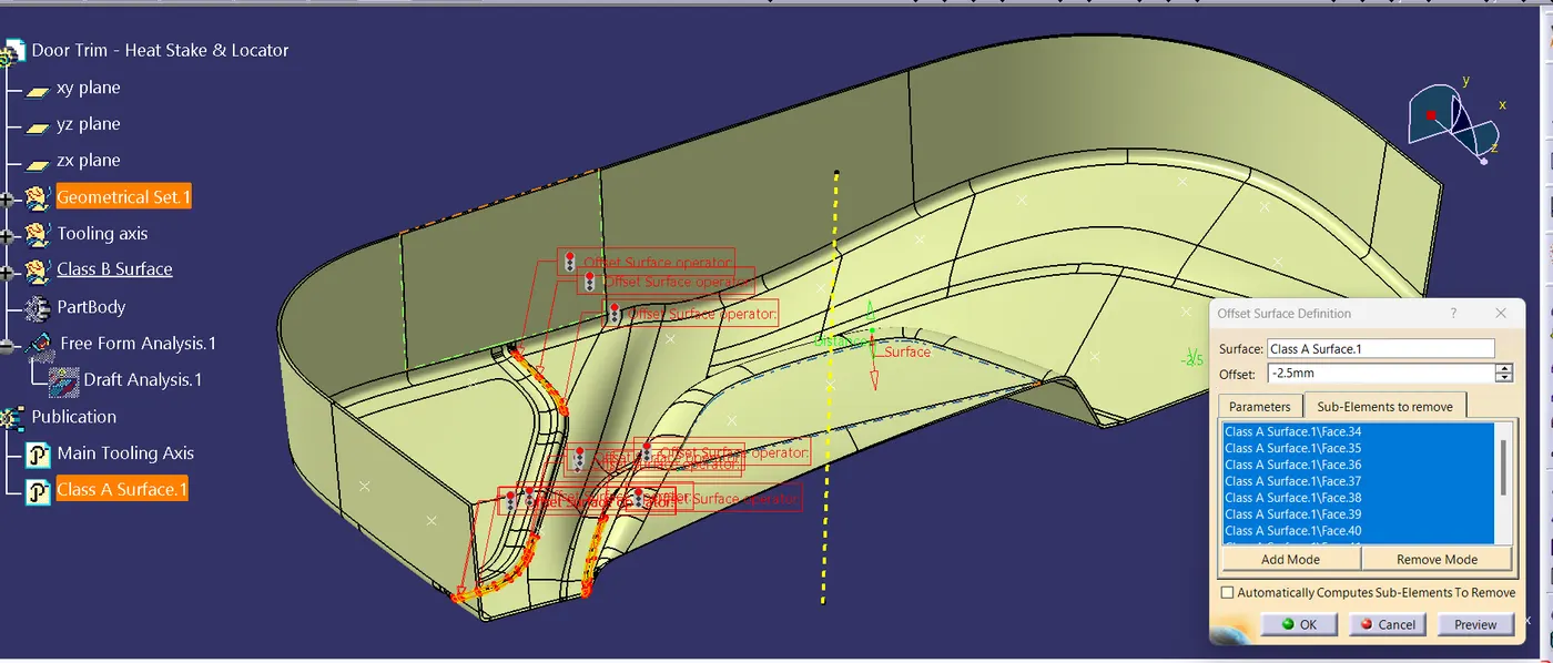
- For creating class B surface insert another geometrical set and Using Offset command Offset the class A surface 2.5 mm towards class B.
- The thickness of the component is considered as 2.5 mm
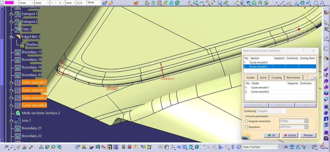
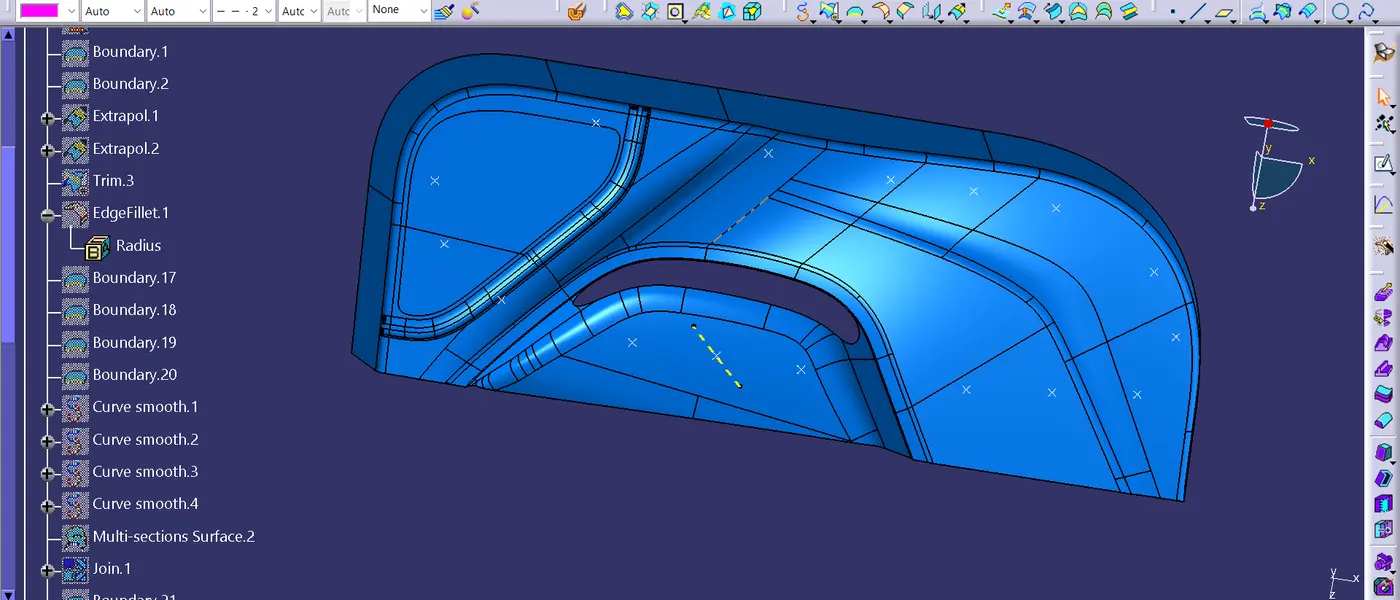
- Once offsetted we can find many missing patches, clear the patches using tools like extracting, trimming, joining and multi section surface.
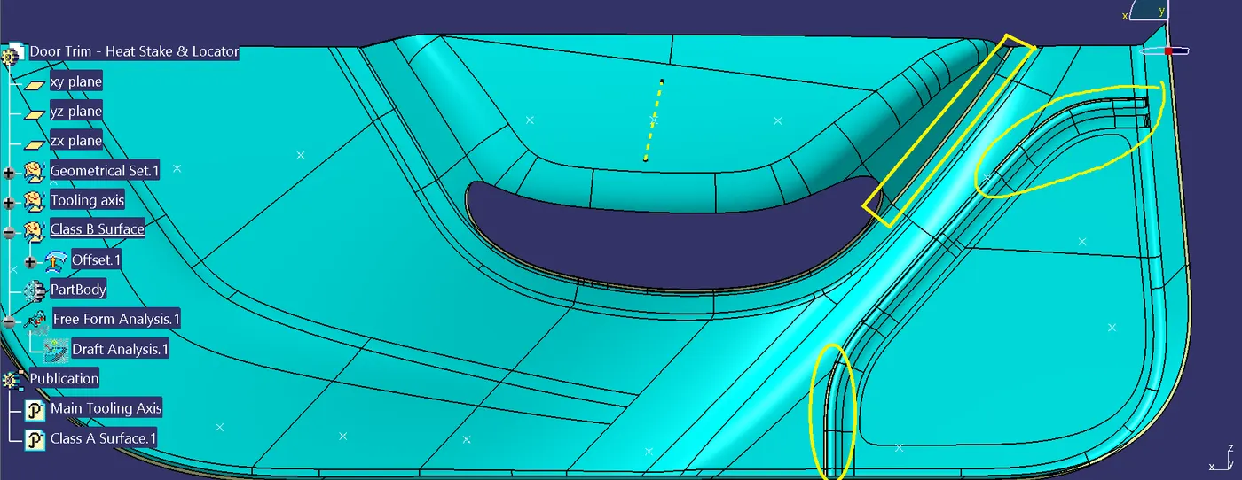
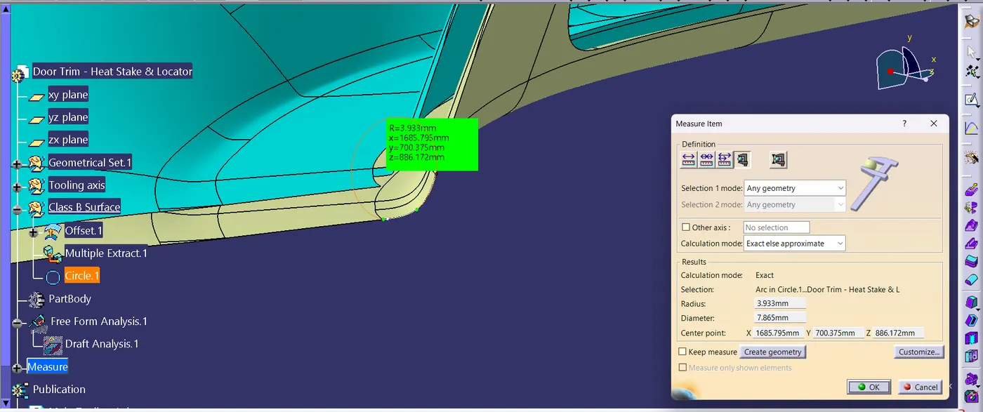
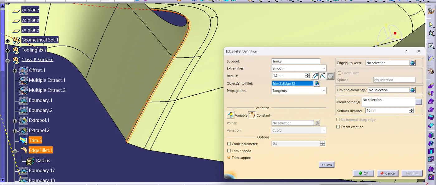
Here we found out the fillet radius which is 4 mm so for class B it will be 4 - 2.5 = 1.5 mm fillet.
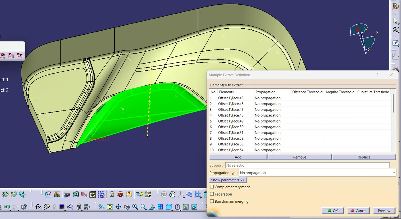
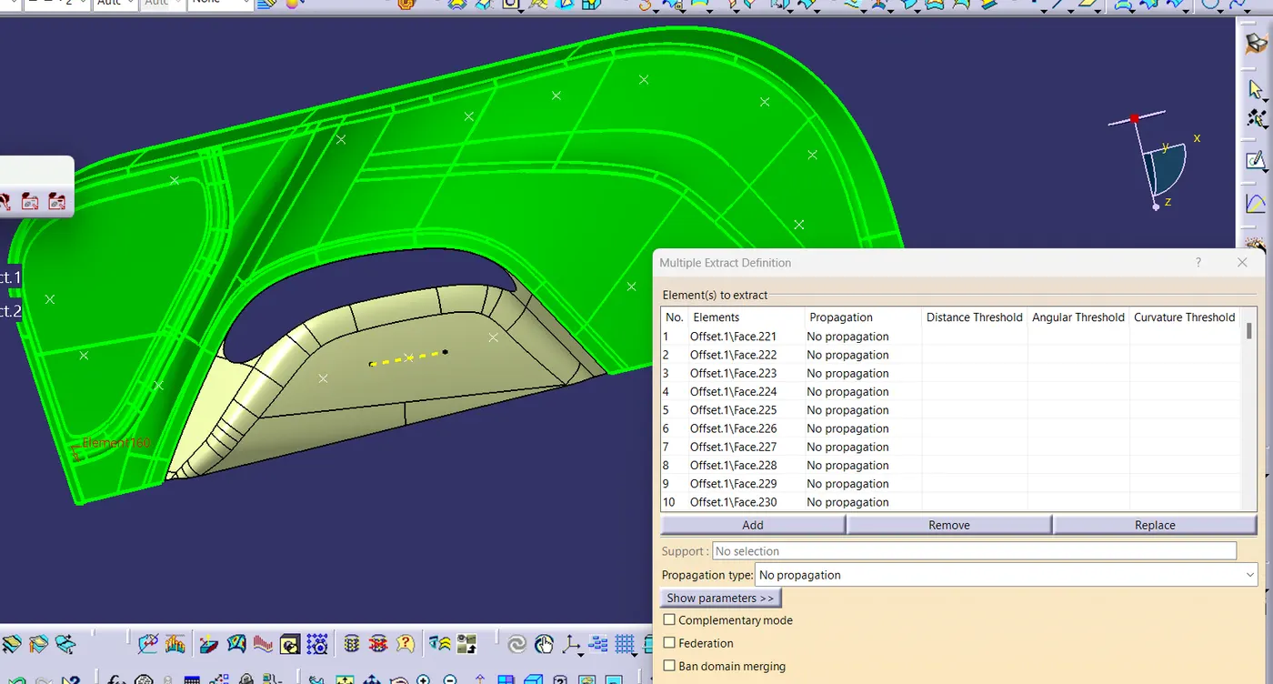
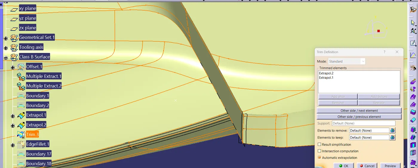
Step 3 : Creating Class C surface
- Insert a geometrical set for class C surface.
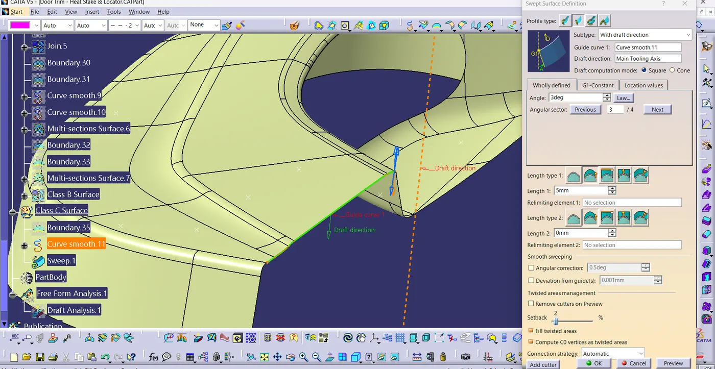
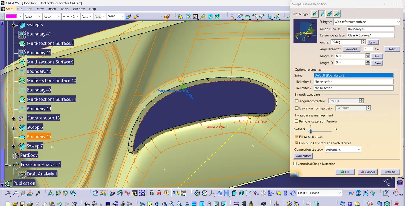
- Extract the boundries and using sweep command make the class c surface with tooling axis as draft direction and 3 degree draft.
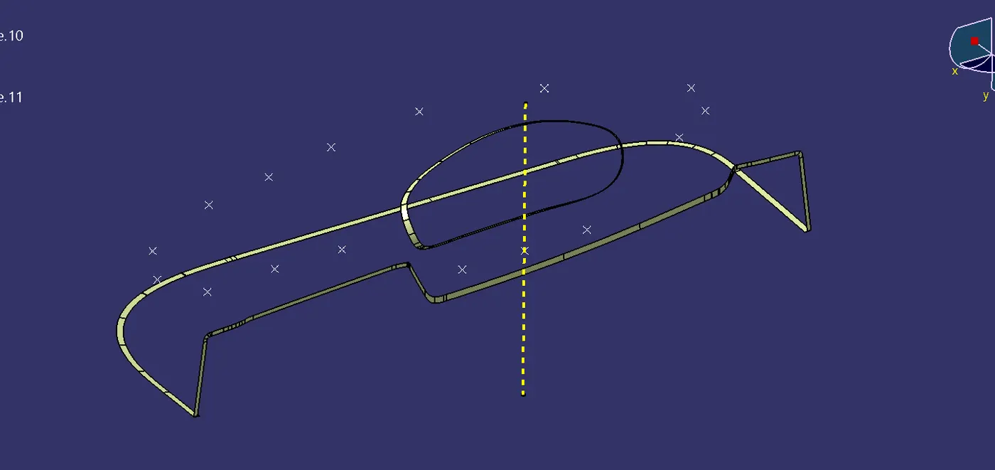
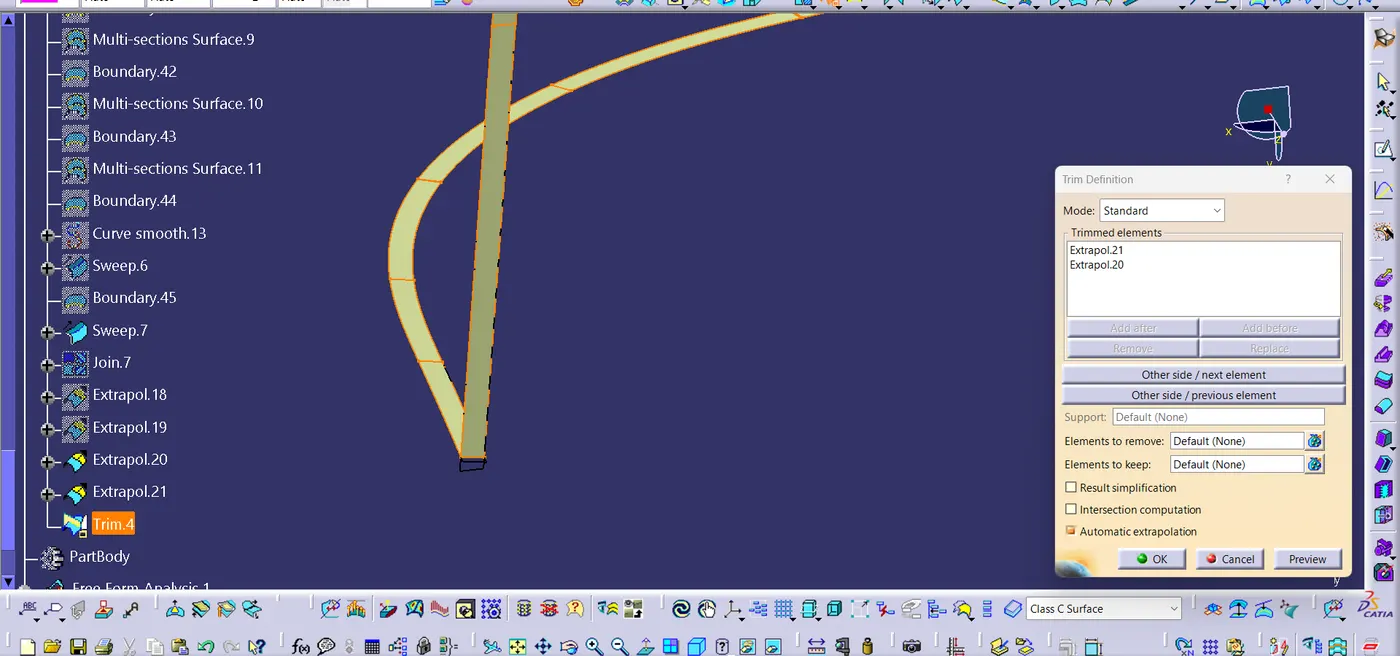
- After creating the sweeps using trim command join all the sweep to get Class C surface.
- Join the class C Surface with Class A with with we trim the Class B surface to get closed body.
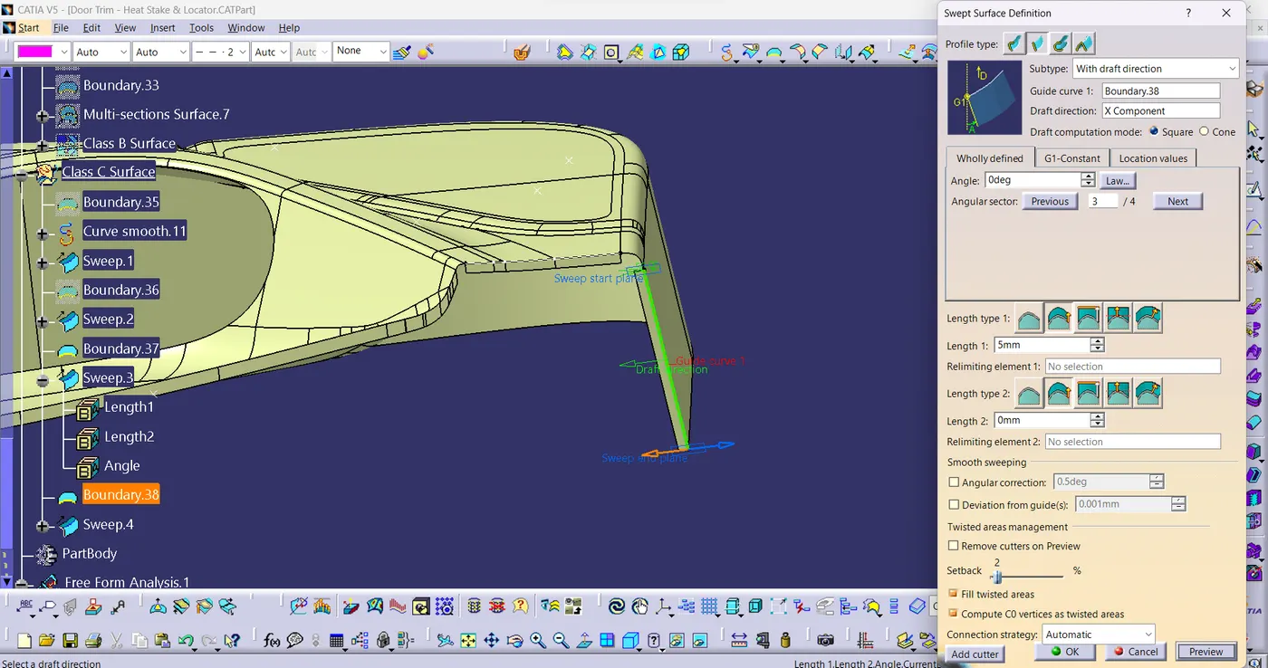
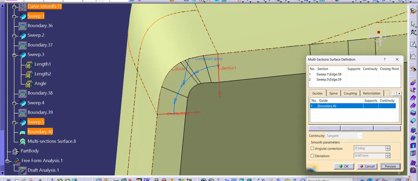
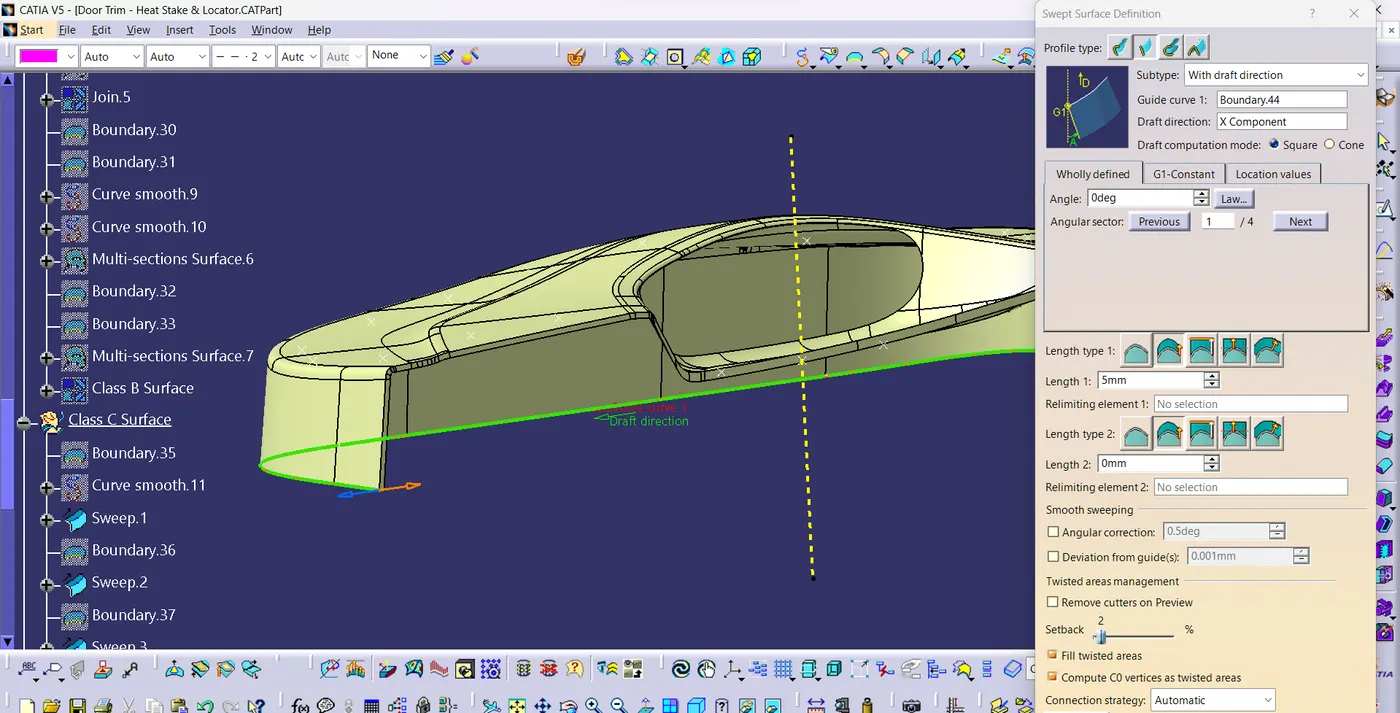
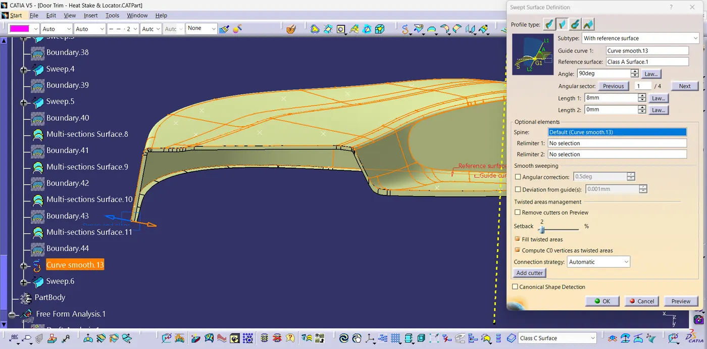
Step 4 : Create the closed surface and using this surface create the solid part body.
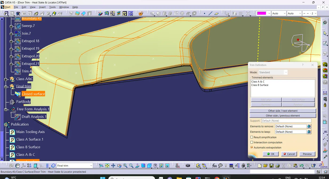
- Trim the Class A & C surface with Class B to get a closed surface.
- Using the 'Close surface' Command convert the closed surface to solid body.
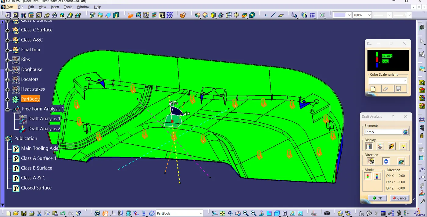
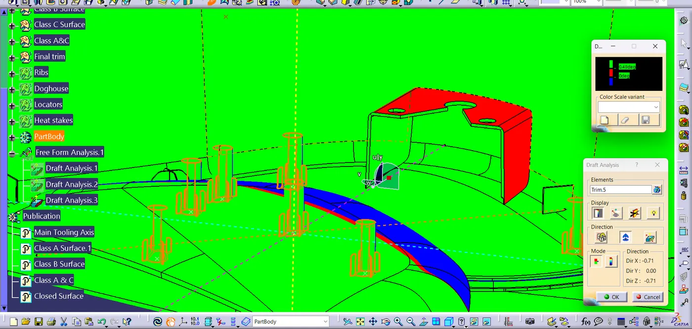
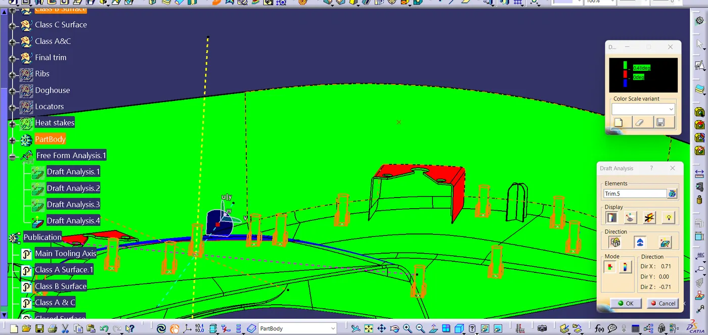
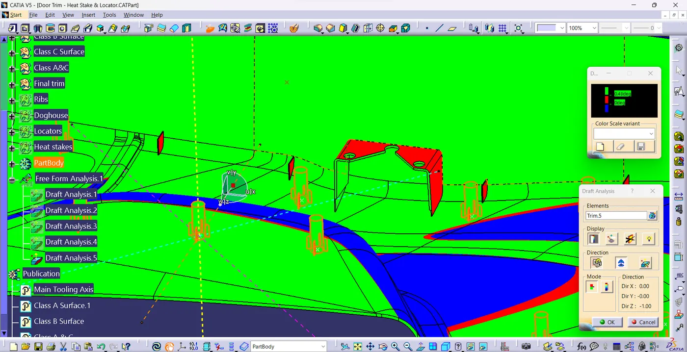
- Carry out the draft analysis
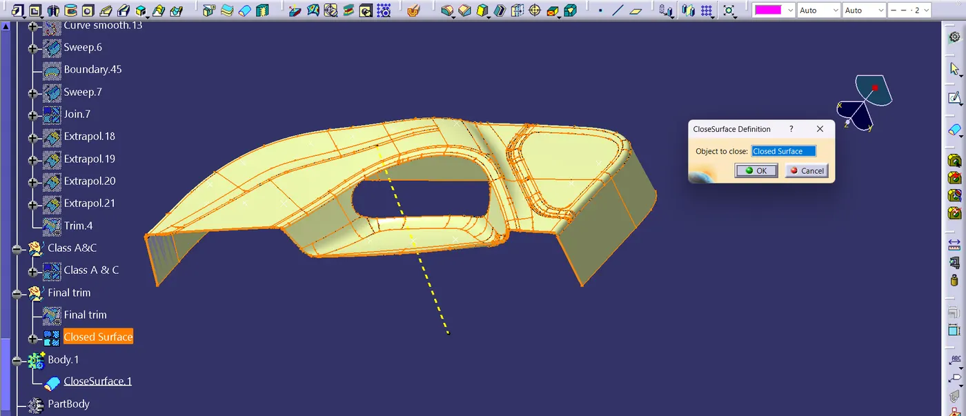
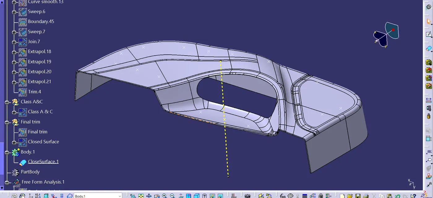
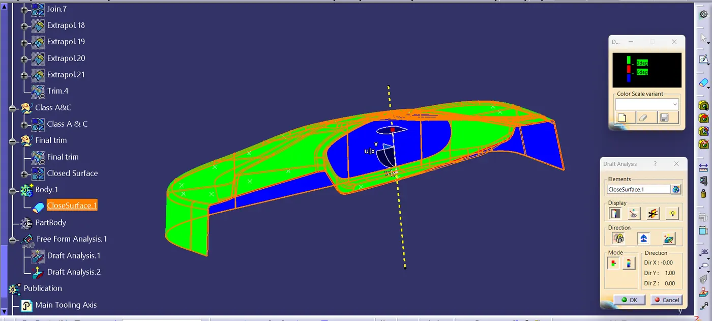
Class is clearing the draft of 3 degree very well
Step 5 : Creating Ribs
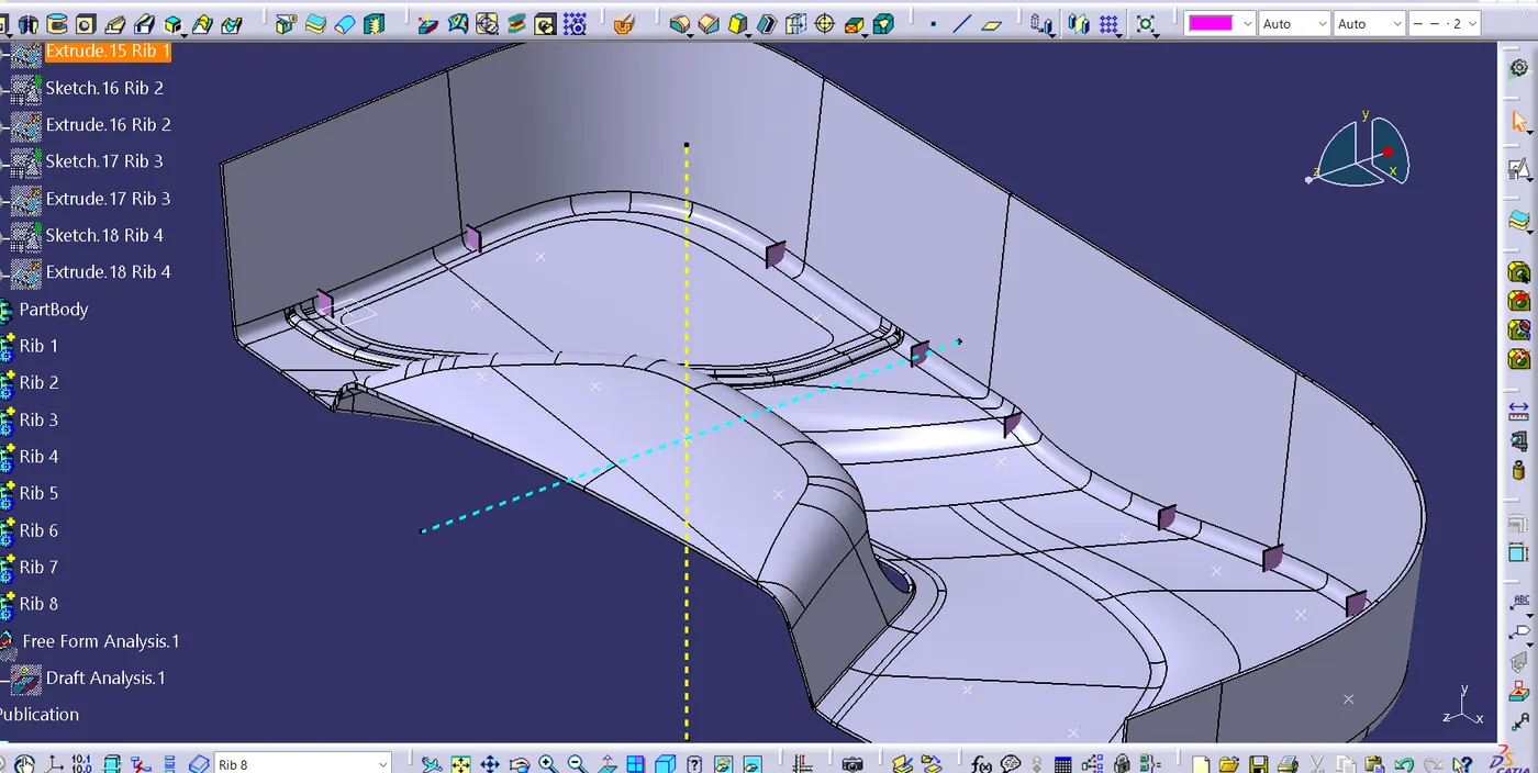
- Insert a geometrical set for creating Rib.
- Insert plane to make sketch for rib.
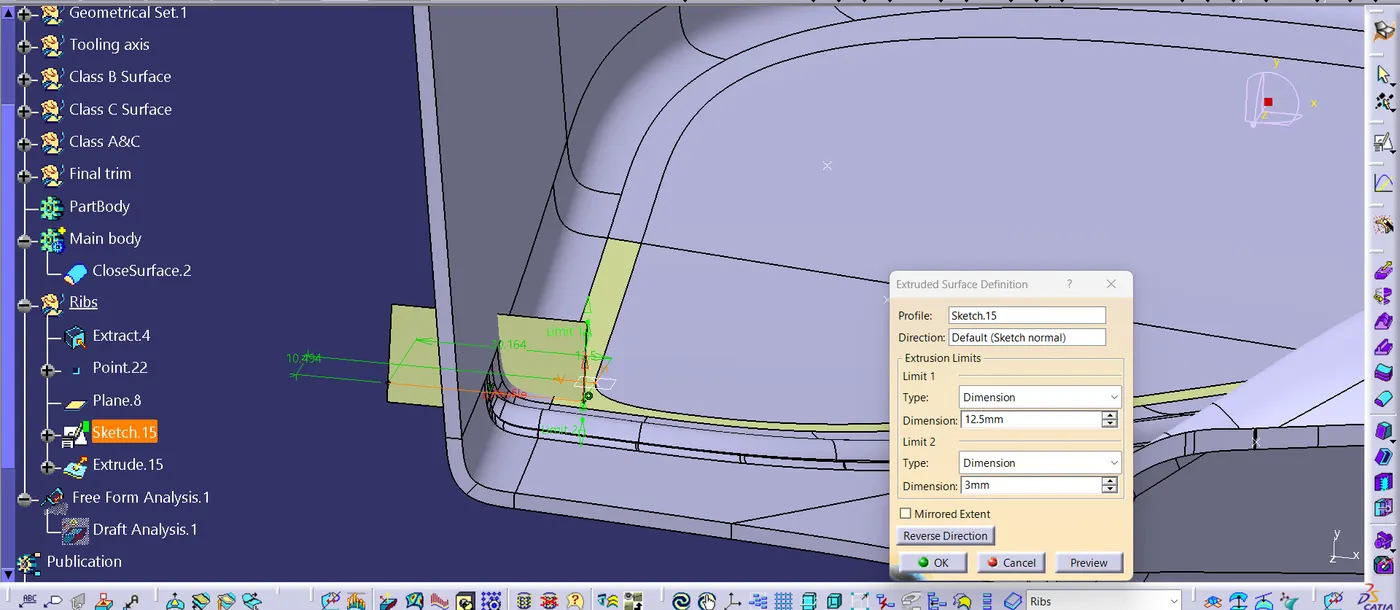
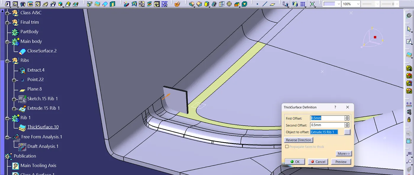
- Extrude the sketch and then give thickness using thicken command
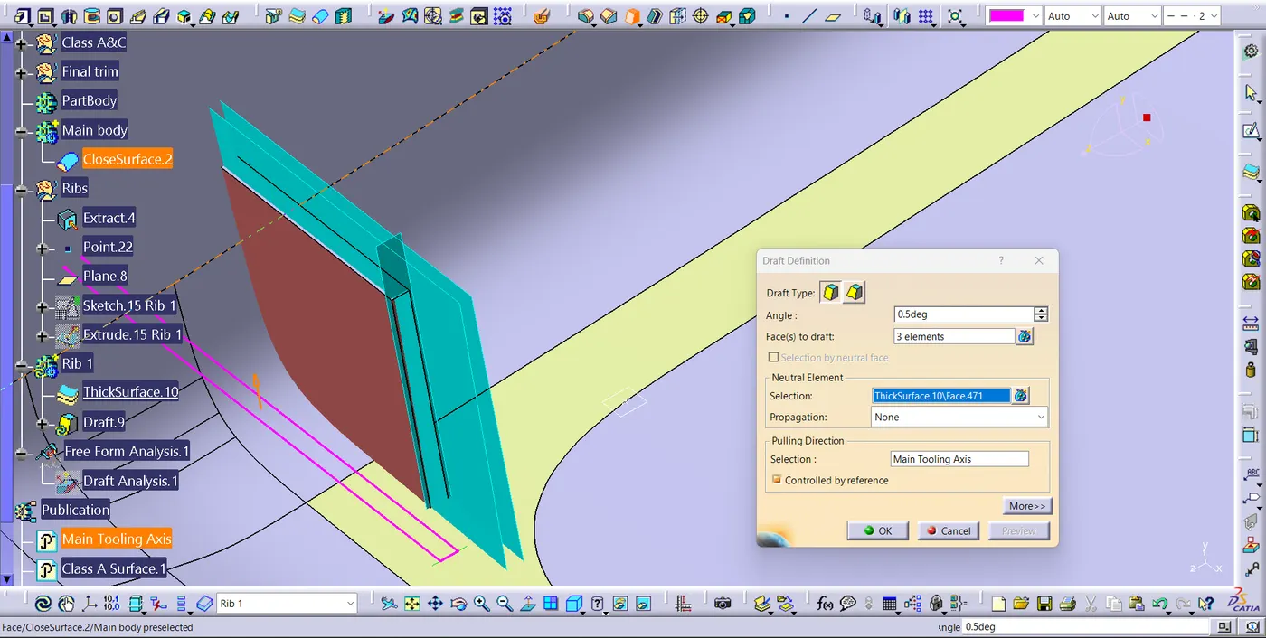
- Then provide draft of 0.5 degree with the main tooling axis.
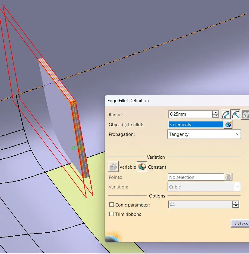
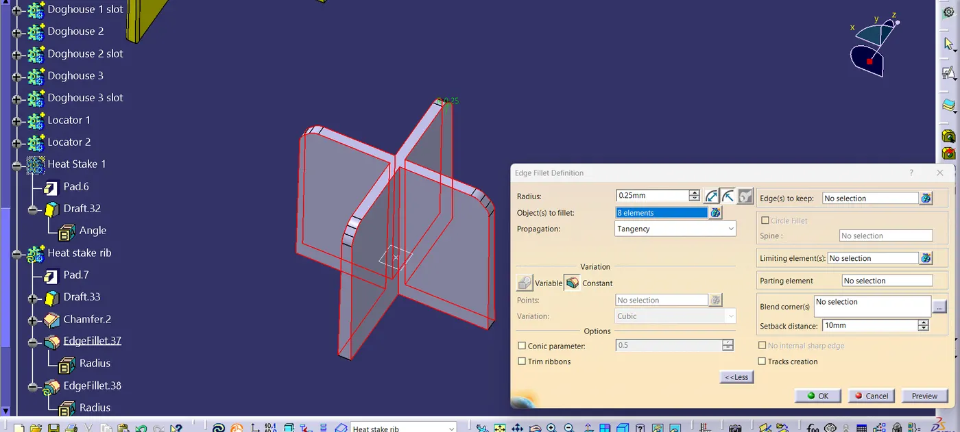
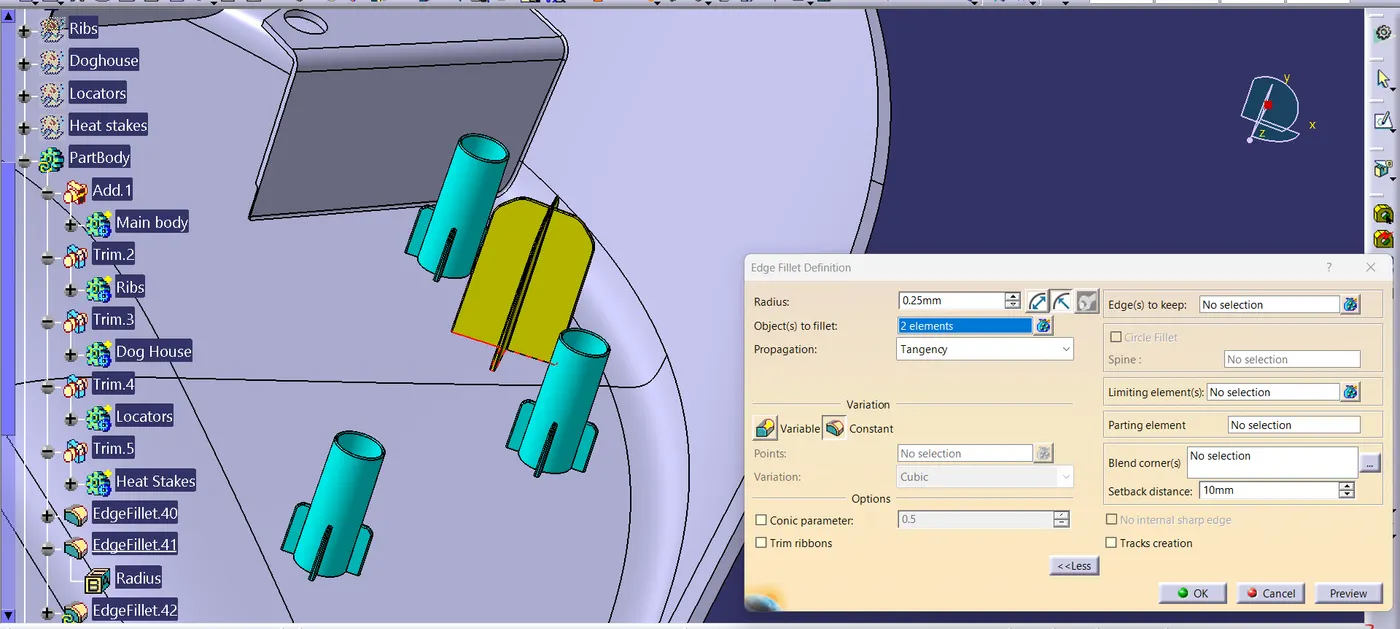
- Give edge fillet of 0.25 mm to the rib.
Rib design calculations fot the body thickness of 2.5 mm as follows
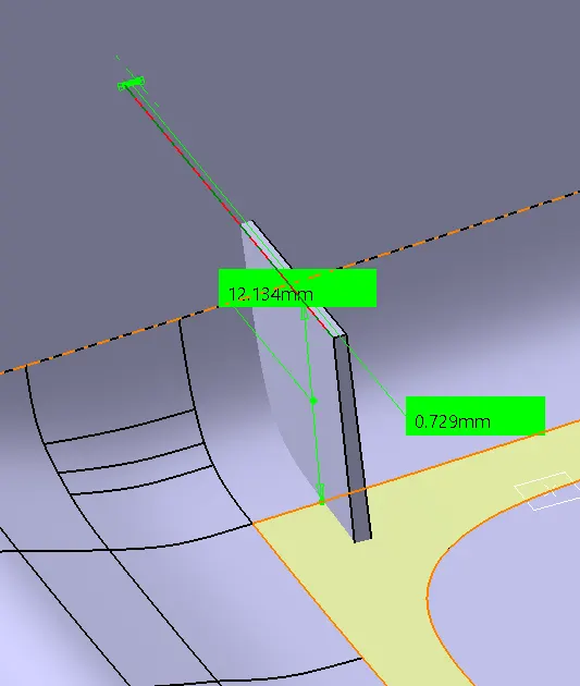
- Rib Length = 5×2.5mm = 12.5mm max
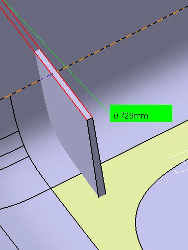
- Rib Thickness = 0.4×2.5mm = 1.00mm
- Rib Fillet Radius= 0.25mm
- Rib Draft = 0.5deg
- Rib Thick at Tip = 0.75mm
- Rib root thickness - +- 30% of wall thickness
- Spacing(S) - >=3T for steel and >=2T is preferred
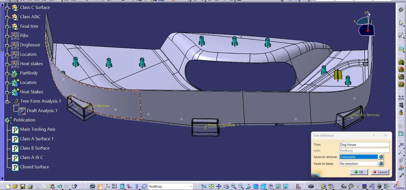
Step 6 : Creating Dog House
- Insert geometrical set for creating doghouse.
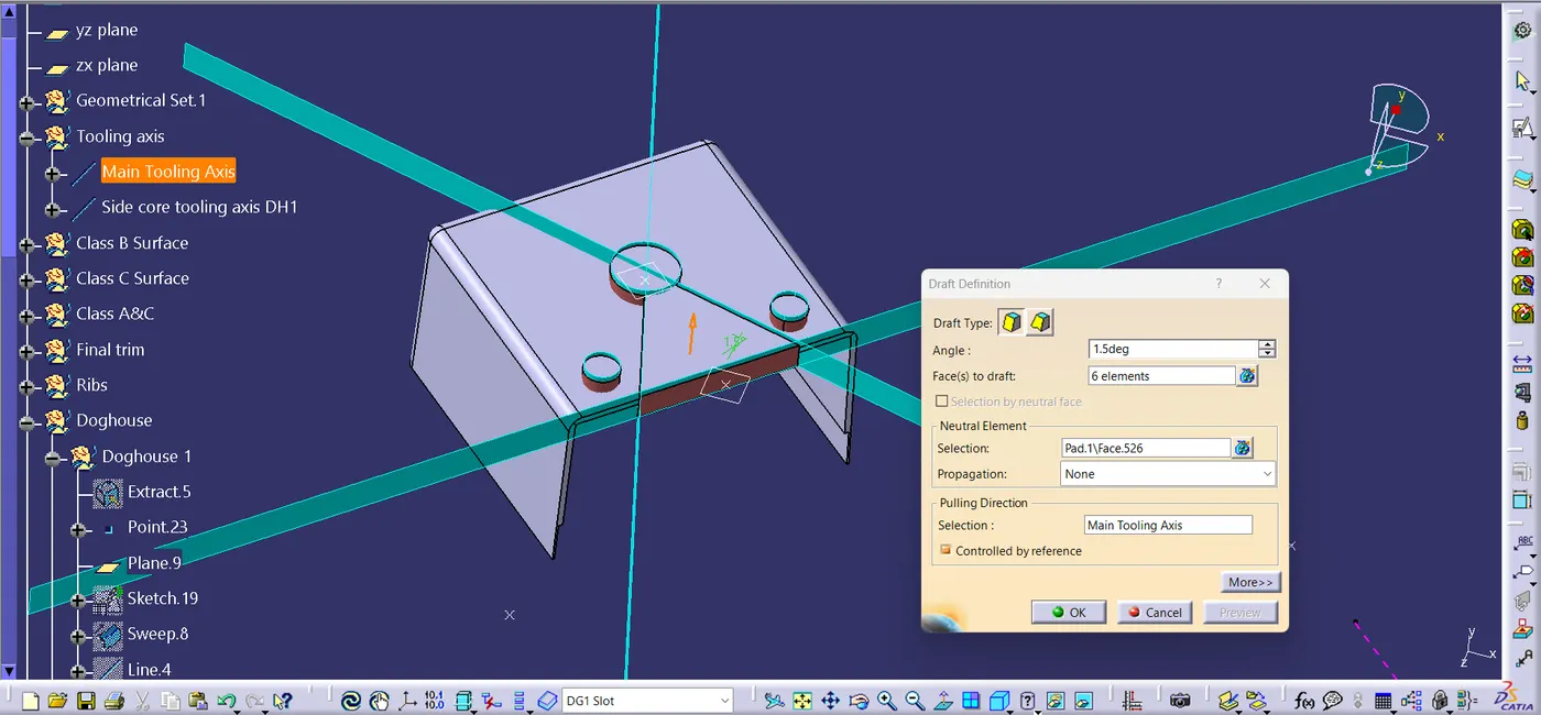
- Make a side core tooling axis for providing draft.
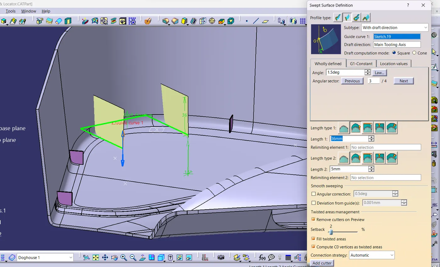
- Extract the surface and add a point and plane on it to make sketch which will be extruded and thickned.
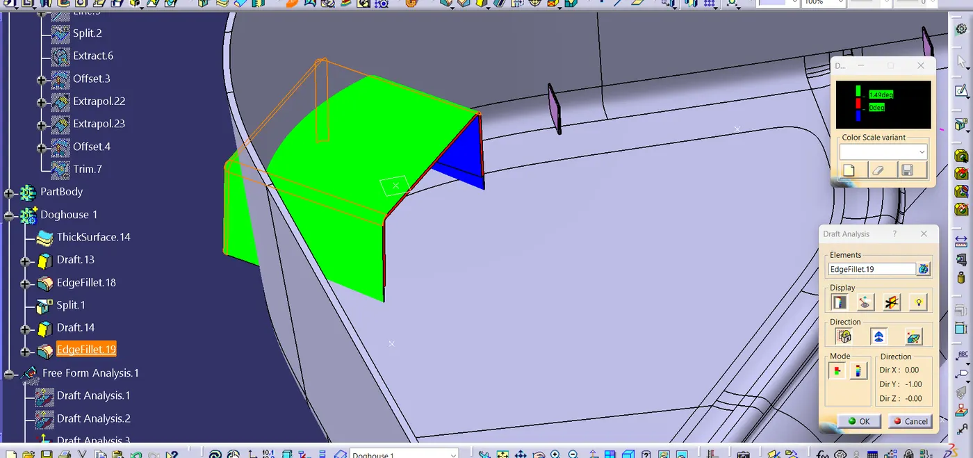
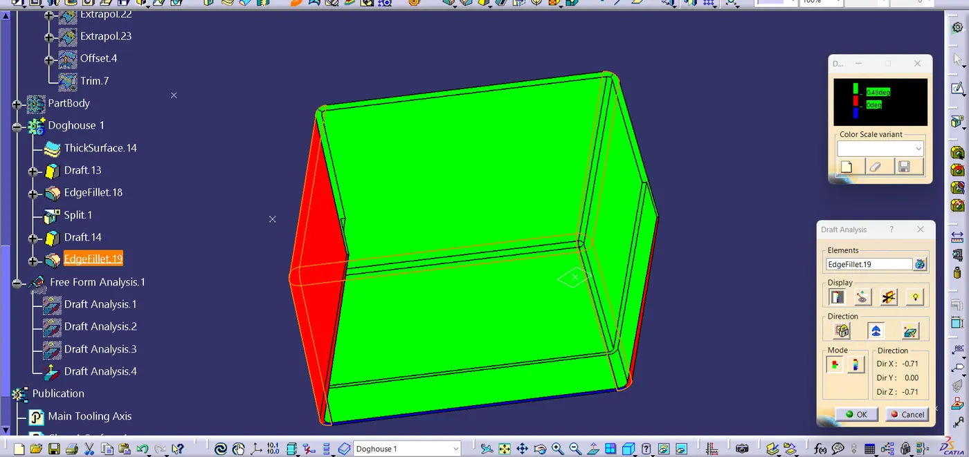
- Provide draft of 1.5 degree for the outer surface with main tooling axis and 0.5 degree for inside surface with side core tooling axis of the doghouse.
- Provide the edge fillets.
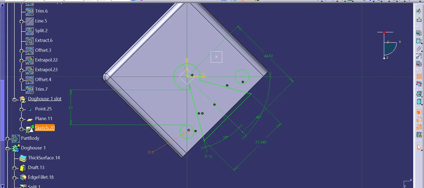
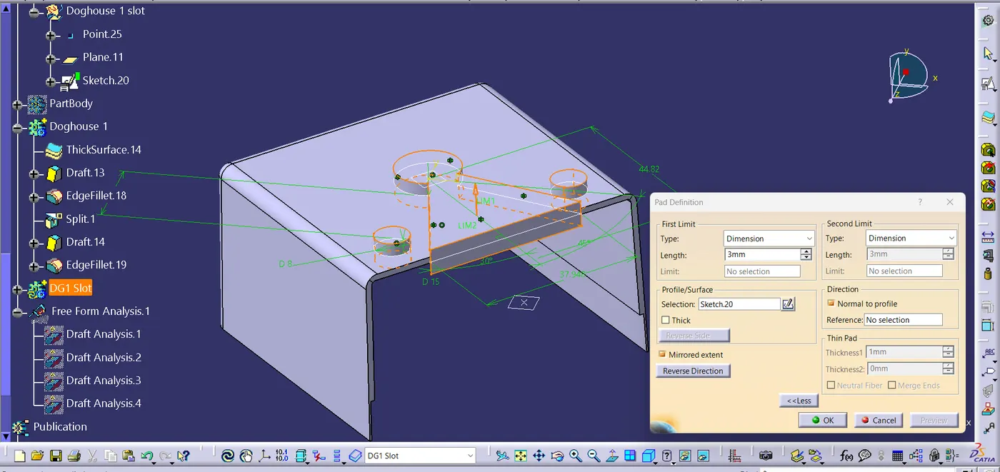
- Create the slot for push pin and screw/bolt by padding.
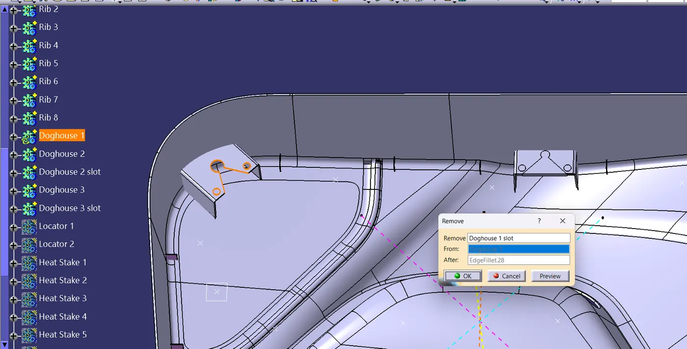
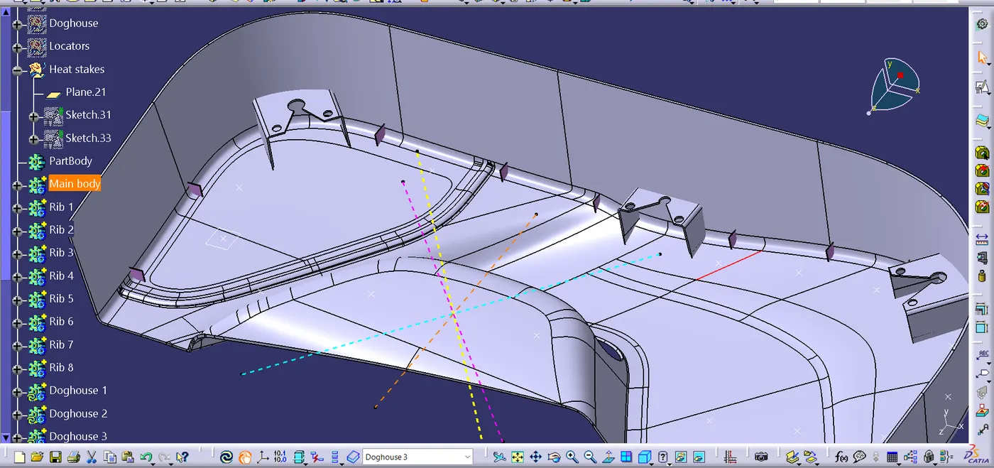
- Join the dog house using union trim to the main body and remove the slot.
Design Criterias:
- C thickness should be 40% of the main wall thickness T
- Minimum width of the dog house is 12 mm.
- Height of B should be 3-6 mm
- Minimum draft for the do house is 1.5 degree to tooling axis.
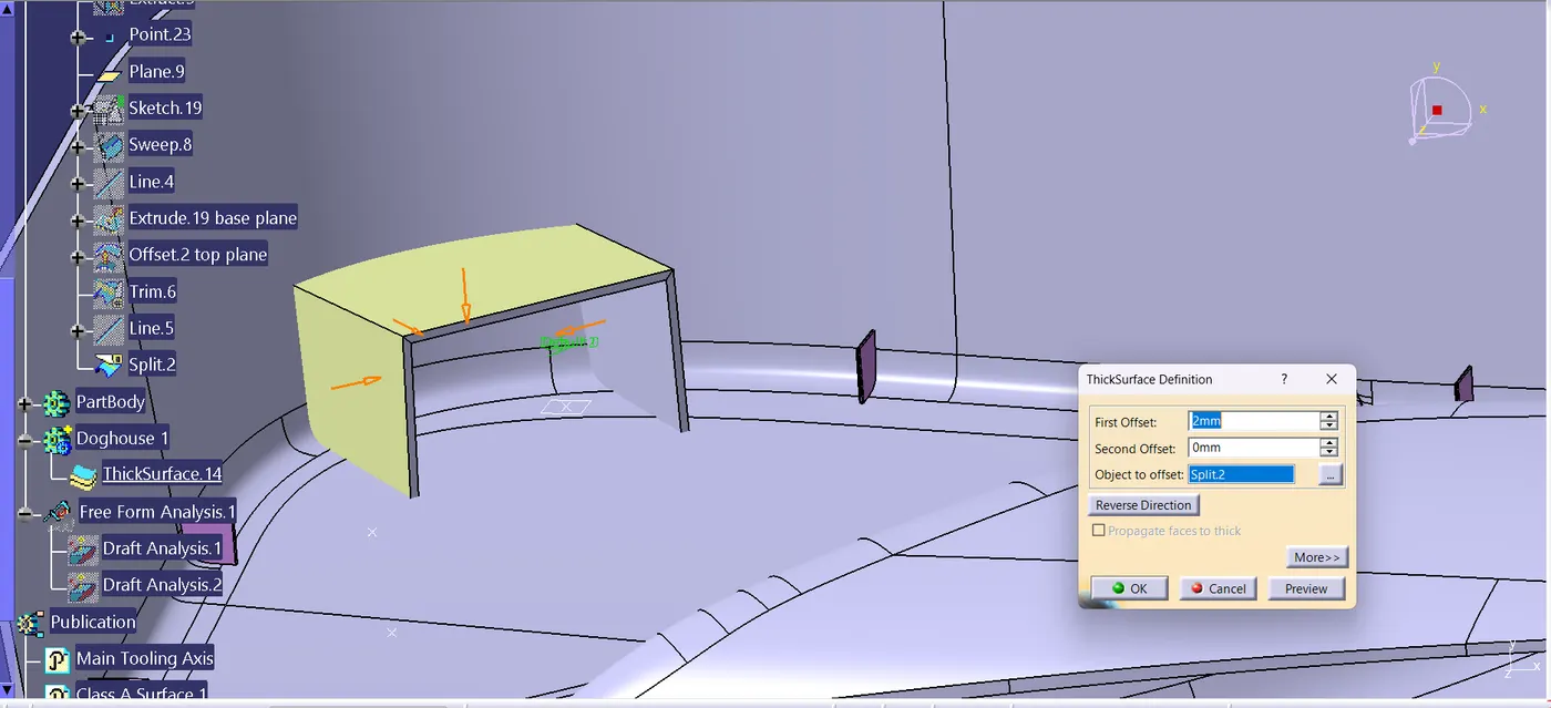
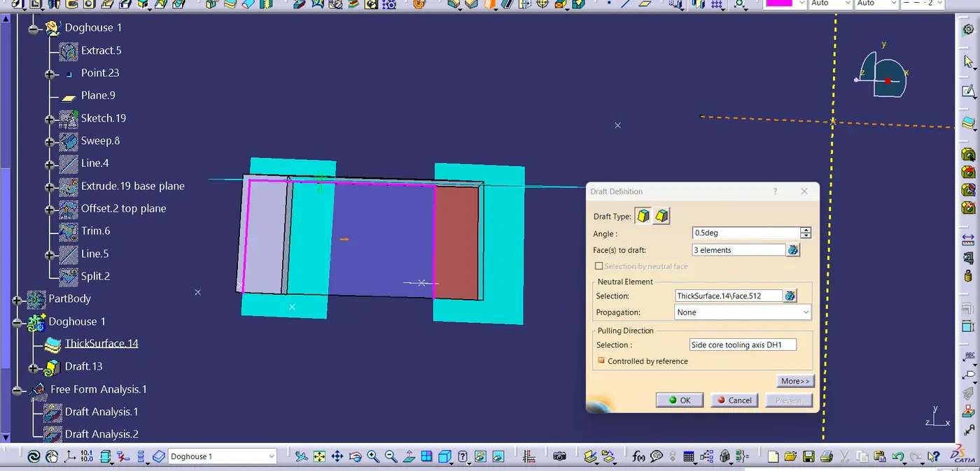
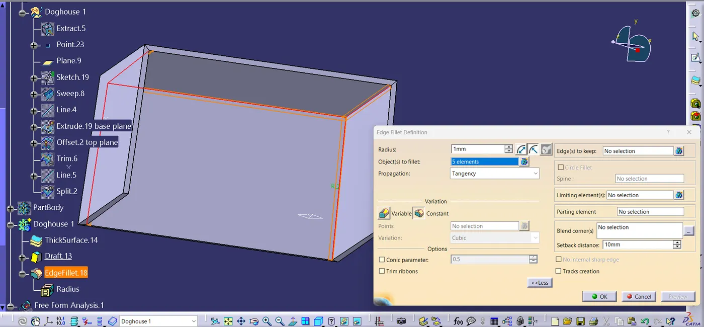
Thickness at C should be 40% of wall thickness = 0.4 * 2.5 mm
= 1 mm
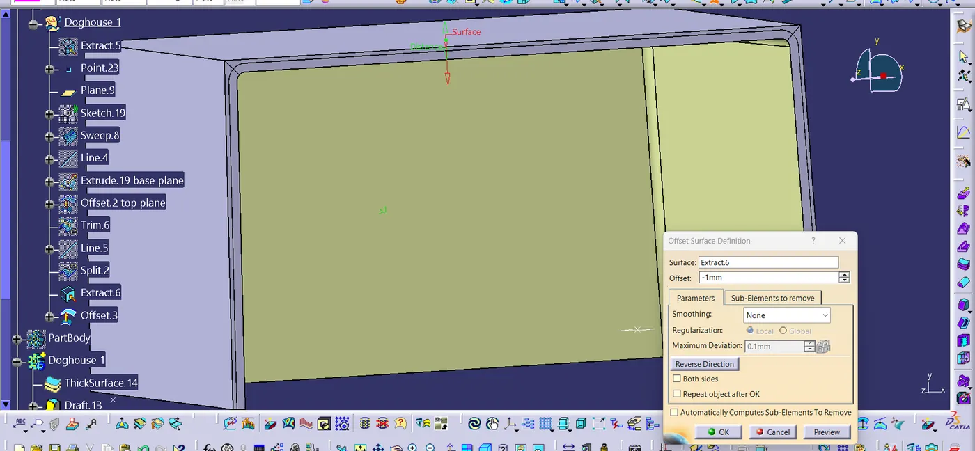
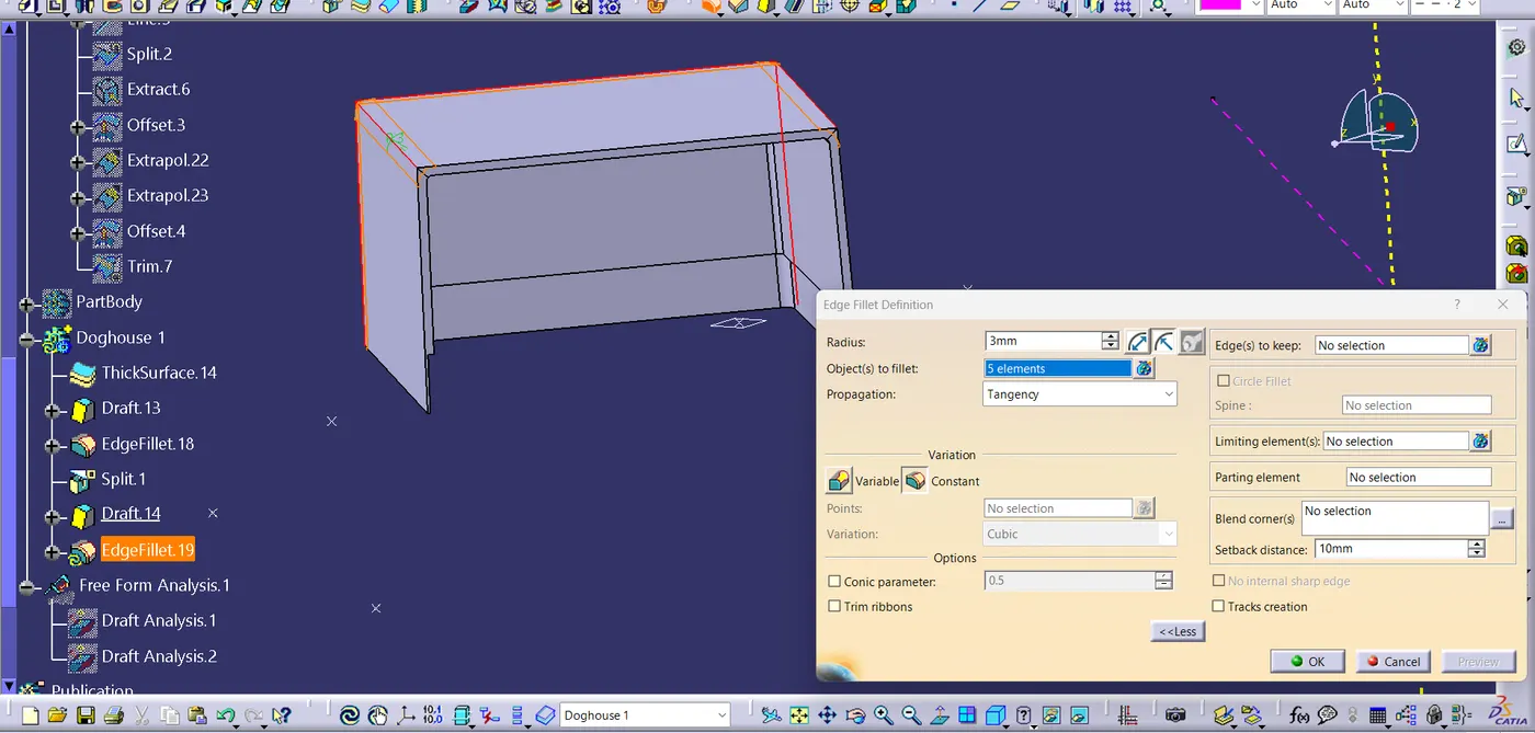
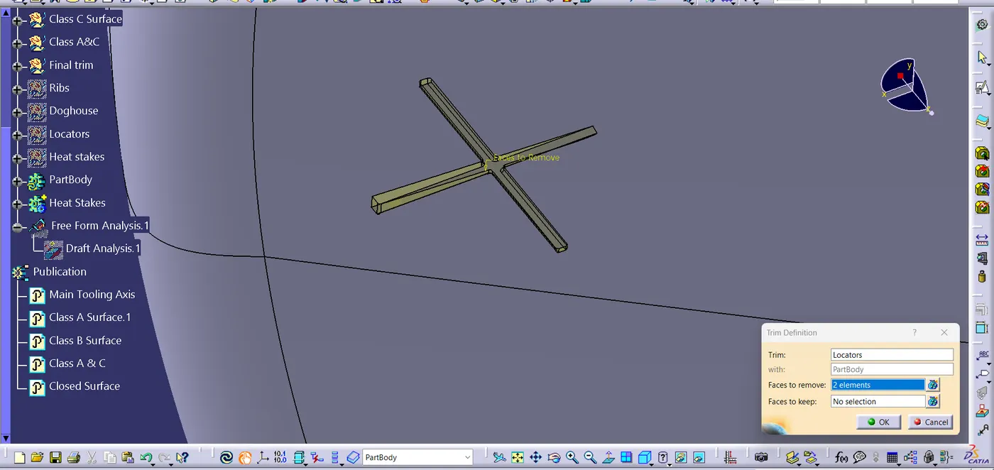
Step 7 : Creating locatores
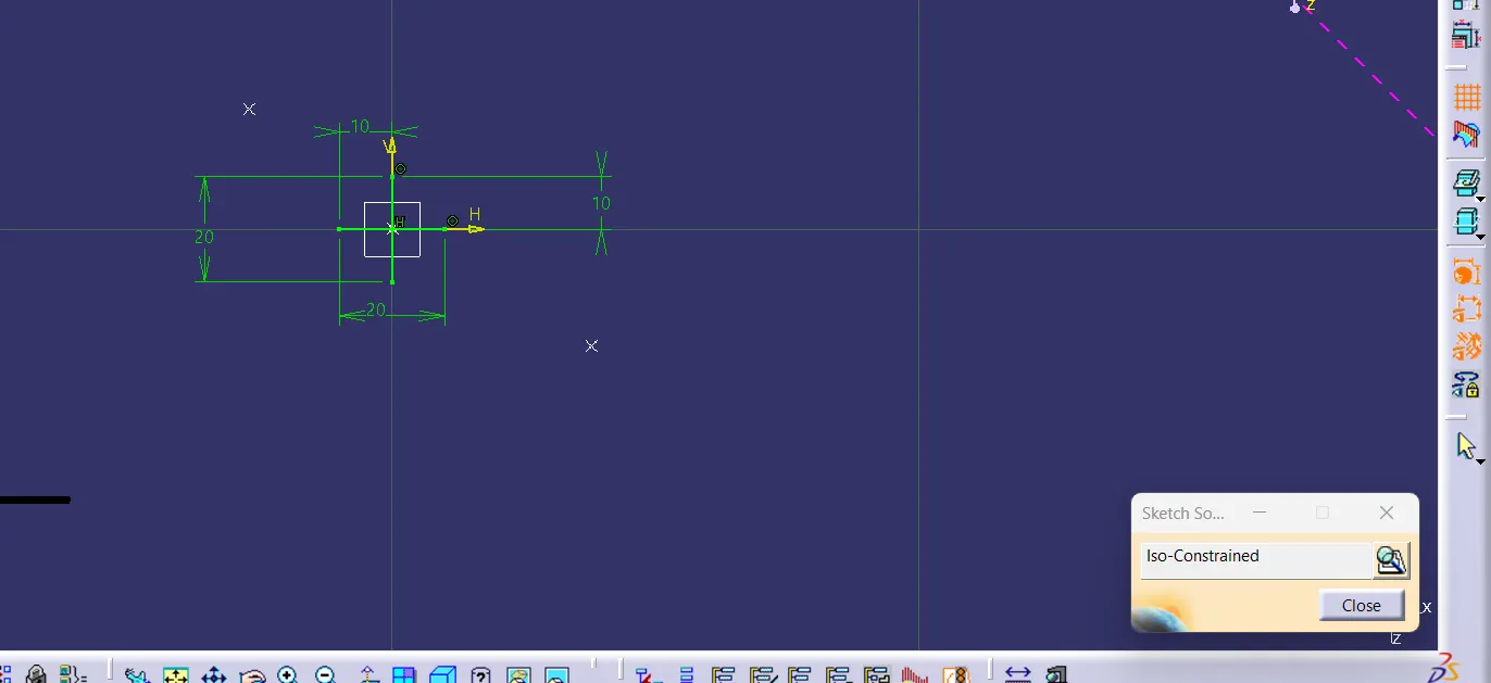
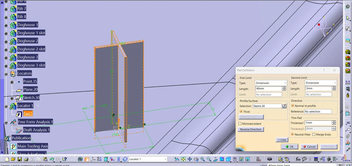
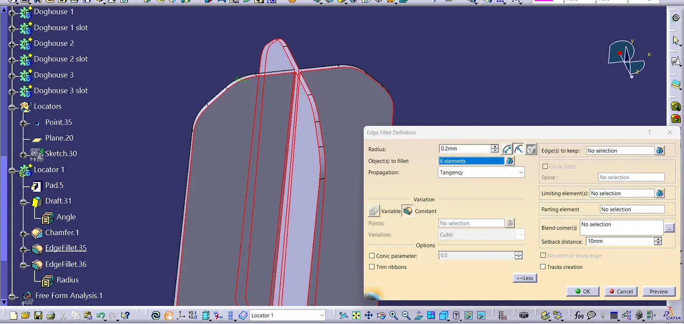
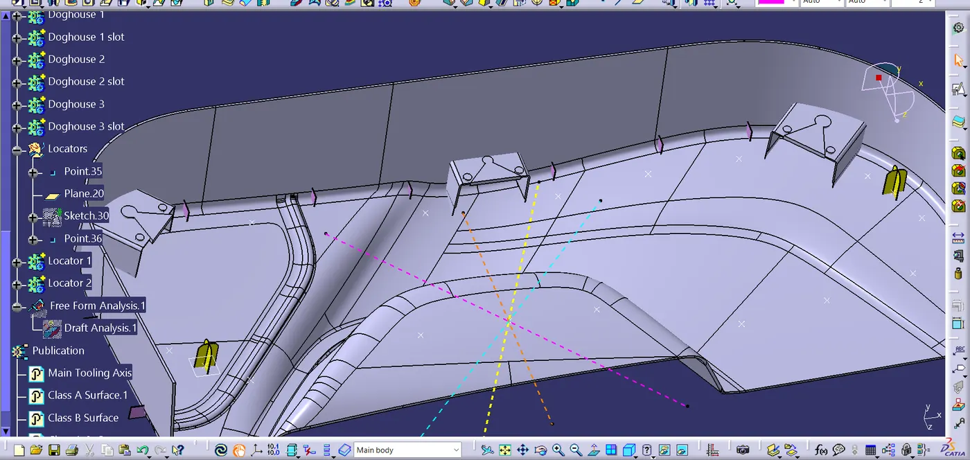
- Insert geometrical set for the locators,define the point and plane for sketch positioning and sketch the locator.
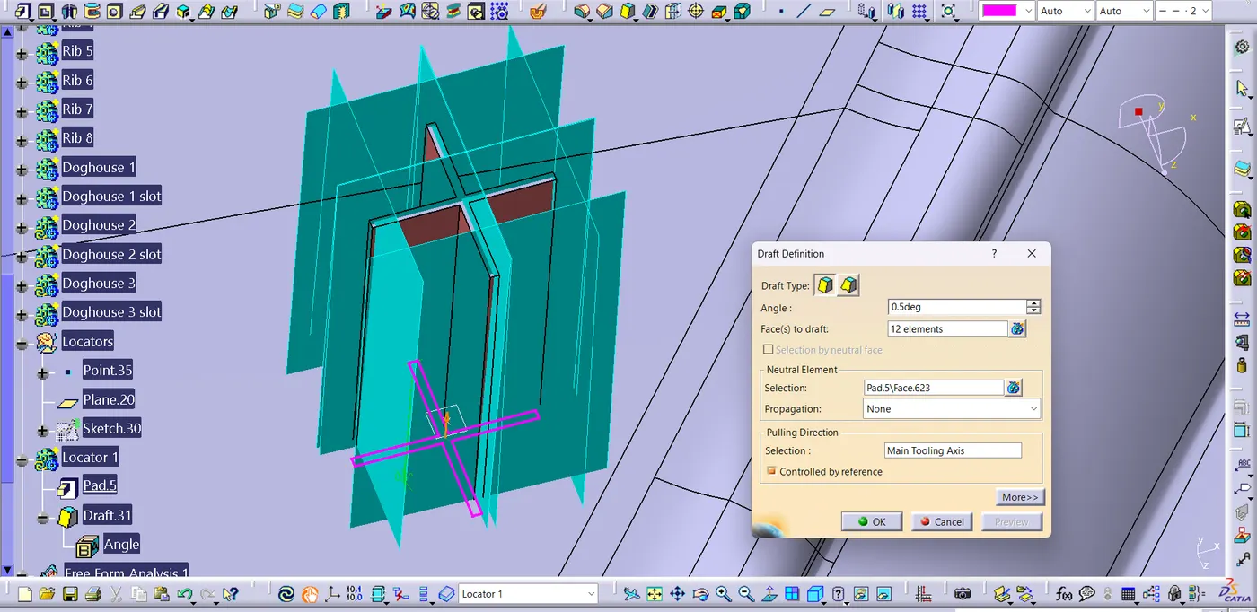
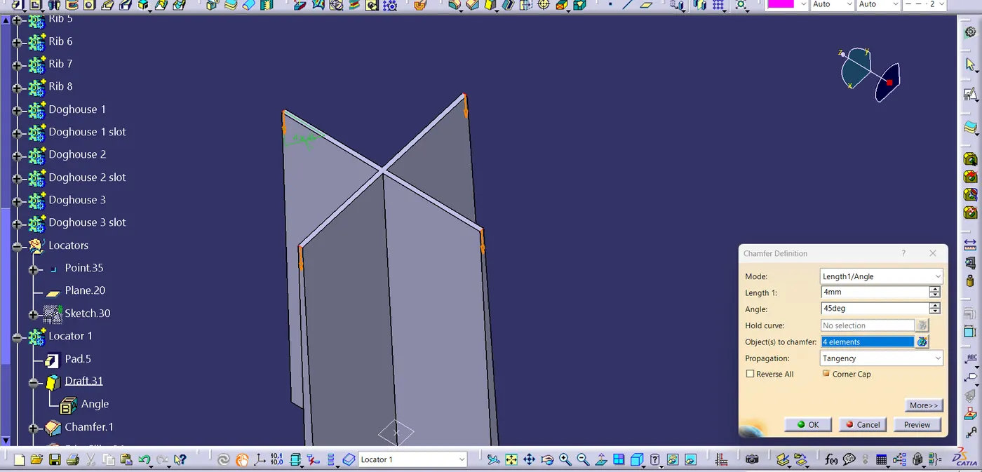
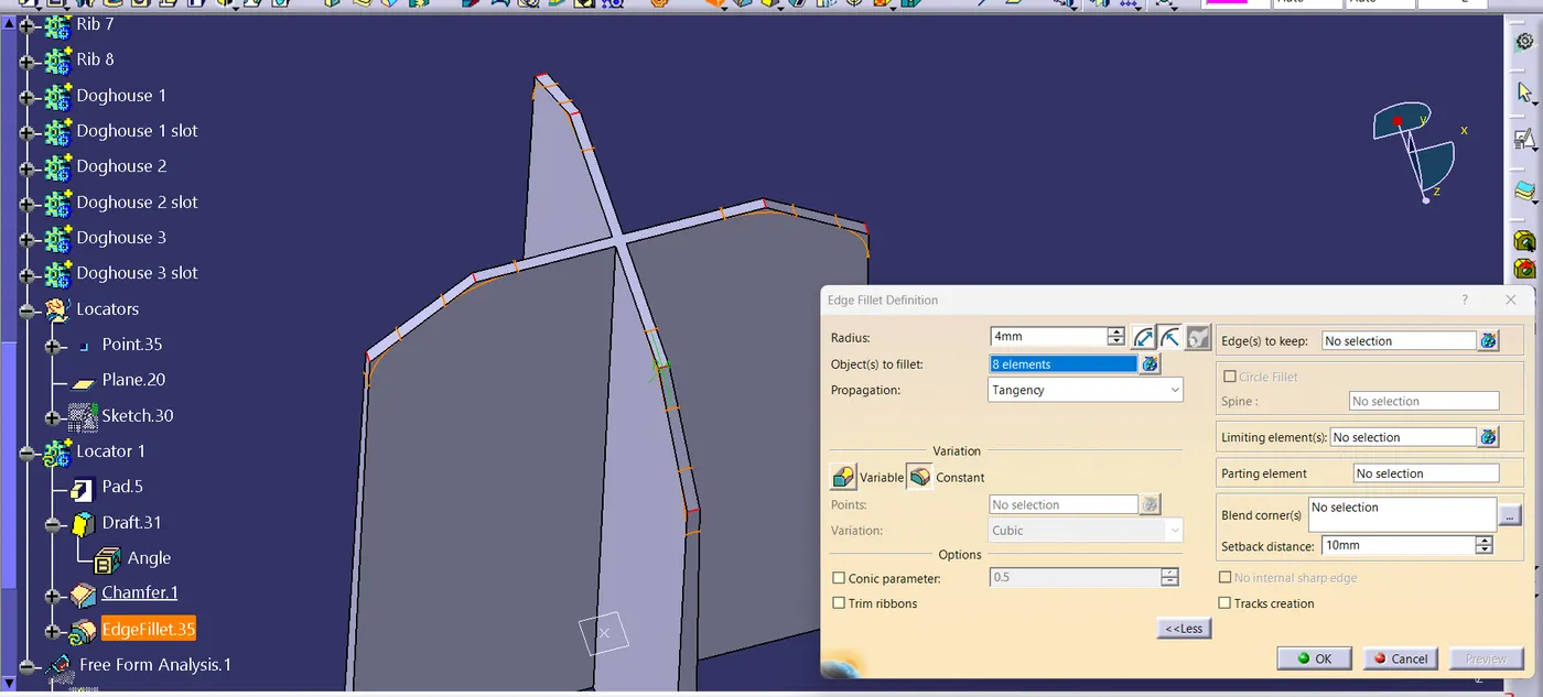
- Using pad command pad the sketch and then give draft , chamfer and fillet.
- Thickness of locator = 2.5 * 0.4 = 1 mm
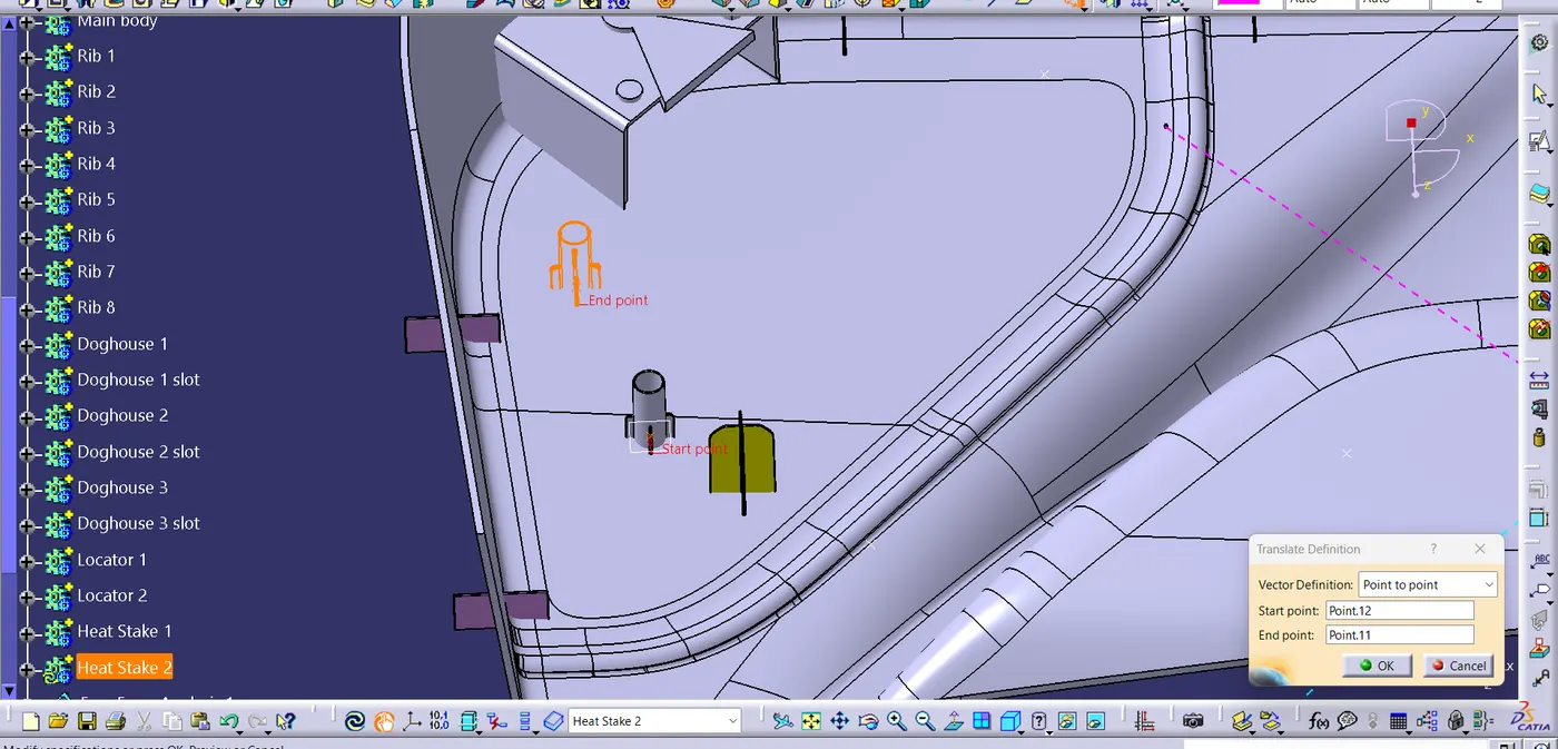
- After creating one locator move to next location using copy - paste and translate commands.
- Also make sure the locators are of same height.
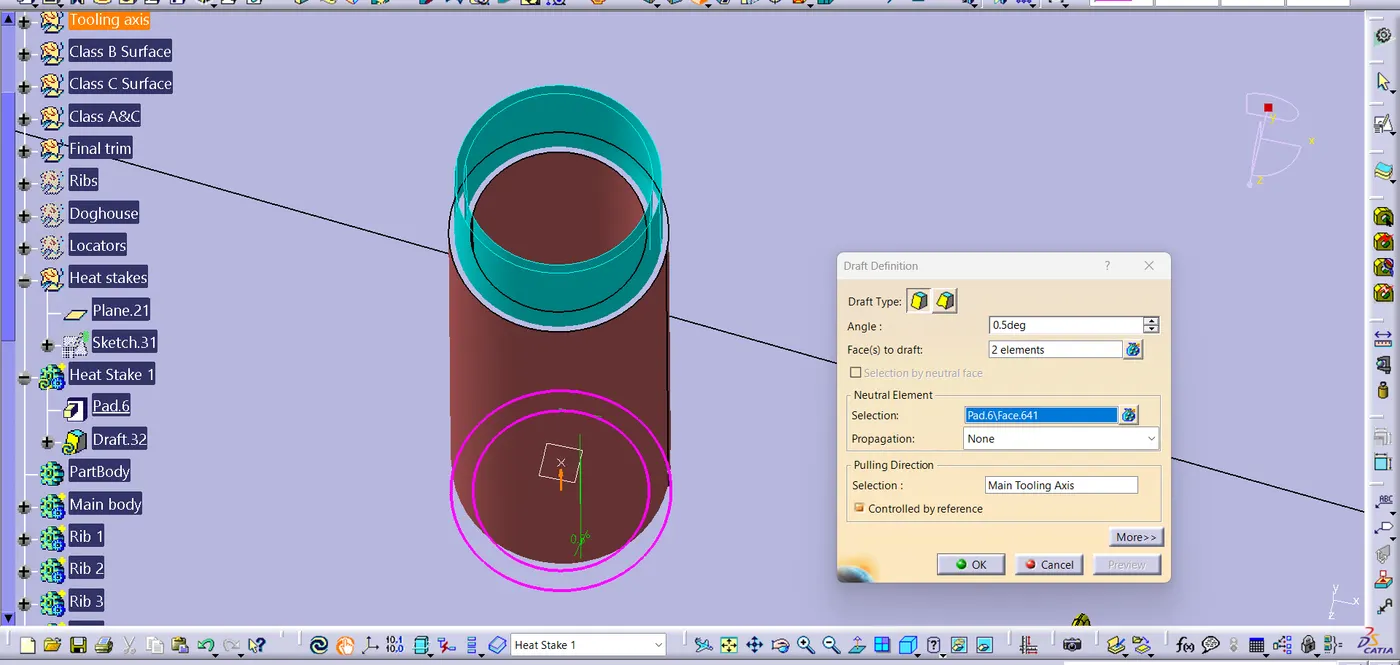
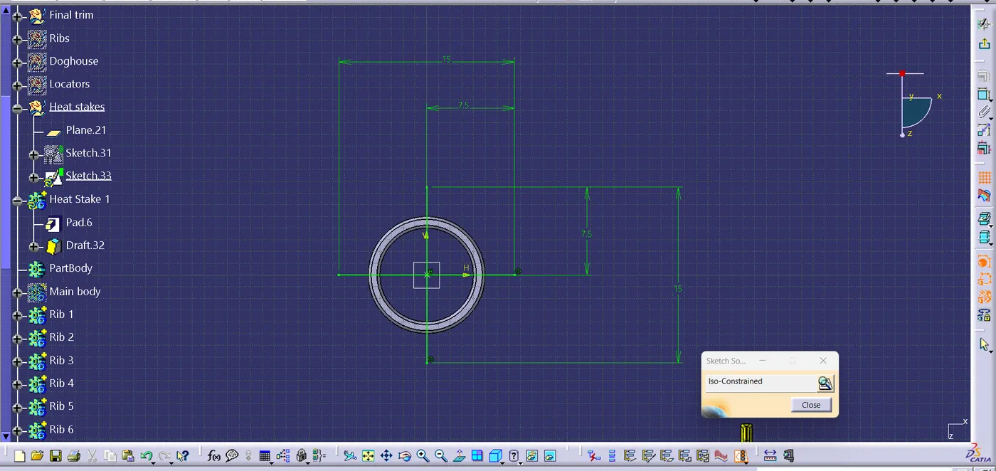
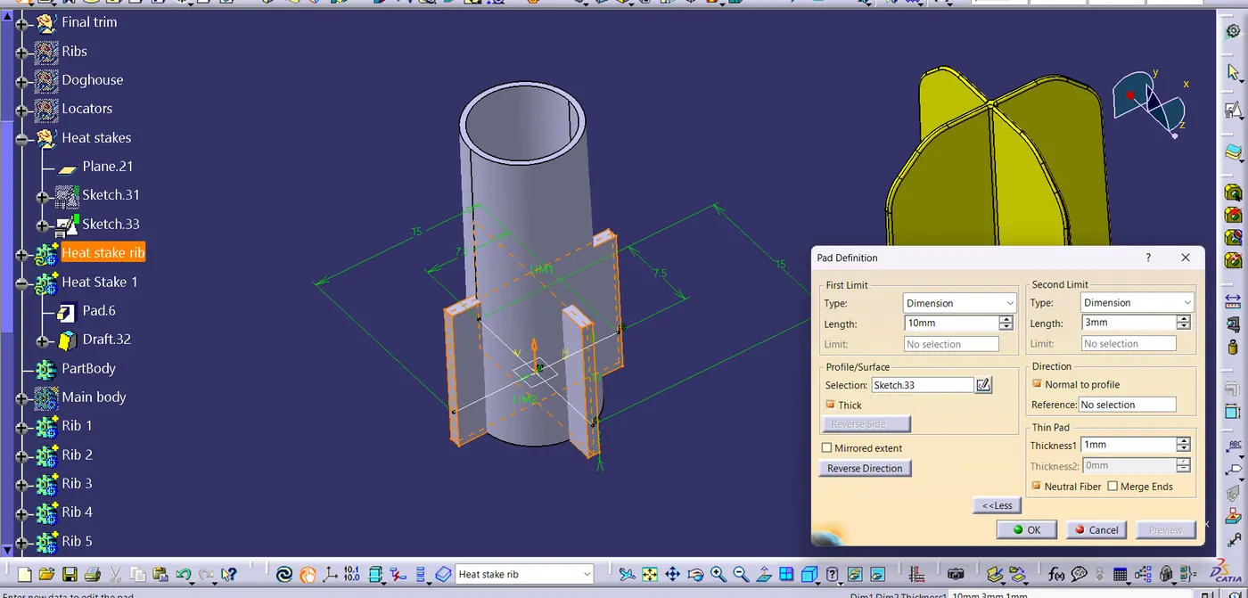
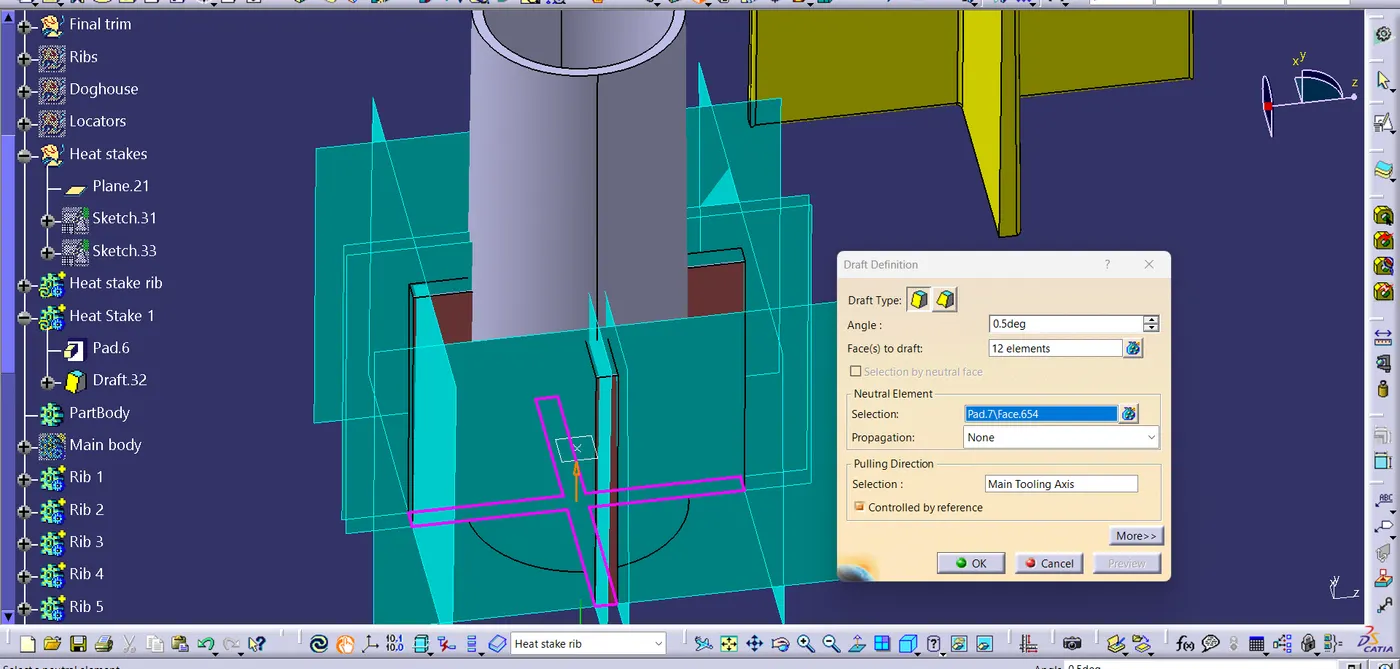
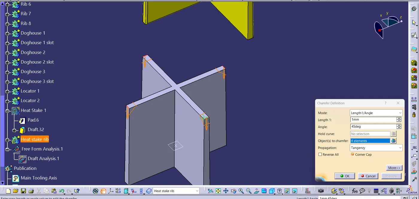
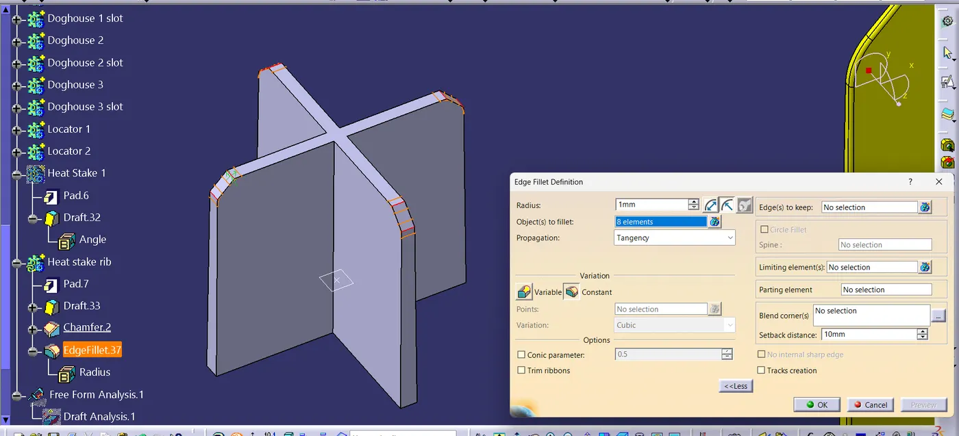
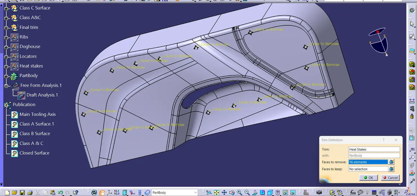
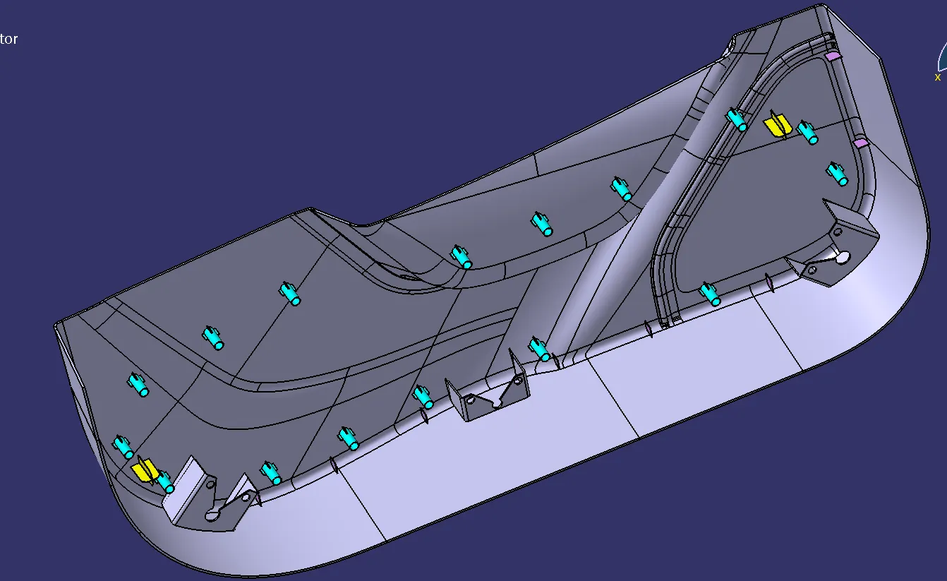
Step 8 : Creating heat stakes with rib
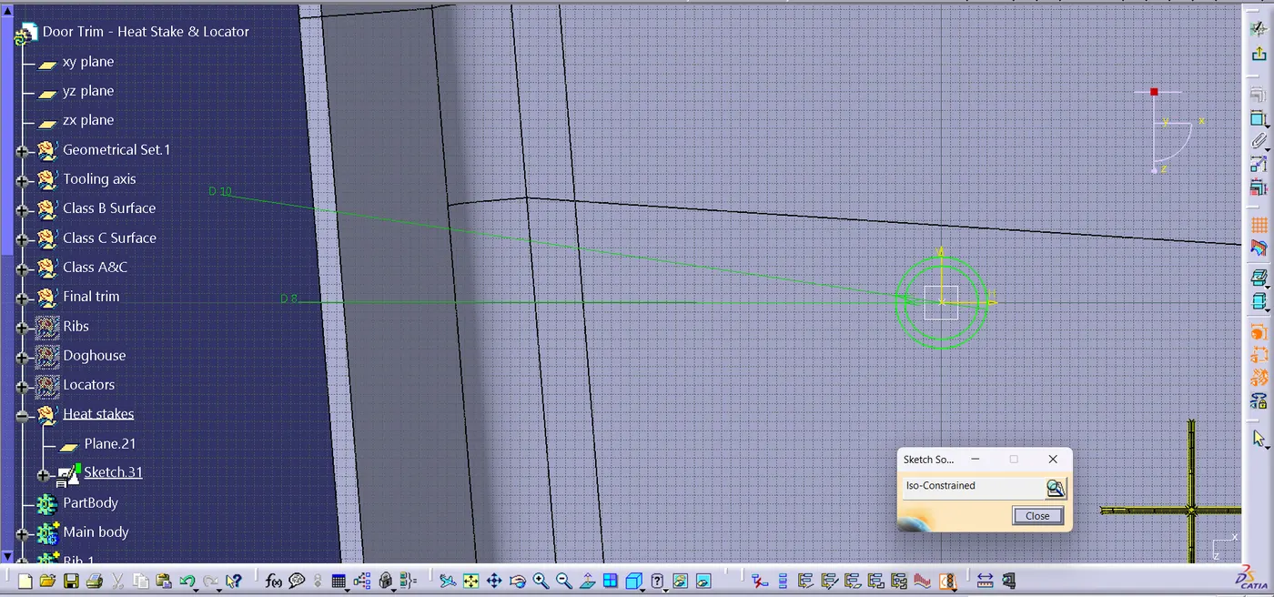
- Insert a geometrical set for creating the sketch, make the sketch for the heat setakes.
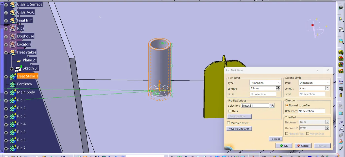
- Extrude the sketch using pad command and give draft of 0.5 degree.
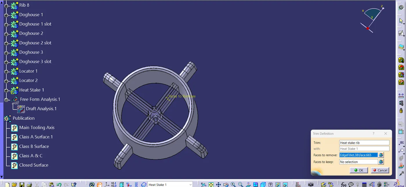
- Make the sketch for rib and pad it and gibe fillet and chamfer. Union trim it with the heat stake.
- Copy and translate the heat stake made to requried locations.
- Wall thickness of heat stake = 2.5 * 0.4 = 1 mm
- The height of heat stake should be less than the locators.
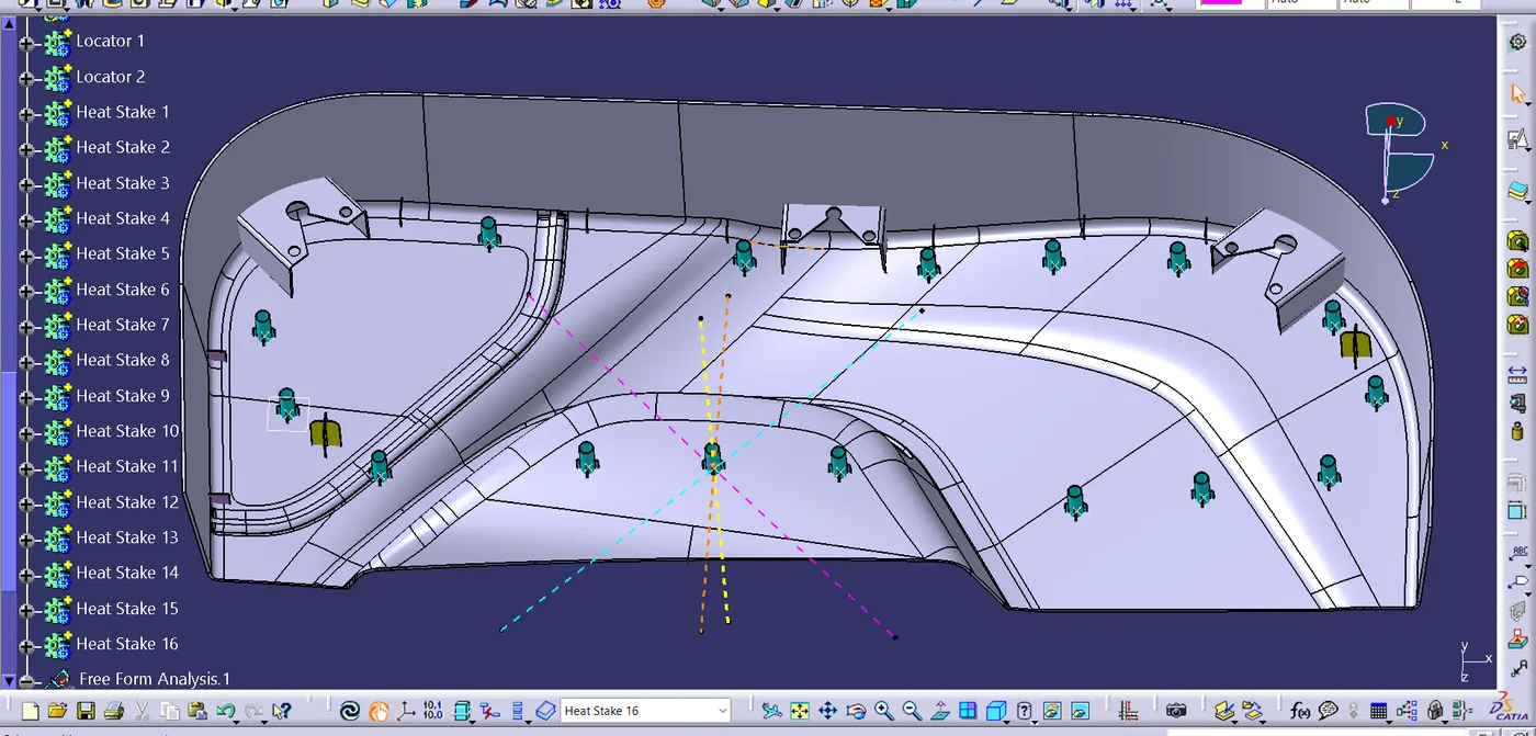
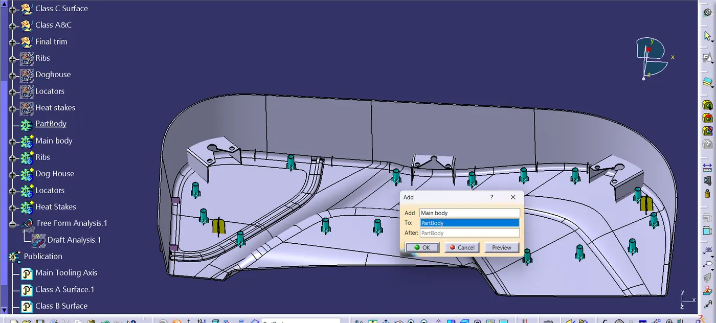
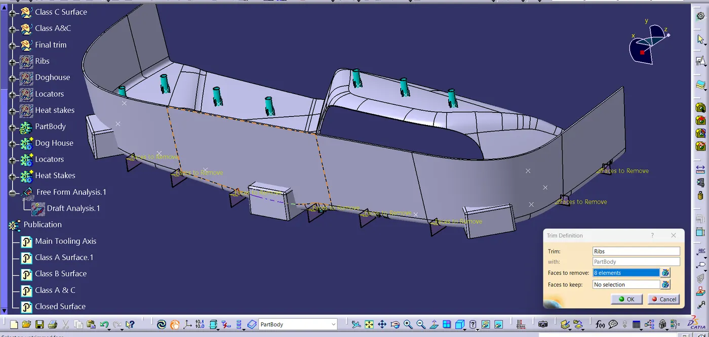
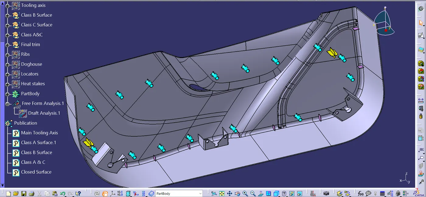
Step 9 : Arranging and Assembling all the parts and combining them with the part body and do draft analysis.
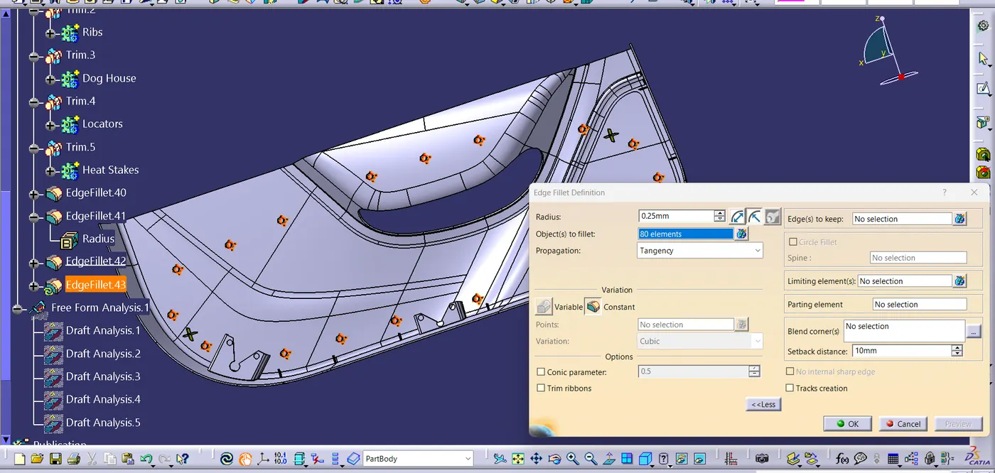
- Finally give fillet to all necessery areas.
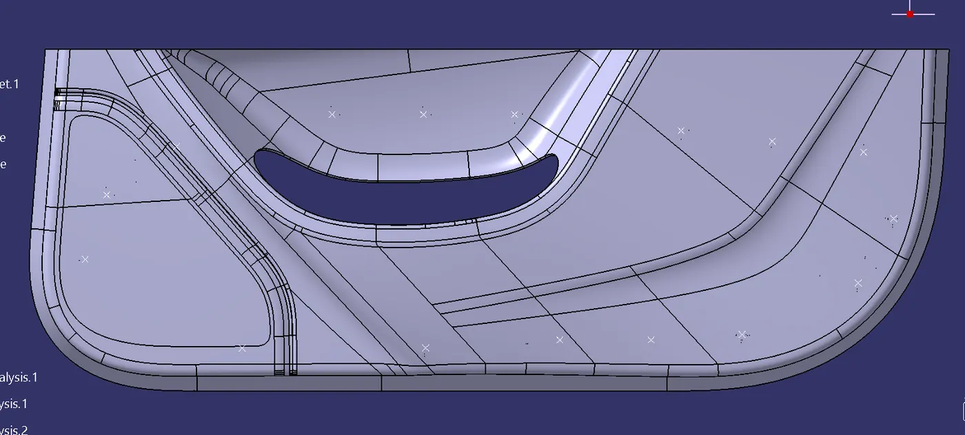
Front View
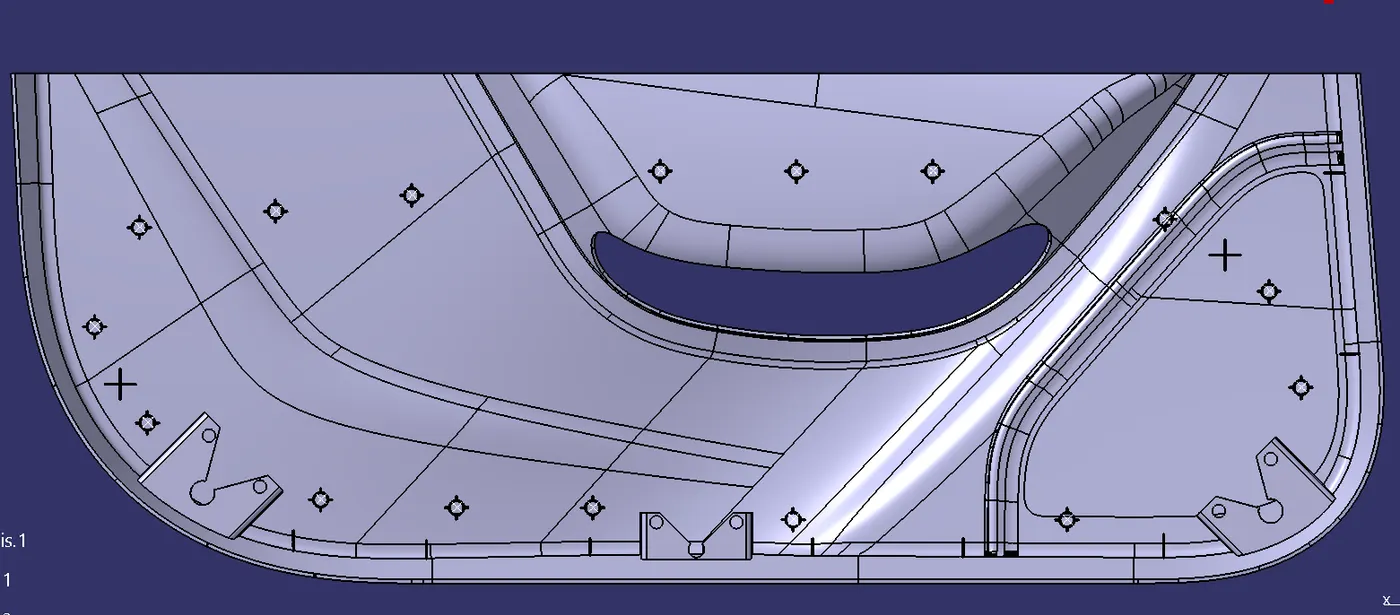
Back Side View
Top View
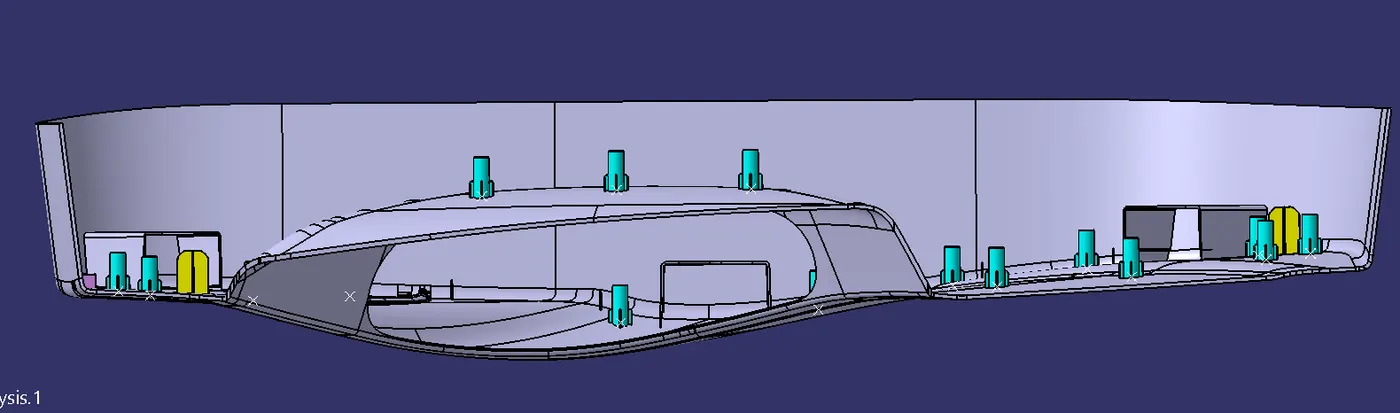
Bottom View
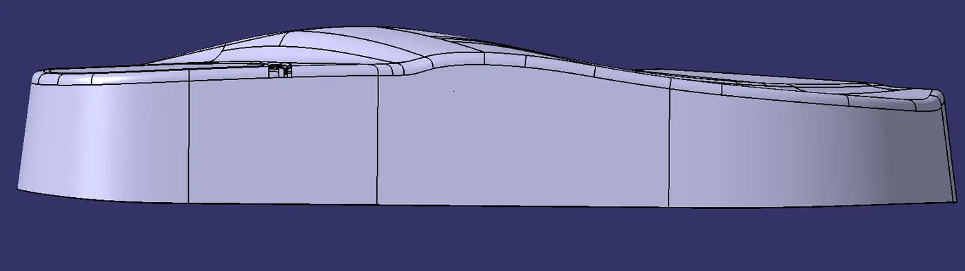
Side View
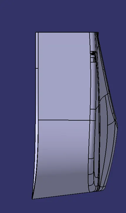
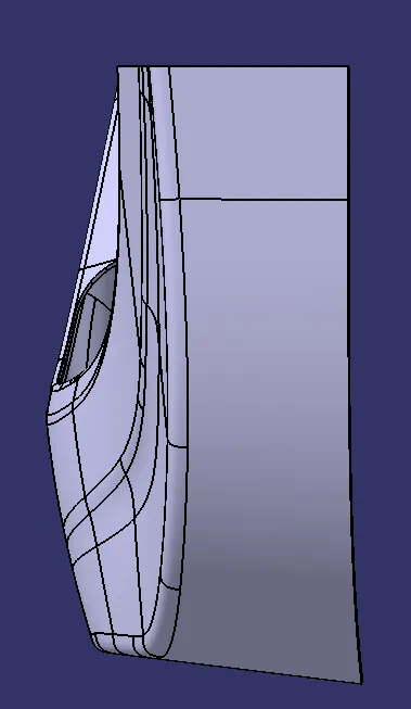
Isometric View
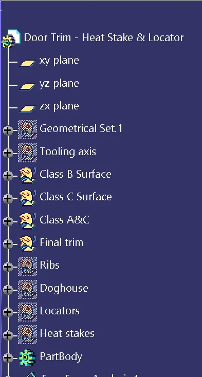
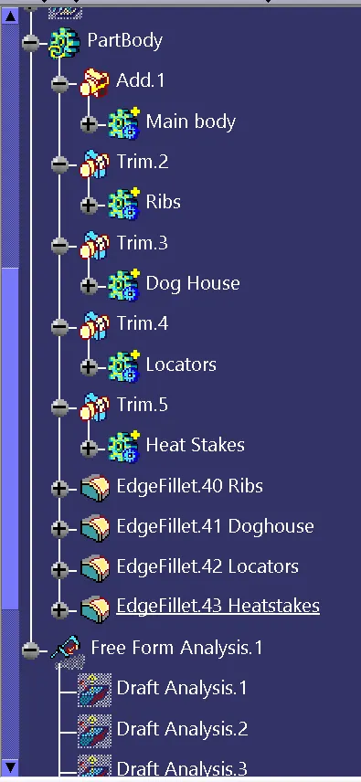
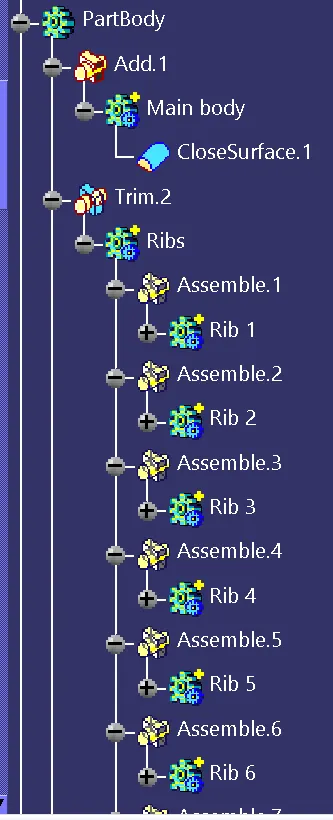
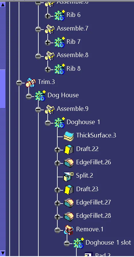
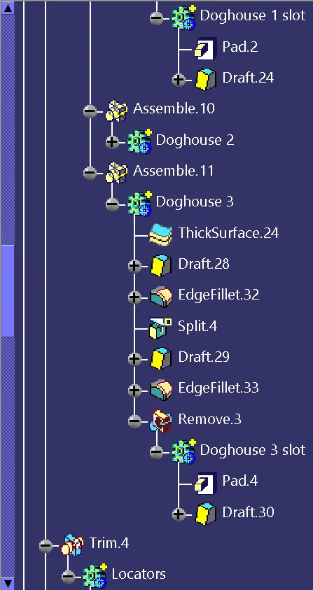
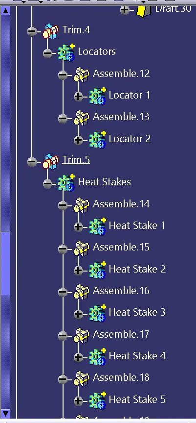
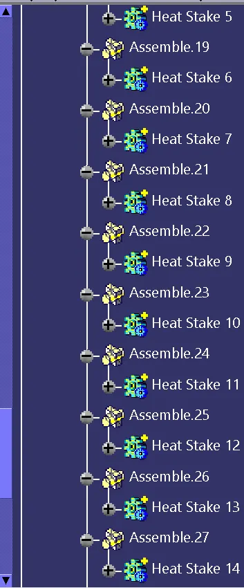
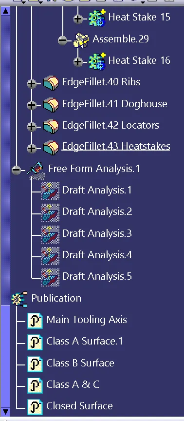
Tree Structure
CONCLUSION
- Created the Door Trim Lower Plastic component through the given Class-A surface.
- Created the Heat Stakes, the locators, ribs and doghouse considering the design rules