Week 7 Challenge - Assembly Workbench
AIM
- To create 2 assemblies from 2D diagrams of the components by creating the individual part files and then create a complete assembly of those part files in the assembly workbench.
- To create 2D drawing after completing the assembly
THEORY
Model 1 - Quick Return Mechanism
The quick return mechanism converts circular motion into non-uniform linear motion, enabling machines like shapers and slotting machines to achieve a faster return stroke than the forward stroke. It reduces cycle time and increases productivity by maximizing productive cutting or shaping time. Typically using linkages, gears, and cams, the crankshaft-driven mechanism swiftly moves the connecting rod during the return stroke. While once widely used in metalworking, advancements like CNC machines have partly supplanted it due to enhanced control and precision. Nevertheless, the quick return mechanism remains a valuable engineering solution for achieving rapid reciprocating motion in specific applications.
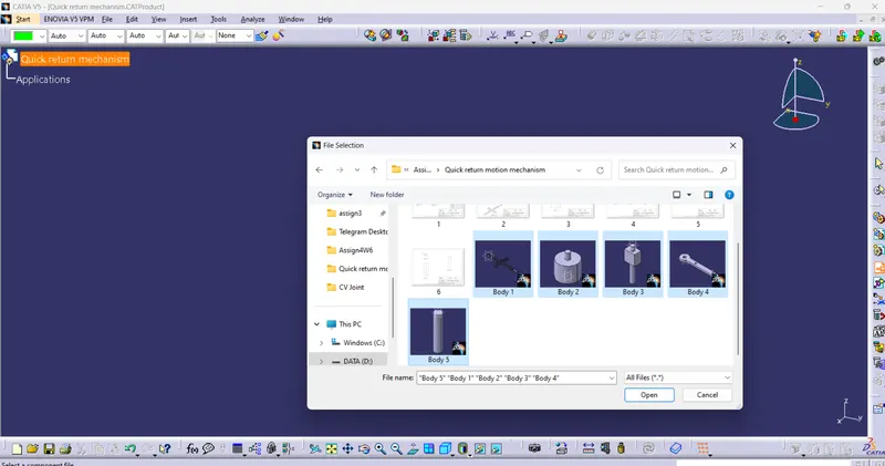
The mechanism consist of 5 body, so the first step is to create 5 body seperately.
Then the parts are inserted in to assembly workbench
Then one part is fixed and assemble other parts respect to fixed parts.
Use constrain tool, fist constrain required part and fixed part ,then update.use offset tool then fixed properly, now assemble the first part.
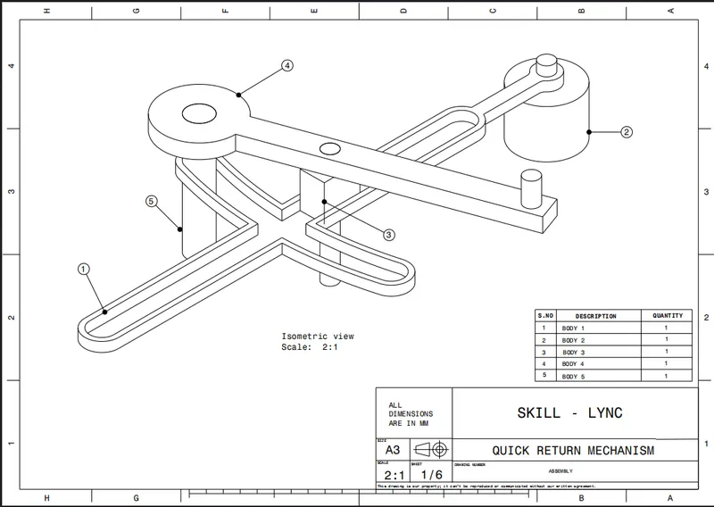
PROCEDURE
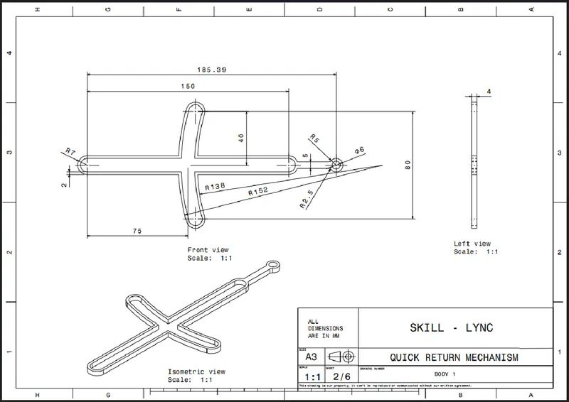
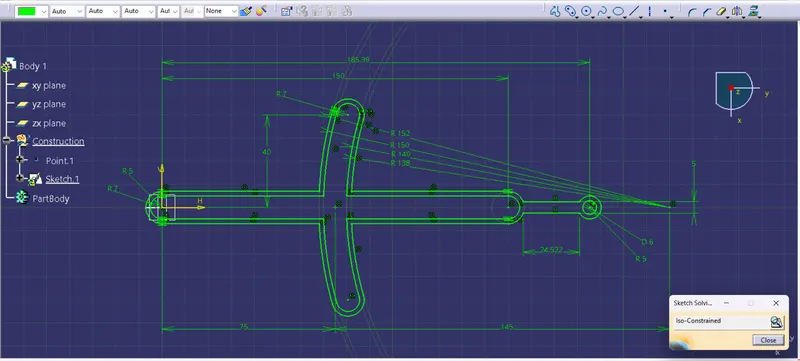
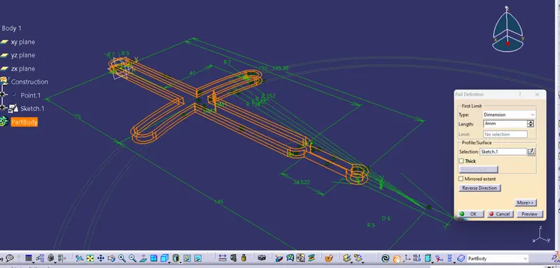
Step 1 : Make each body according to the drawing
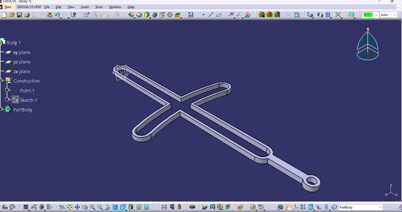
Body 1 :
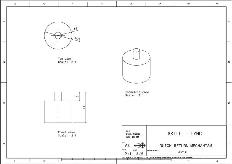
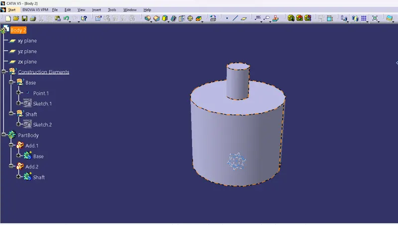
Body 2 :
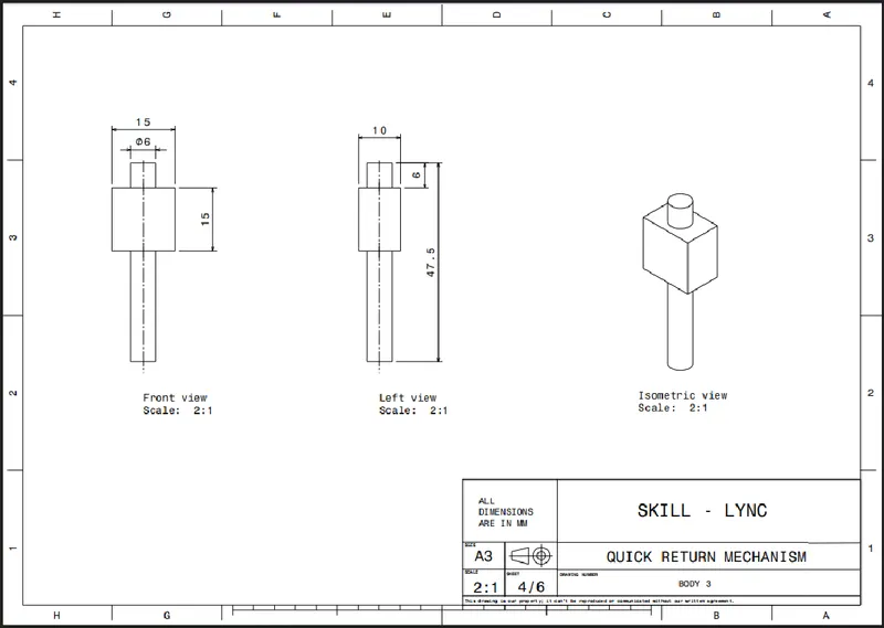
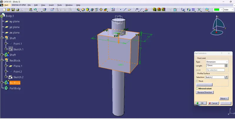
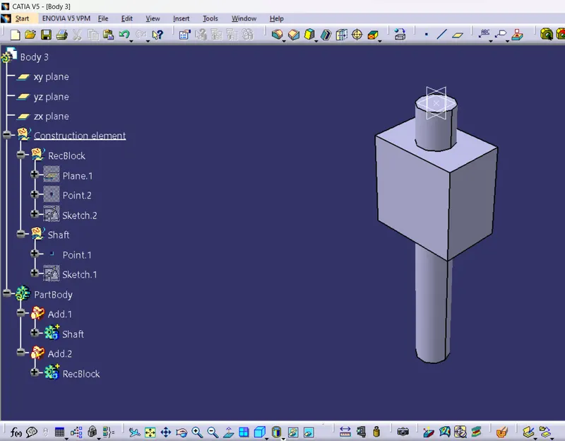
Body 3 :
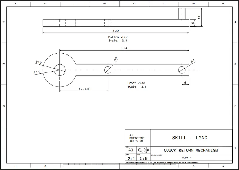
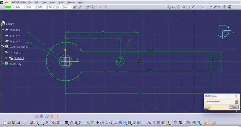
Body 4 :
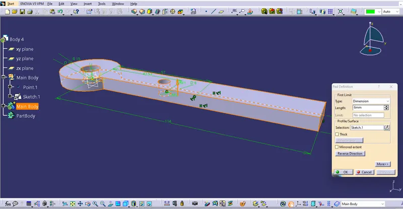
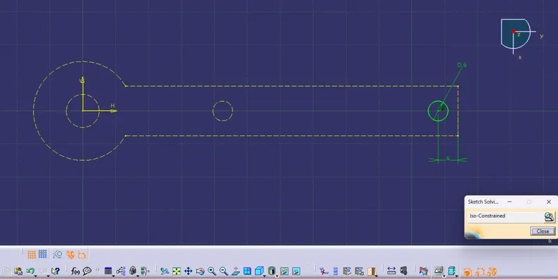
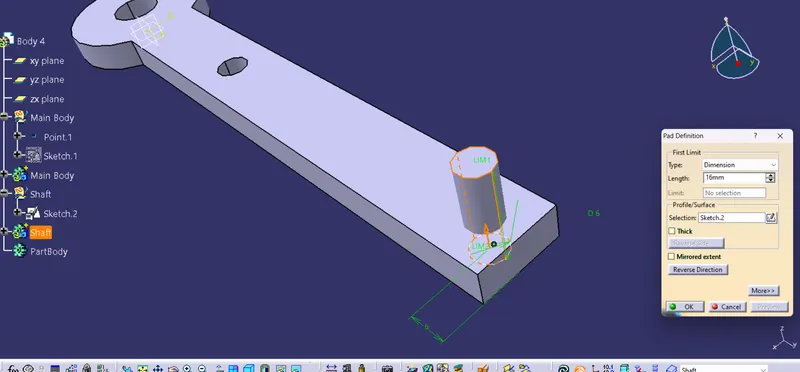
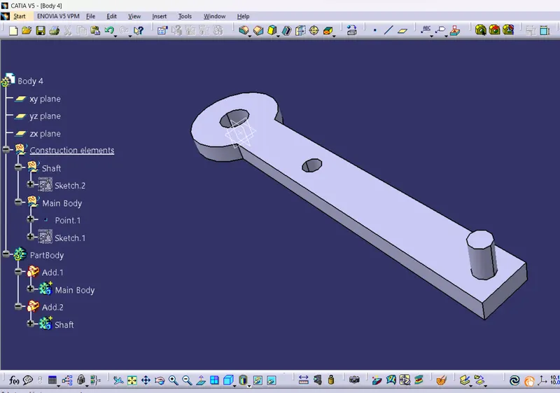
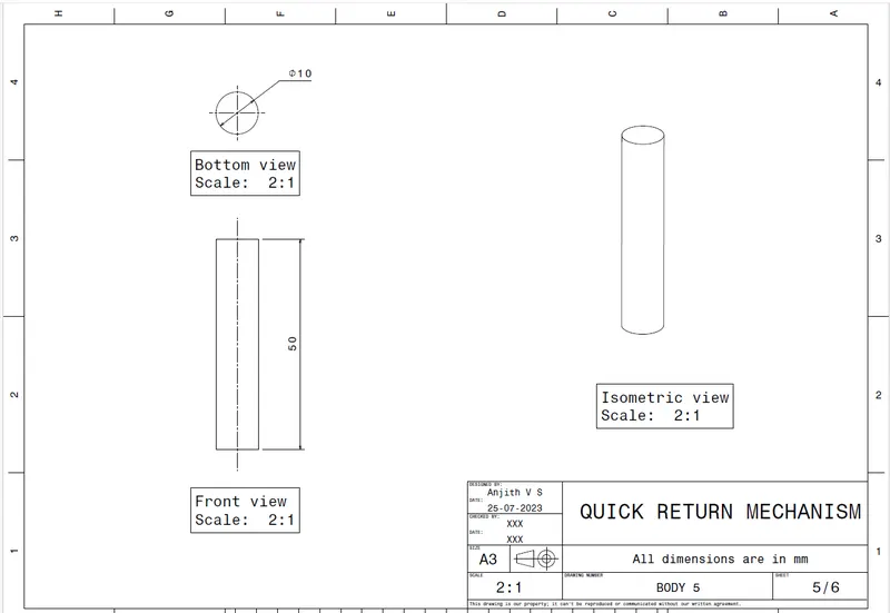
Body 5 :
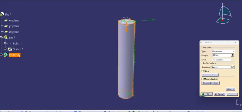
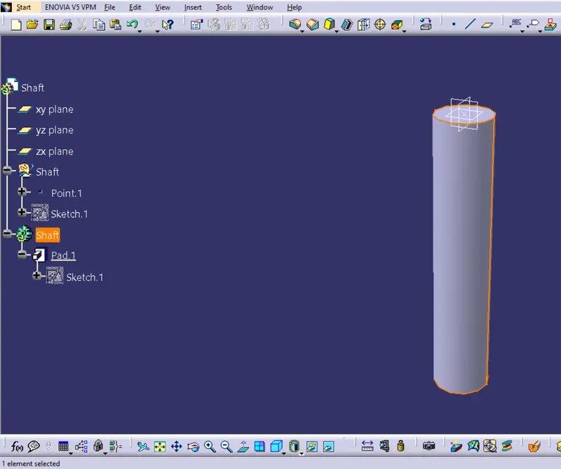
Step 2 : After making all the required bodies bring all the bodies into assembly workbench using 'Existing component' command
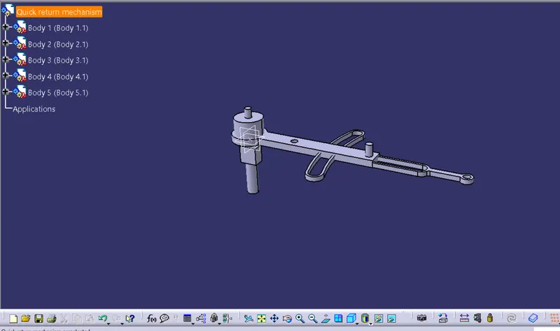
Step 3 : Move each body using 'Manipulation' command and then assemble the parts
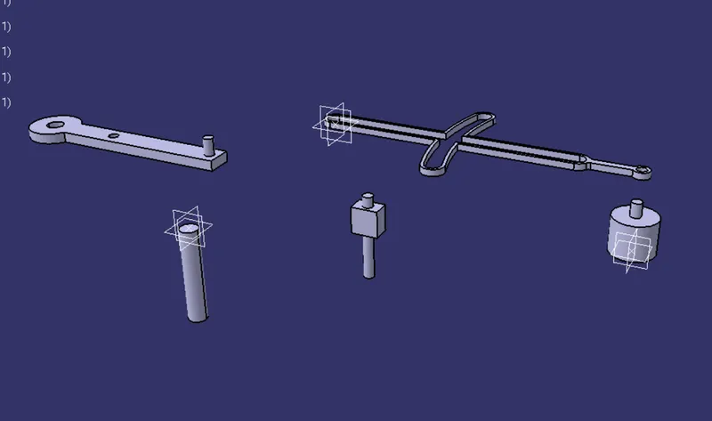
Step 4 : Create another part using 'Part command' which will be the parent of the assembly with zero point
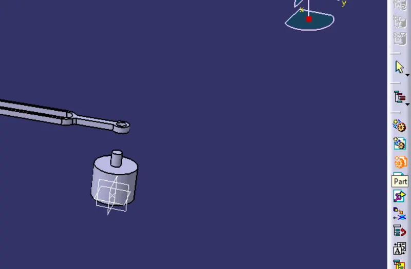
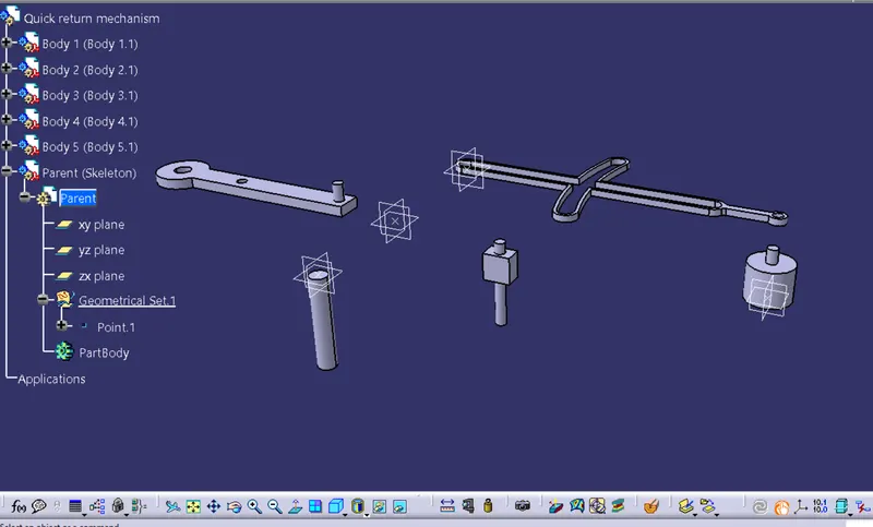
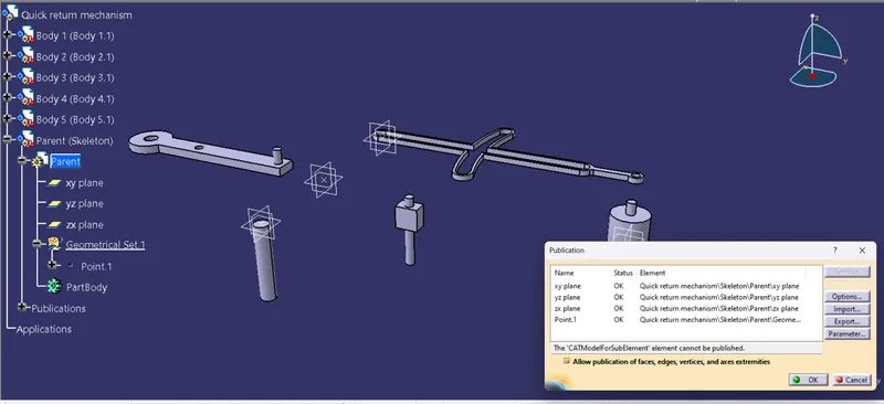
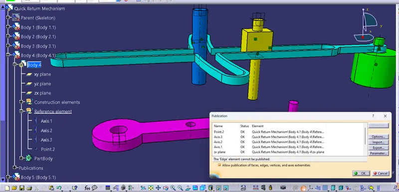
Step 5 : Now publish the planes and the points using 'Publications' from the 'Tools'
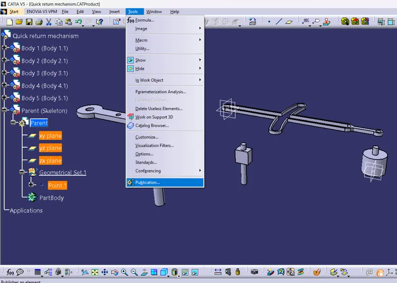
Step 6 : Fix the Parent using 'Fix Component' command and then Create reference axis and reference point for each body by going into 'Generative Shape Design' workbench. 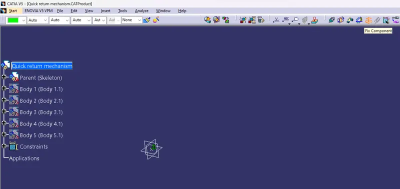
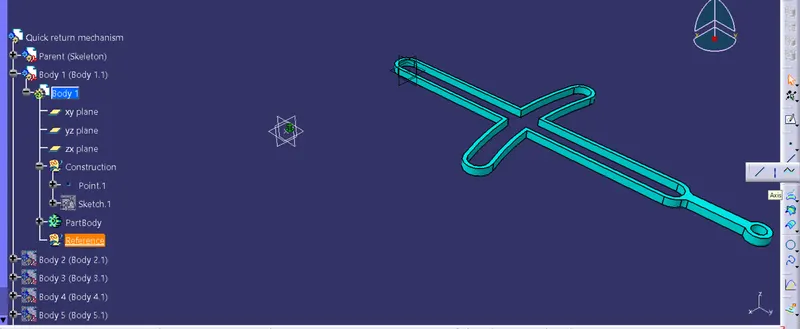
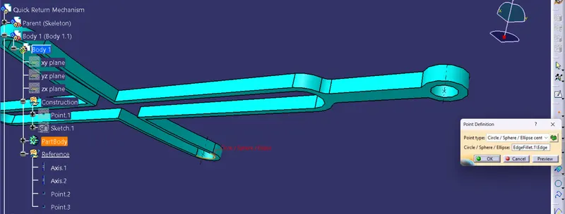
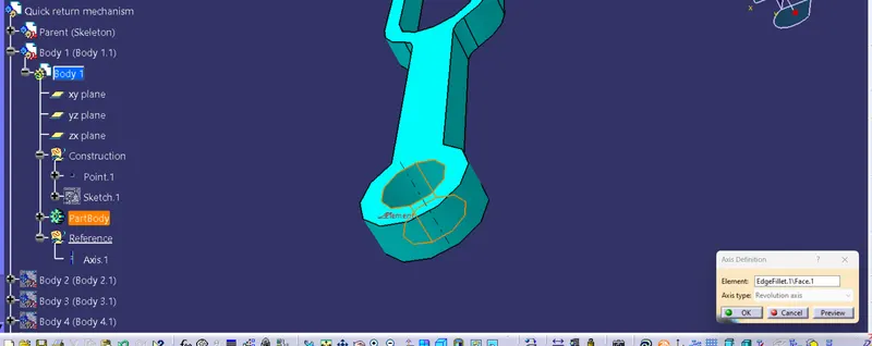
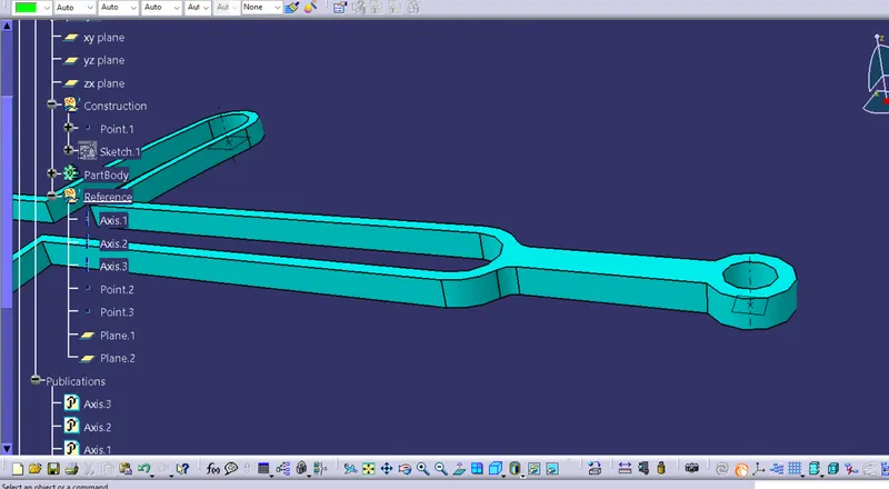
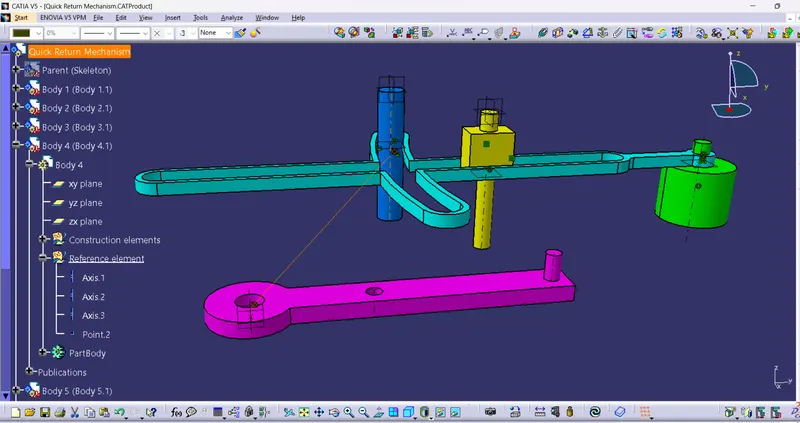
Step 7 : Using 'Coincidence Constrain' the point on the body and the fixed point of parent is selected and after that update is done.
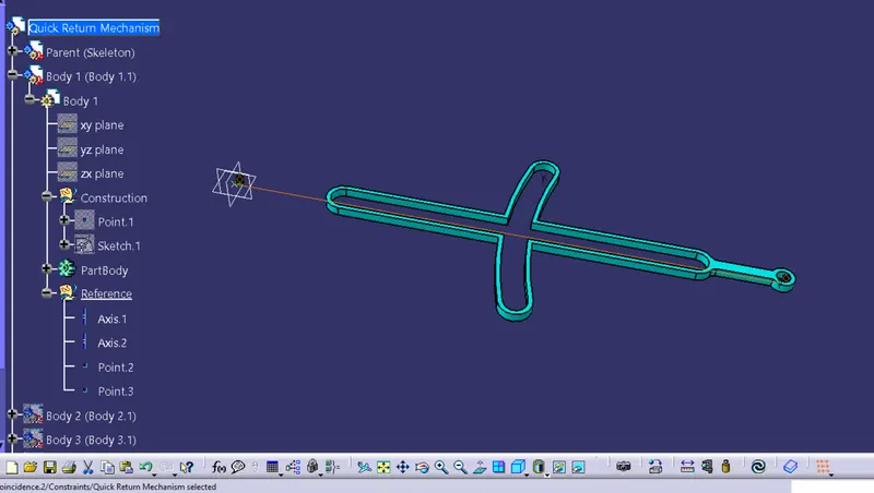
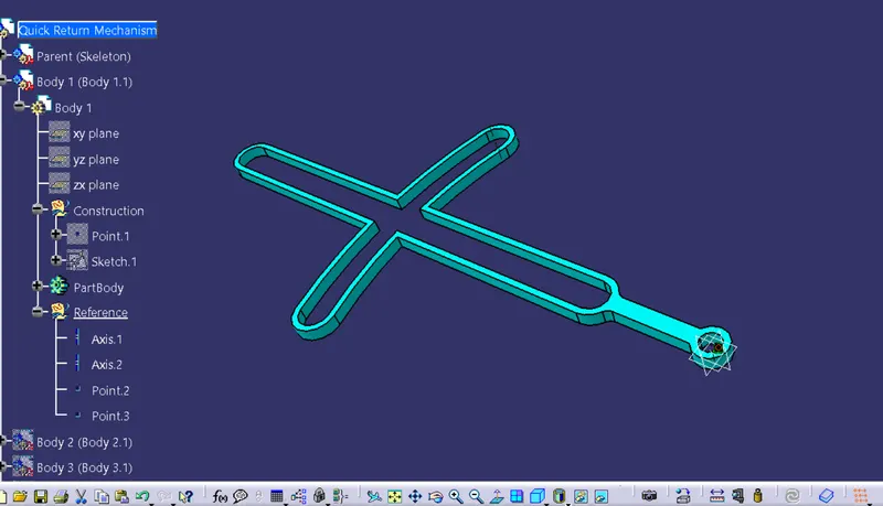
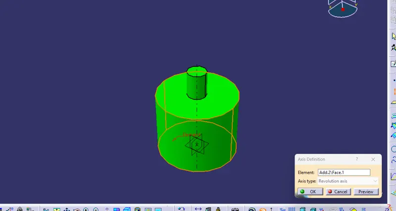
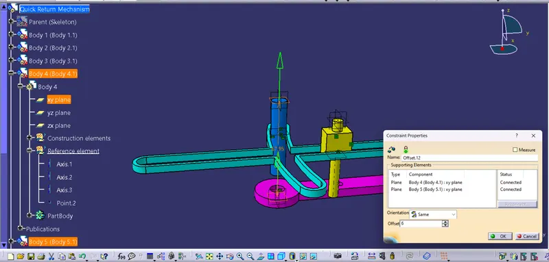
Step 8 : Using 'Coincide Constrain' allign the part and also by using 'Offset Constrain' command
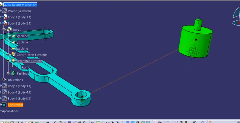
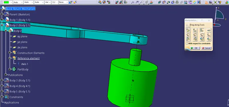
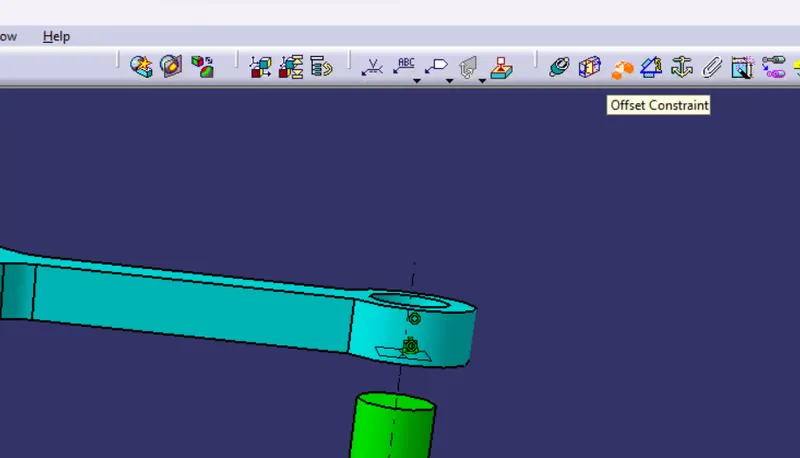
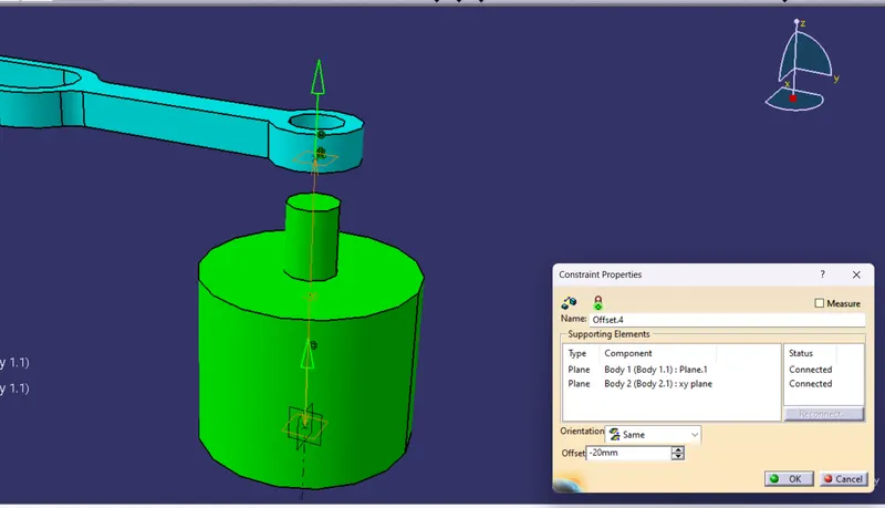
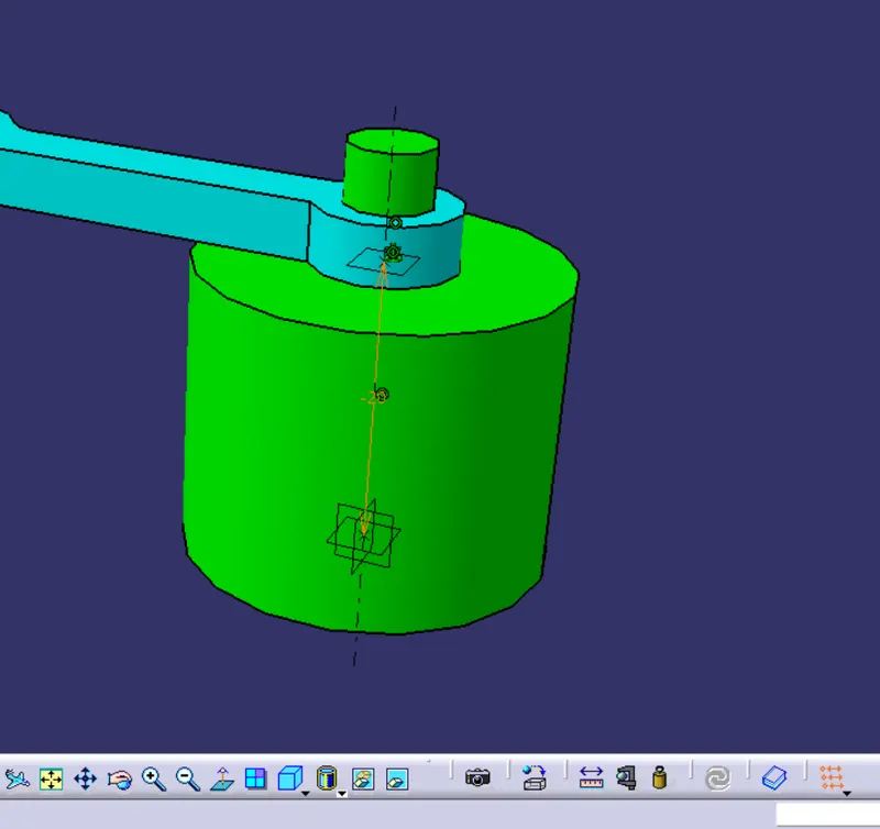
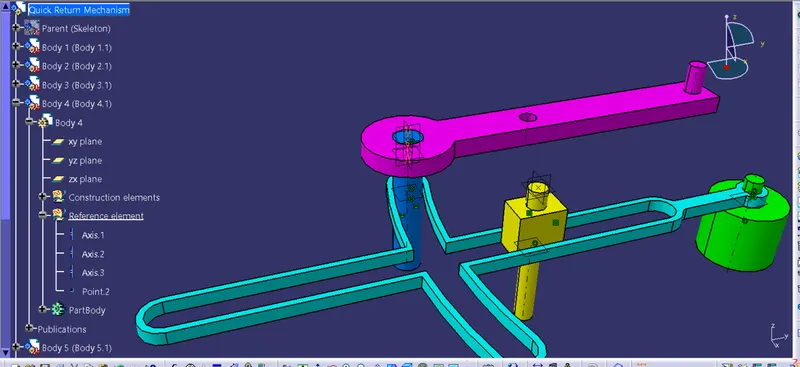
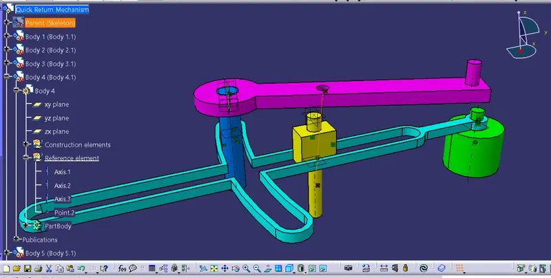
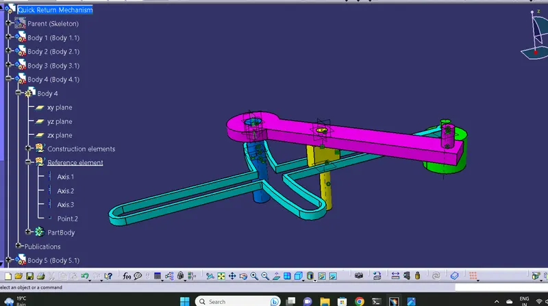
For this body two constrains are given one is constrain with the plane and other is constrain with surface.Since the body has to slide along the sloted area.
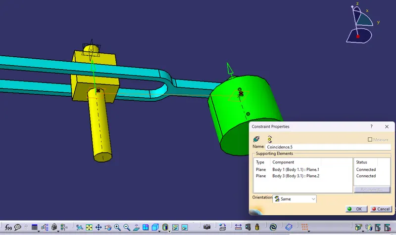
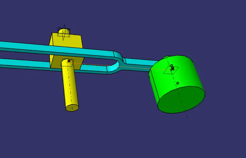
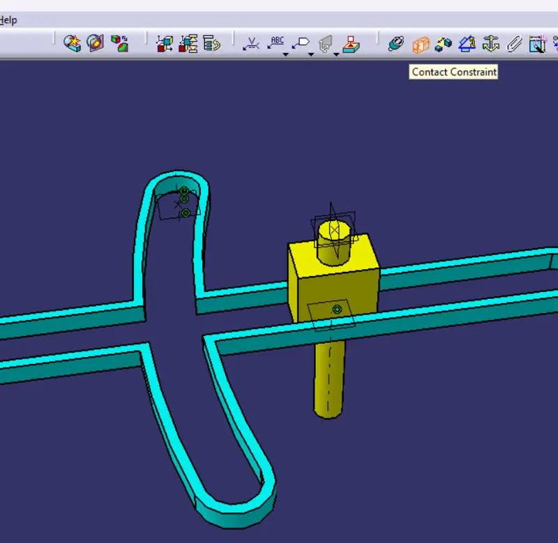
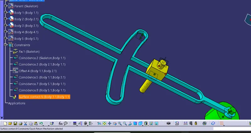
For this part also we are giving coincidence constrain with the plane and contact constrain with the surface.
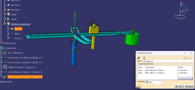
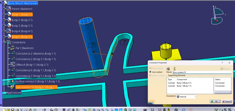
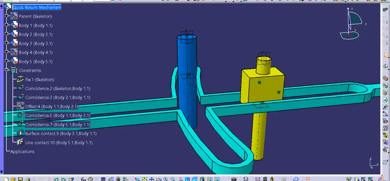
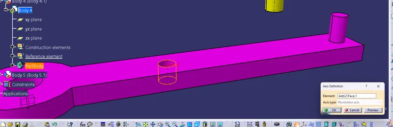
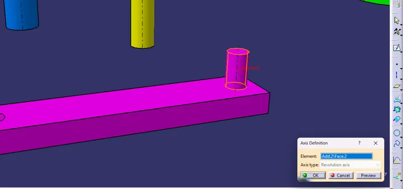
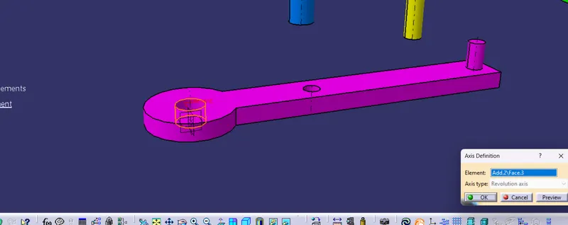
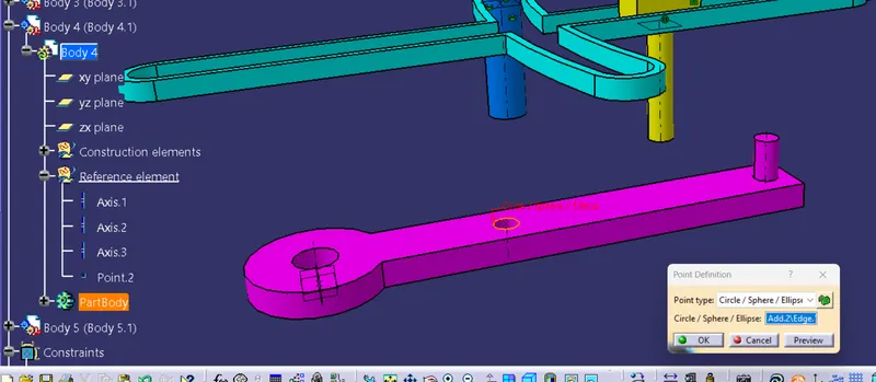
Publishing the reference points,axis and planes
Coinciding the axes and plane
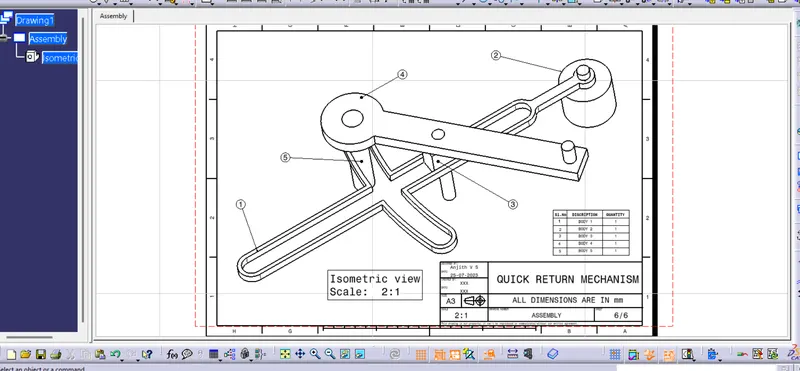
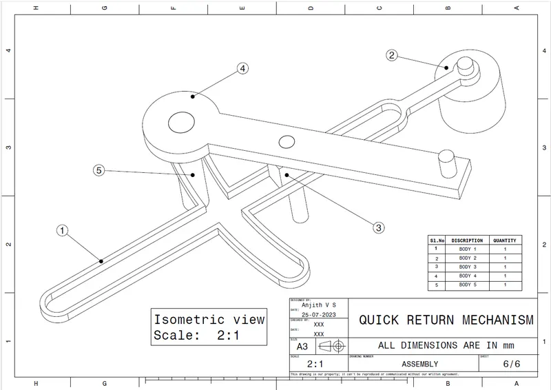
Drafting for the parts and assembly
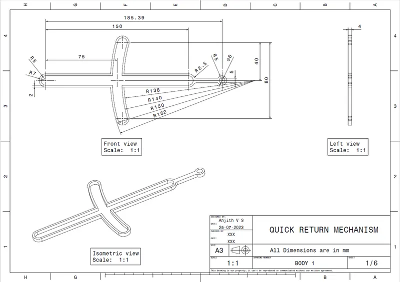
Body 1 :
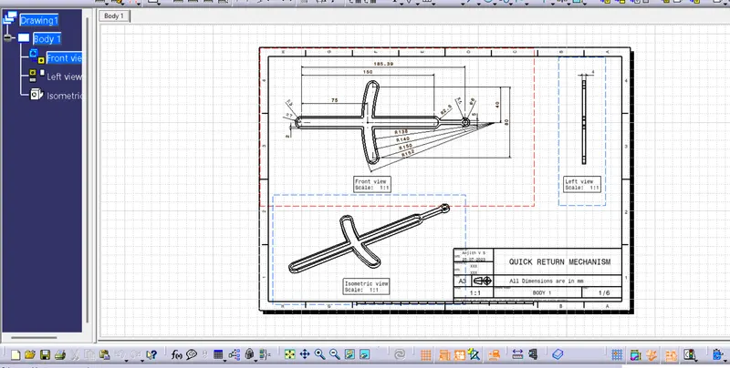
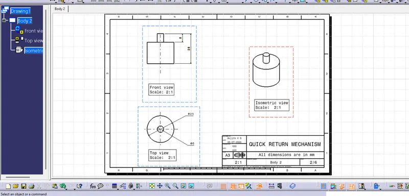
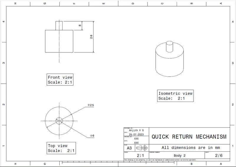
Body 2 :
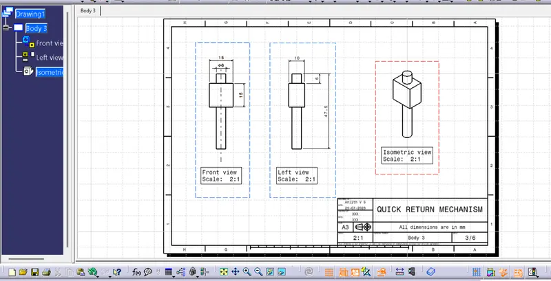
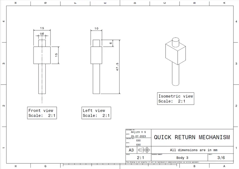
Body 3 :
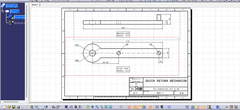
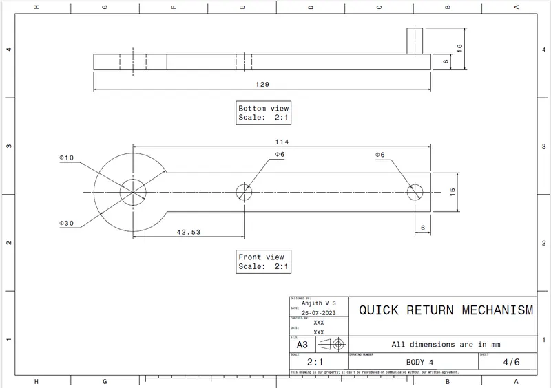
Body 4 :
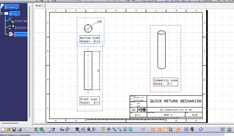
Body 5 :
ASSEMBLY
THEORY
Model 2 - CV Joint
A CV joint, or Constant Velocity joint, is a vital part of front-wheel drive and all-wheel drive vehicle drivetrains. It ensures seamless torque transfer from the transmission to the wheels while accommodating suspension movements. By maintaining a constant velocity, the CV joint allows smooth power delivery without vibrations during turns or suspension travel. Comprising steel balls, bearings, and inner/outer housings, the joint flexes to adapt to changing angles. Over time, wear can lead to clicking or popping noises, necessitating CV joint or axle replacement. In essence, CV joints play a crucial role in enabling efficient power transmission and stable maneuverability in modern automotive systems.
PROCEDURE
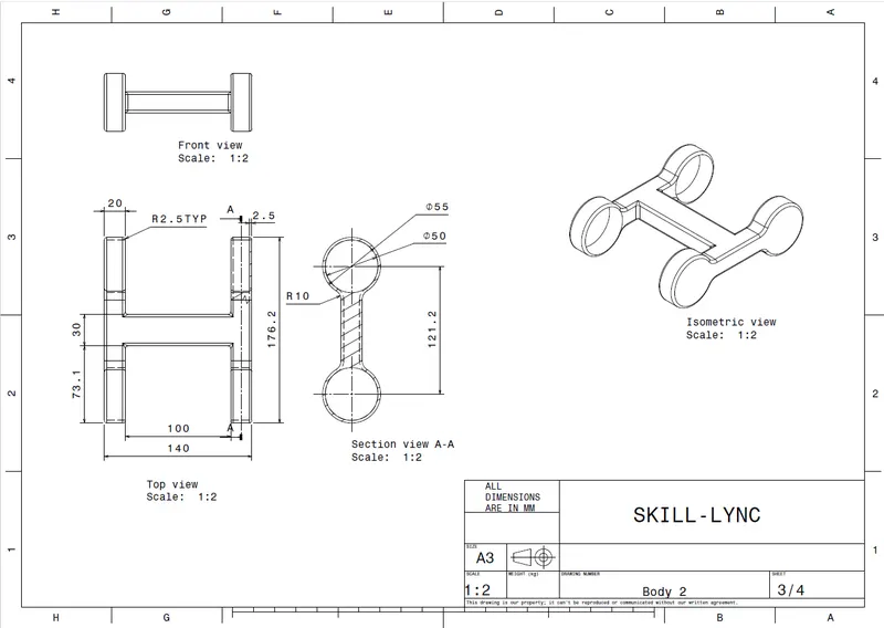
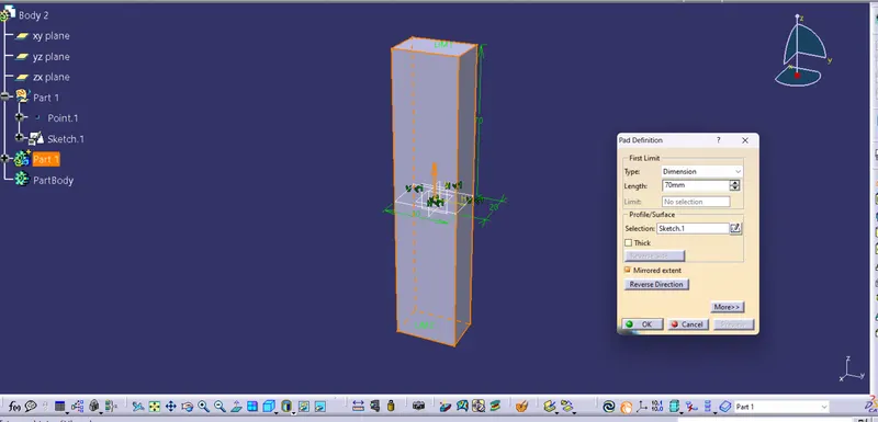
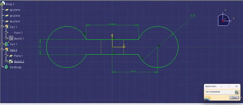
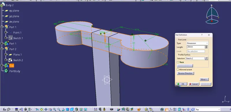
Step 1 : Make each body according to the drawing
Body 1 :
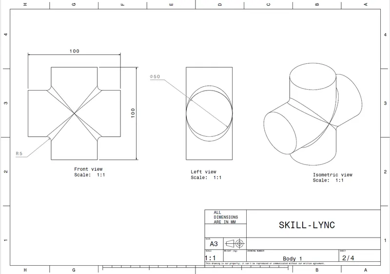
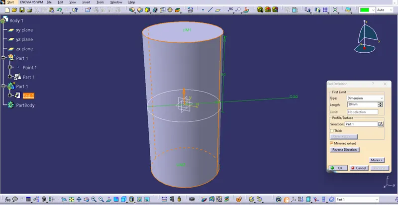
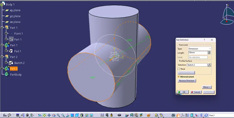
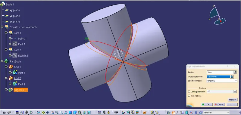
Body 2 :
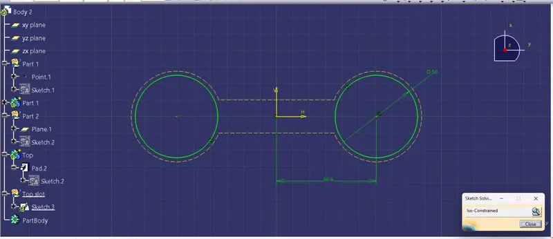
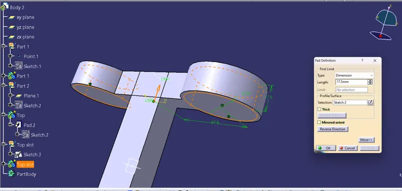
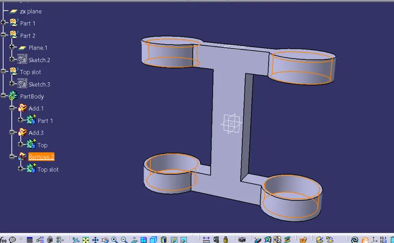
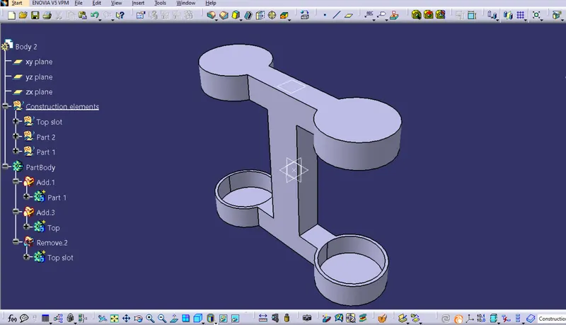
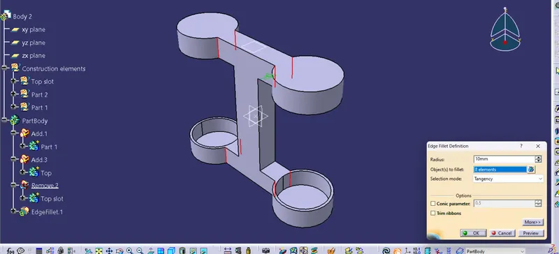
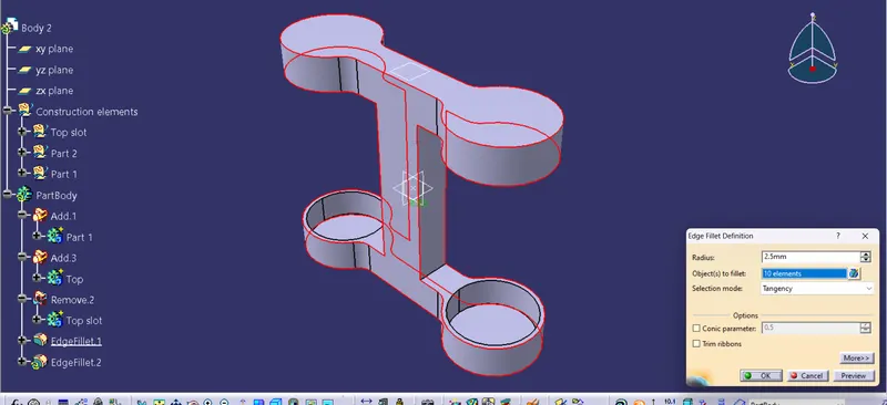
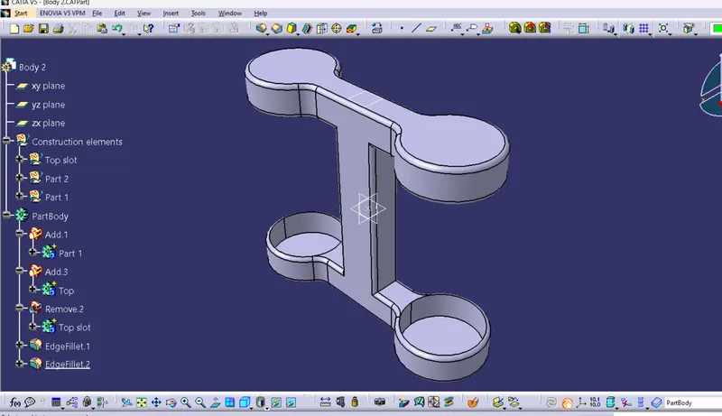
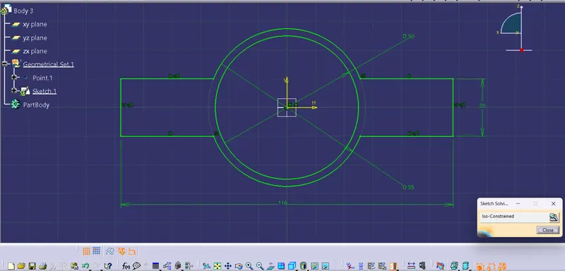
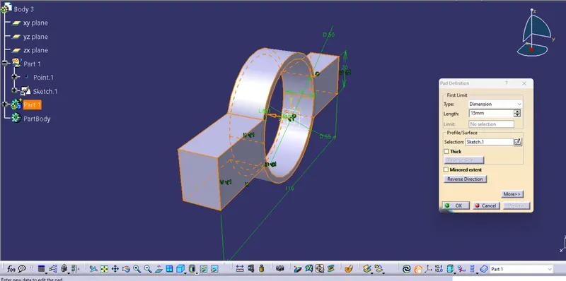
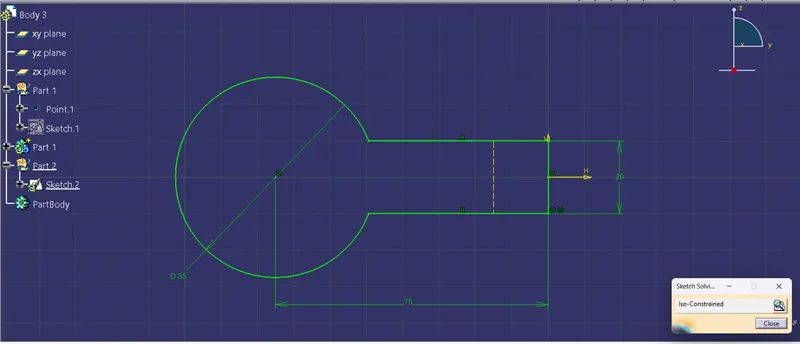
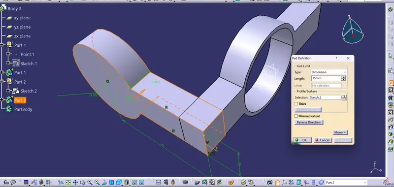
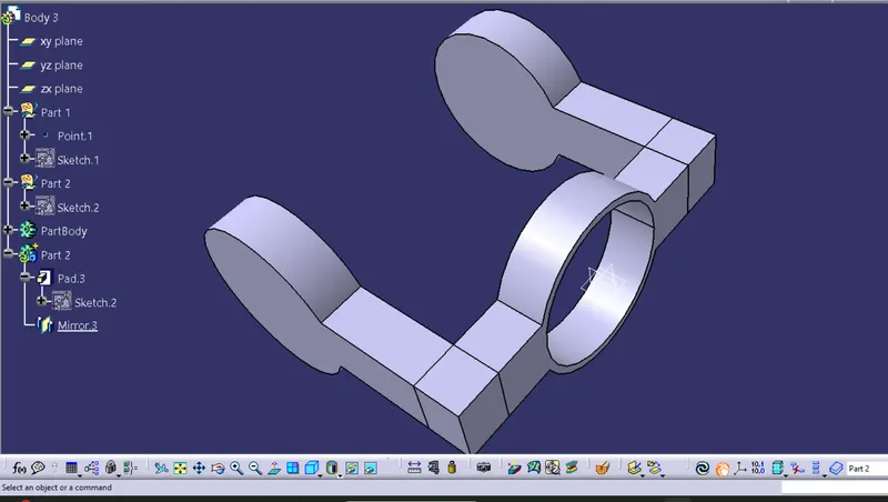
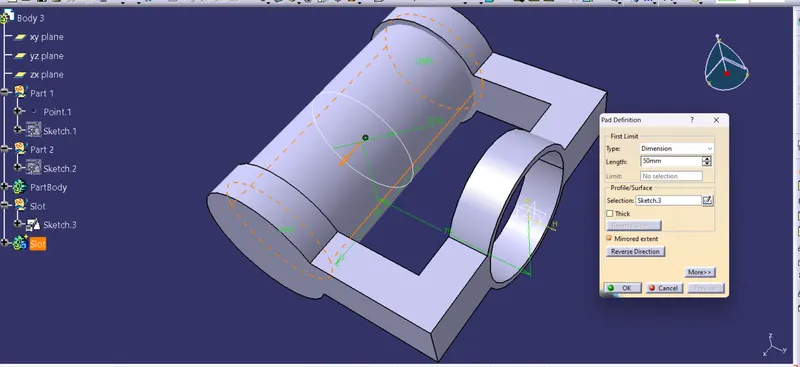
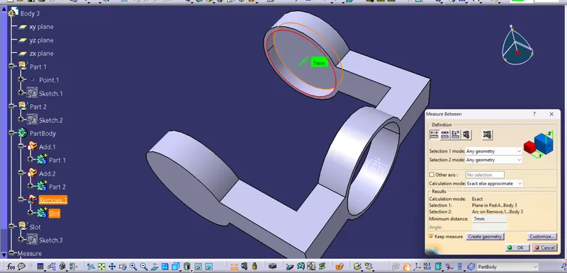
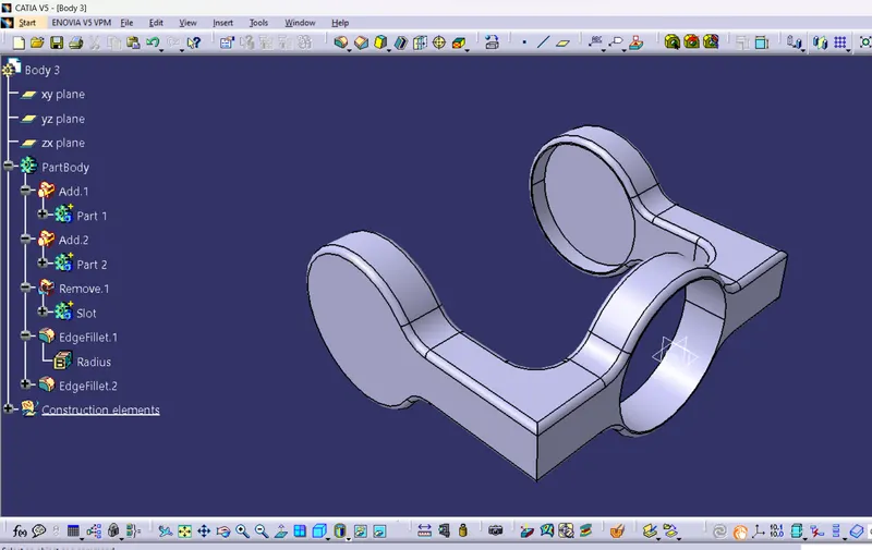
Body 3 :
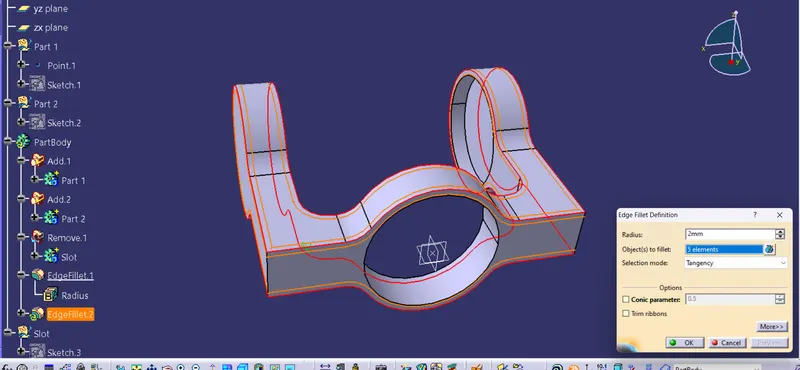
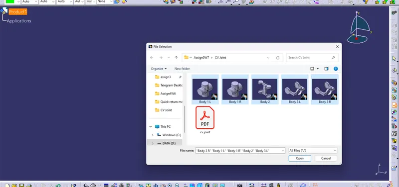
Step 2 : After making all the required bodies bring all the bodies into assembly workbench using 'Existing component' command
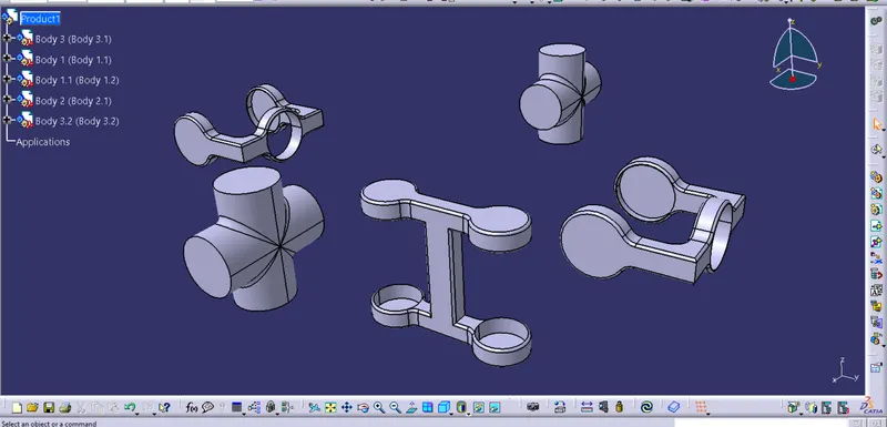
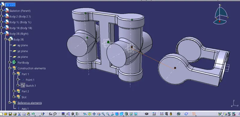
Step 3 : Move each body using 'Manipulation' command and then assemble the parts
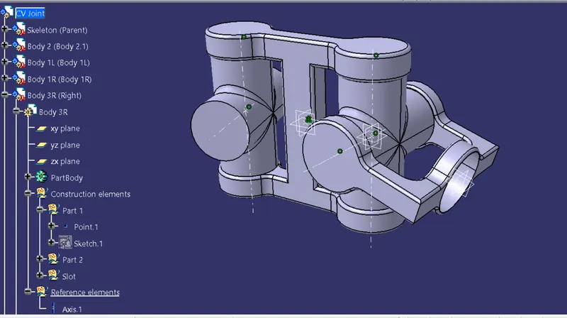
Step 4 : Create another part using 'Part command' which will be the parent of the assembly with zero point
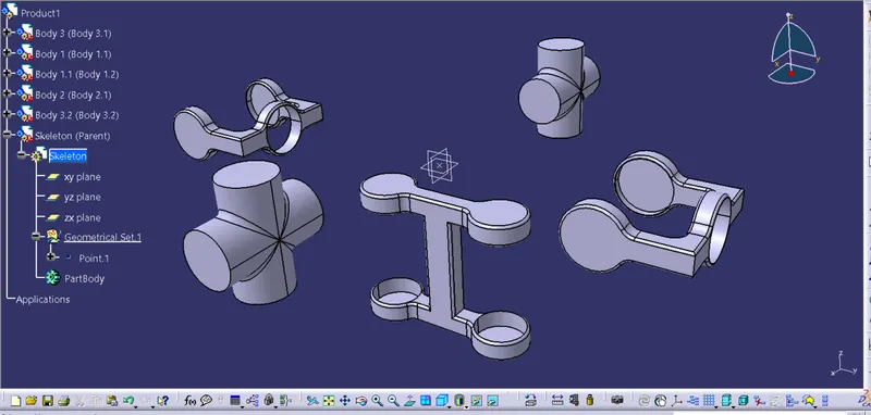
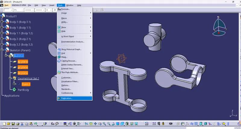
Step 6 : Fix the Parent using 'Fix Component' command
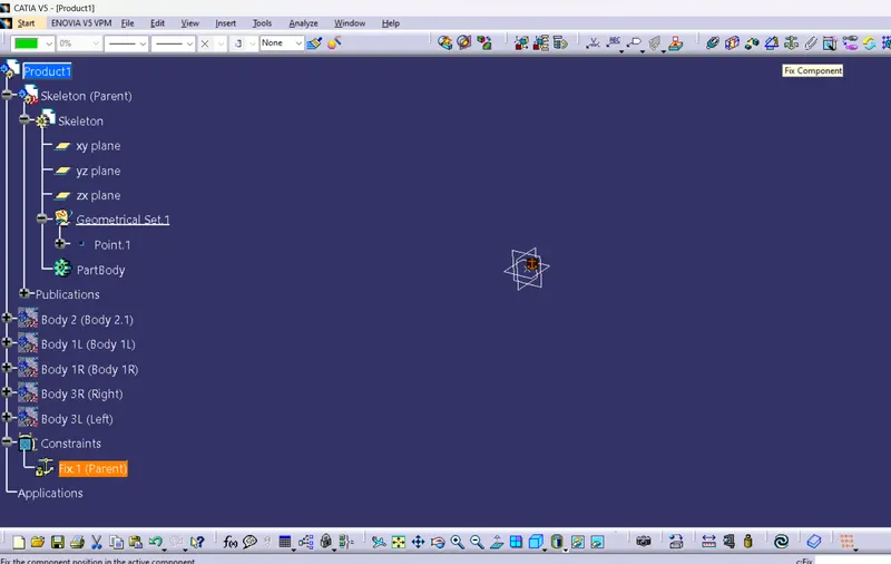
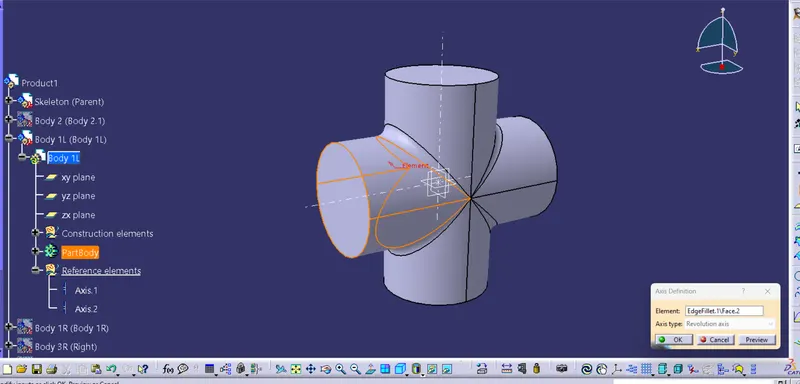
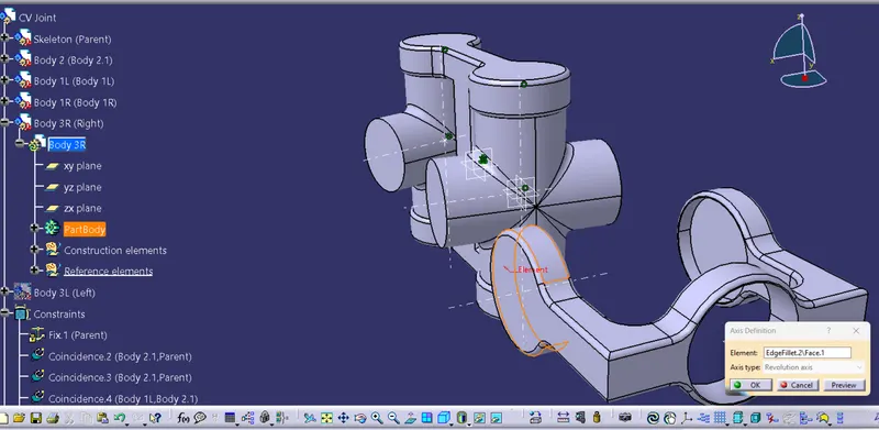
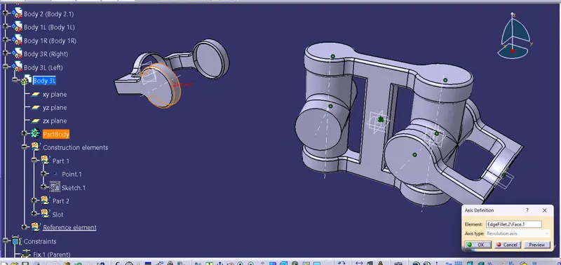
Step 7 : Create reference axis and reference point for each body by going into 'Generative Shape Design' workbench.
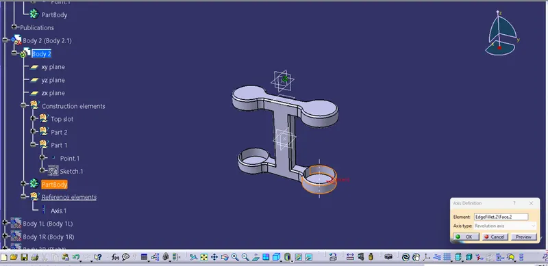
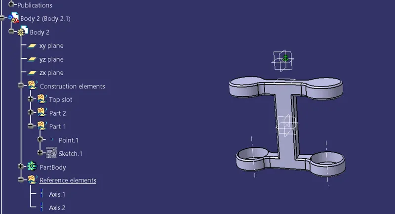
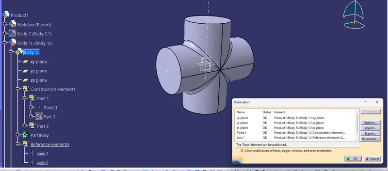
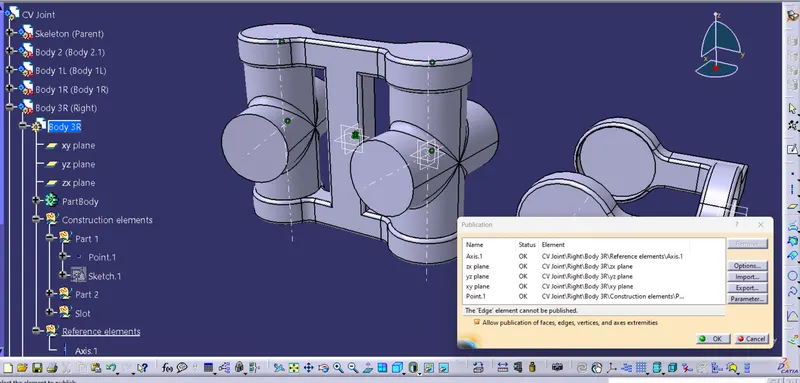
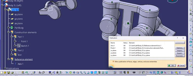
Step 8 : Publish the axeses,planes and points
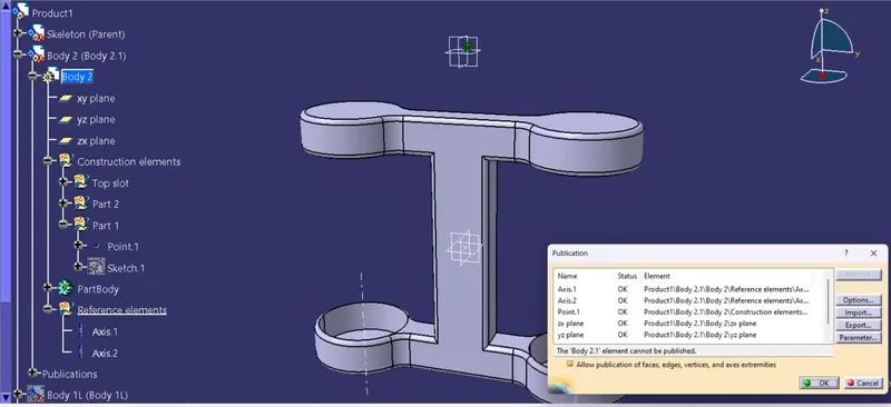
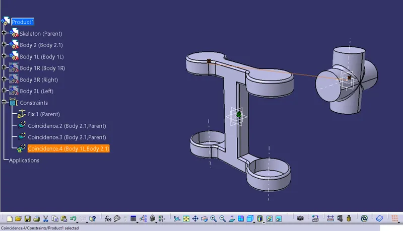
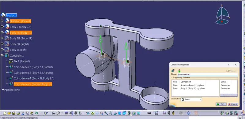
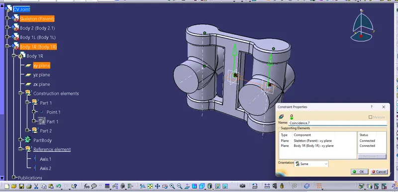
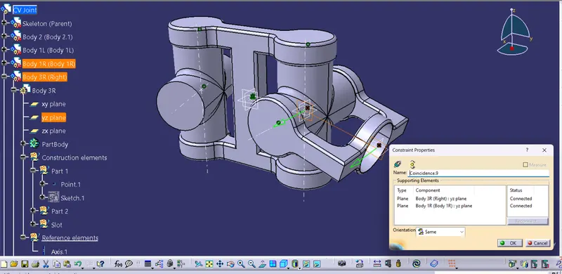
Step 9 : Using 'Coincidence Constrain' the point on the body and the fixed point of parent is selected and also one plane constrain is given and after that update is done.
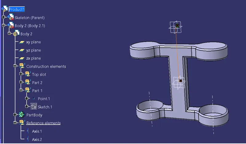
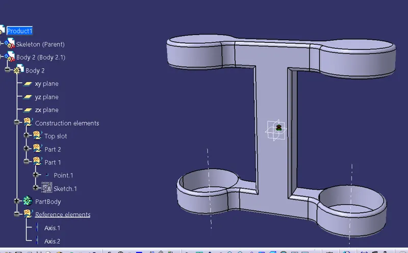
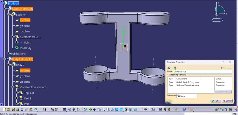
Step 10 : Similarly do for other bodies
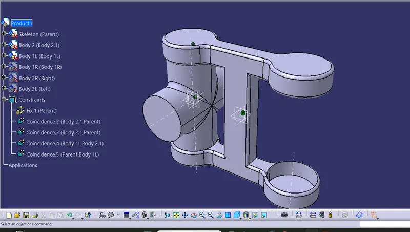
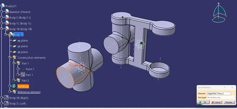
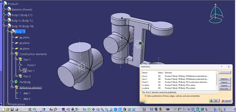
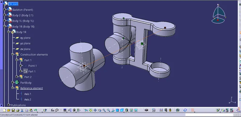
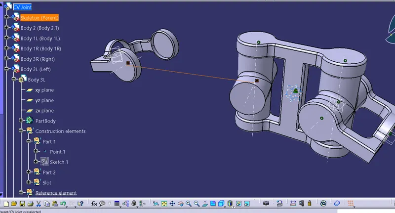
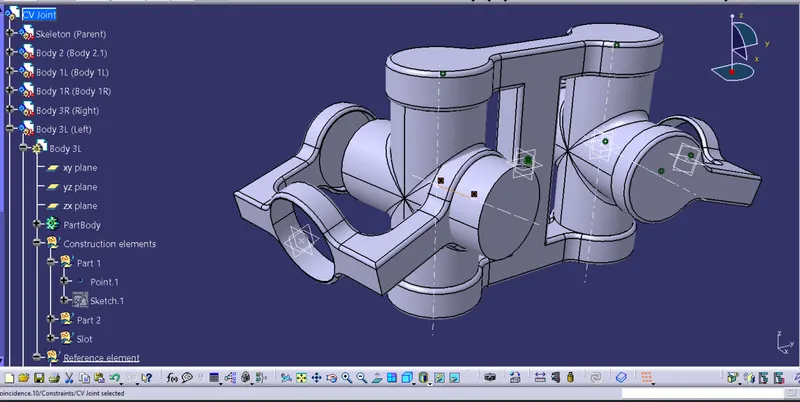
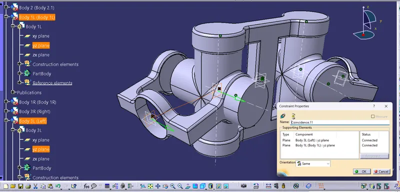
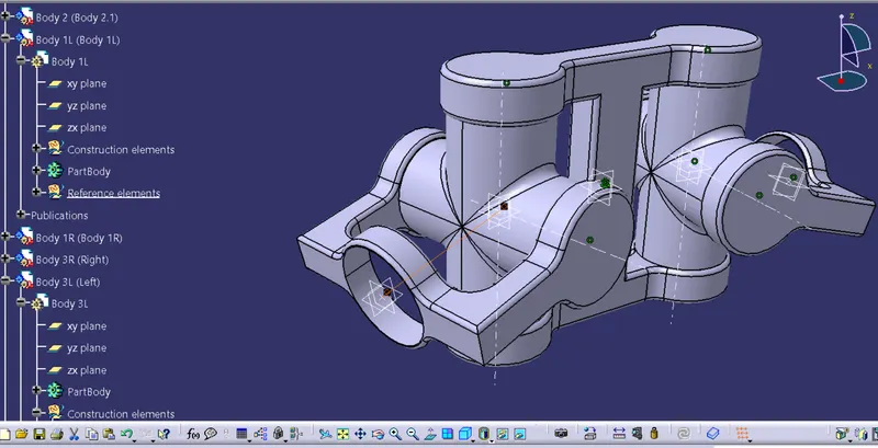
Final Assembly
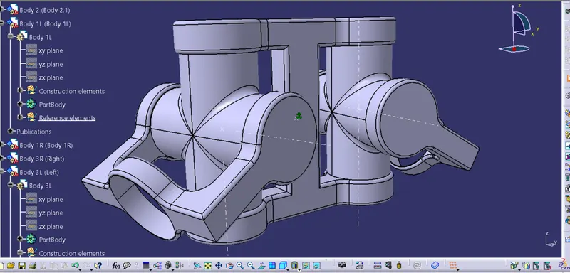
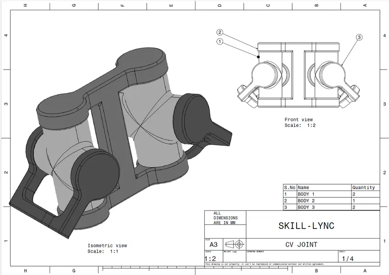
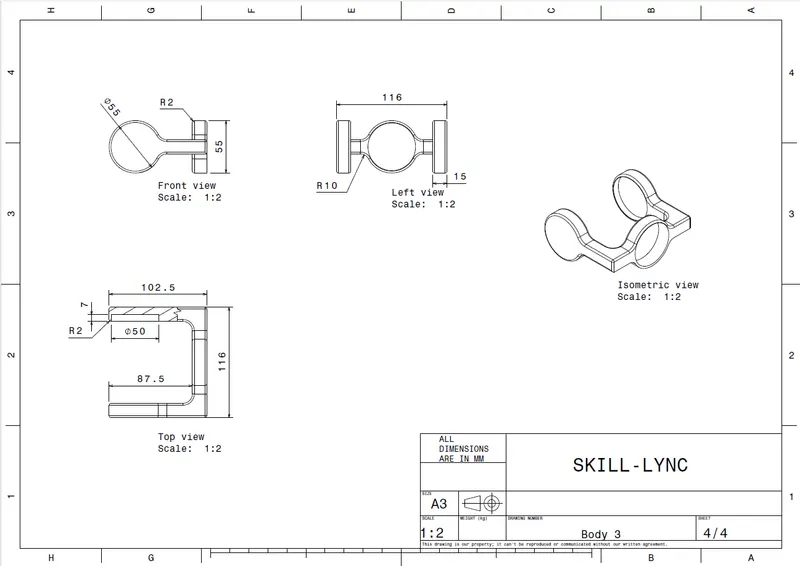
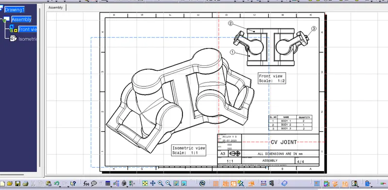
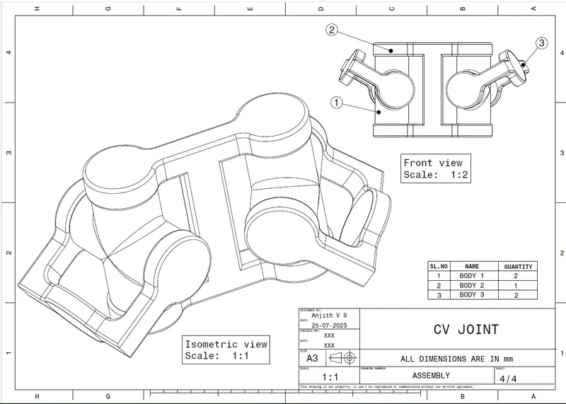
Drafting for the parts and assembly
Body 1 :
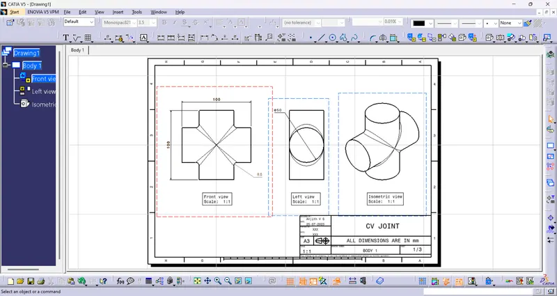
Body 2 :
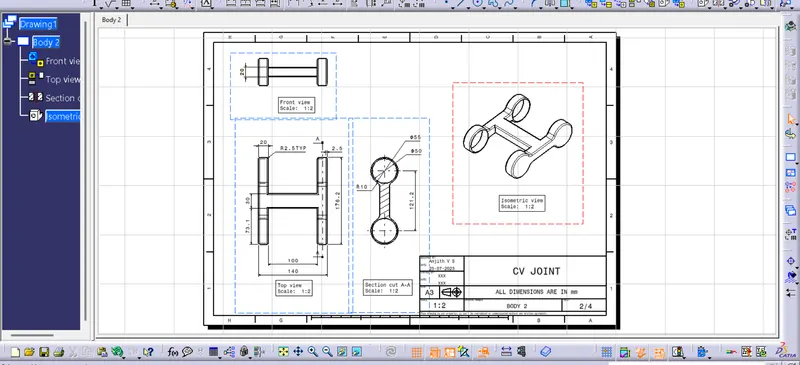
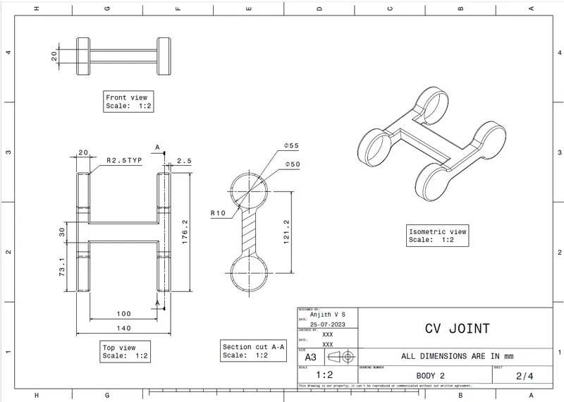
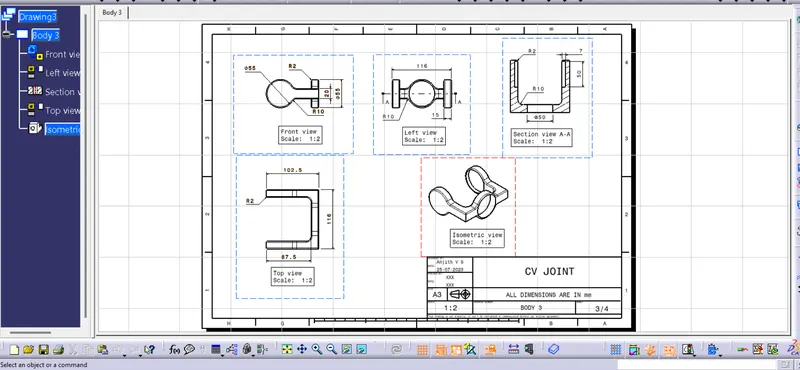
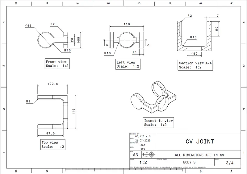
BODY 3 :
ASSEMBLY
CONCLUSION
- Created 2 assemblies from 2D diagrams of the components by creating the individual part files and then create a complete assembly of those part files in the assembly workbench.
- Created 2D drawing after completing the assembly