Wiring harness design in CATIA V5 - 3D modeling Week 5 & 6 Challenge
AIM
- To route the harness layout in Electrical workbench.
- To check the bundle Continuity.
- To add annotation to all connectors.
- To check for the bundle warning.
- To generate CAT.part of harness assembly and convert is in. igs format.
PROCEDURE
Step 1 :
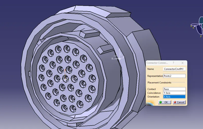
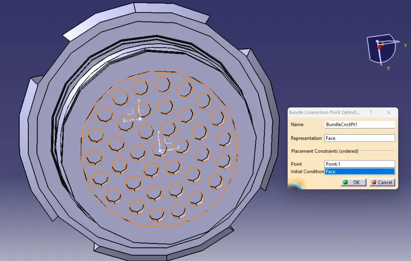
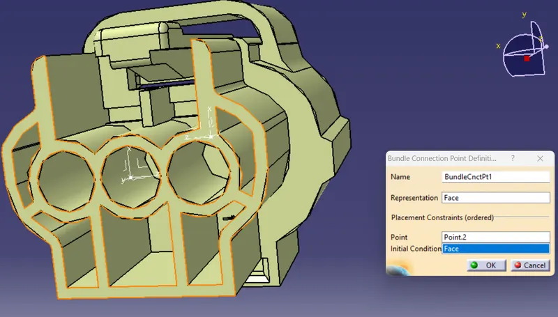
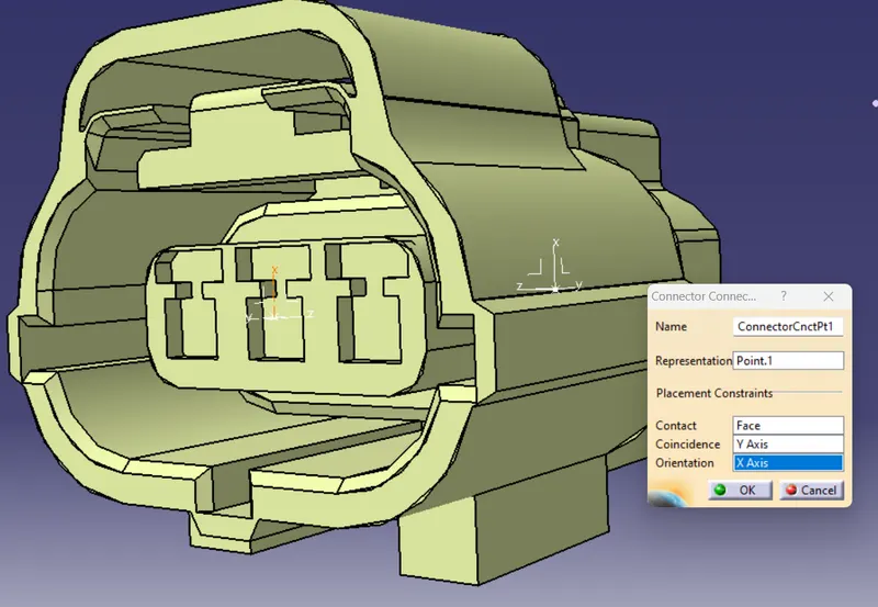
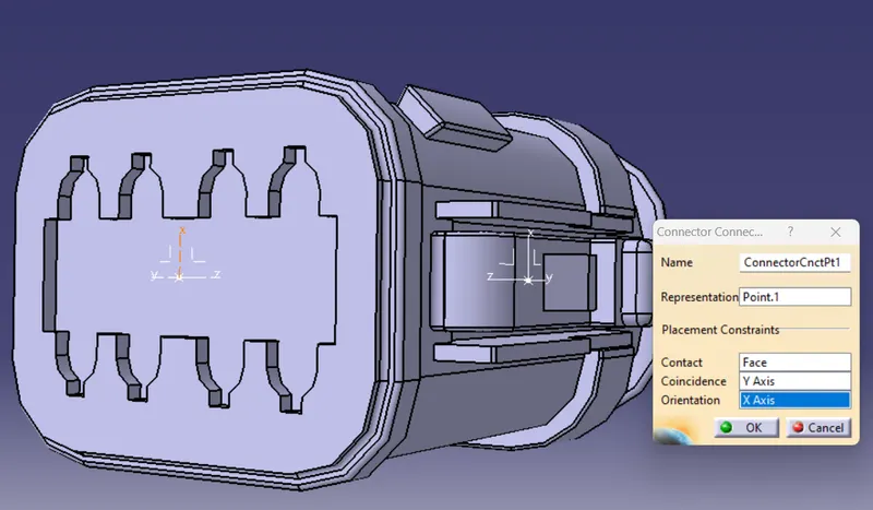
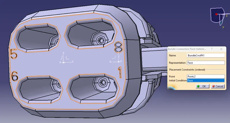
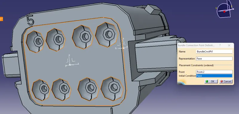
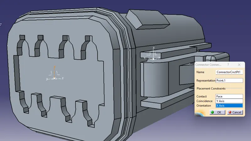
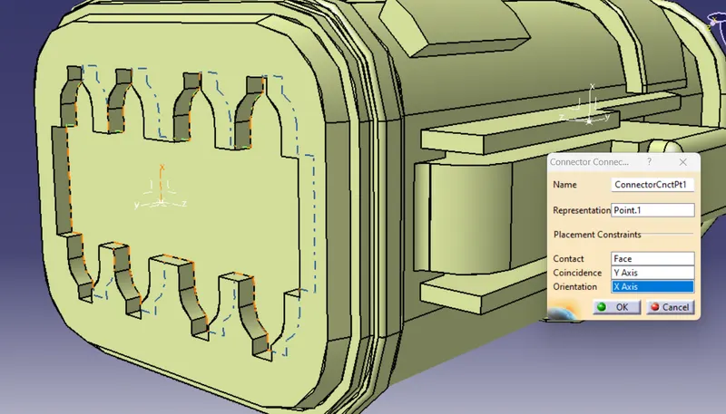
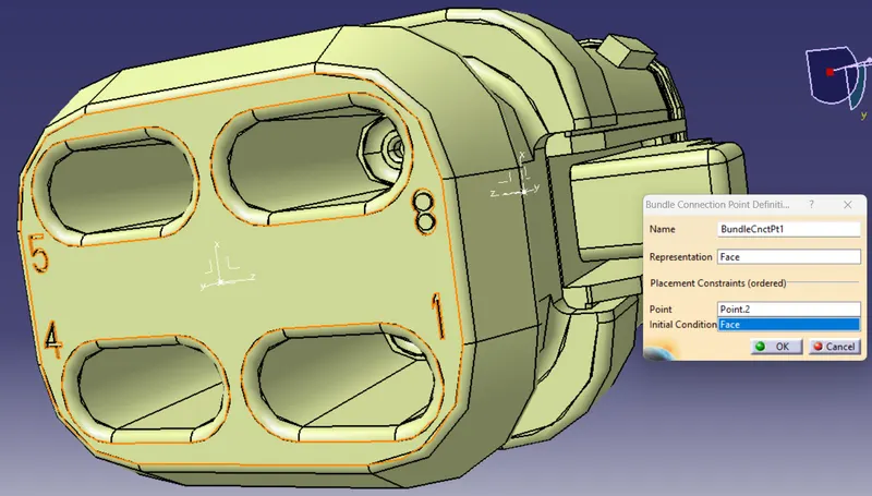
All the connectors are converted to Electrical part from Mechanical part and the Connector connection and Bundle connection parametere were defined along with axis system.
- Each parts are opened as mechanical part and after introducing the axis system for both connector connection point and Bundle connection point
- The workbench is changed to electrical workbench and the mechanical part is defined as electrical connector using 'Define connector' command.
- After converting to electrical part using 'Define Connector connection point' the connection point is defined.
- Then using 'Define bundle connection point' the bundle connection parameters were defined.
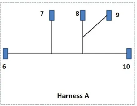
Connectors for Harness A
C-YDTS26F15-35SNV001
C-DT06-08SA-EP07
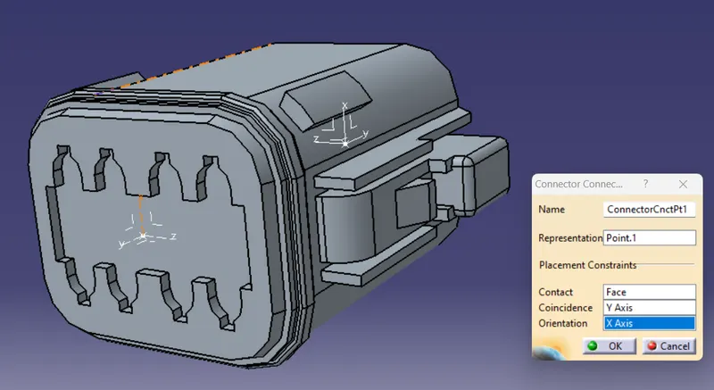
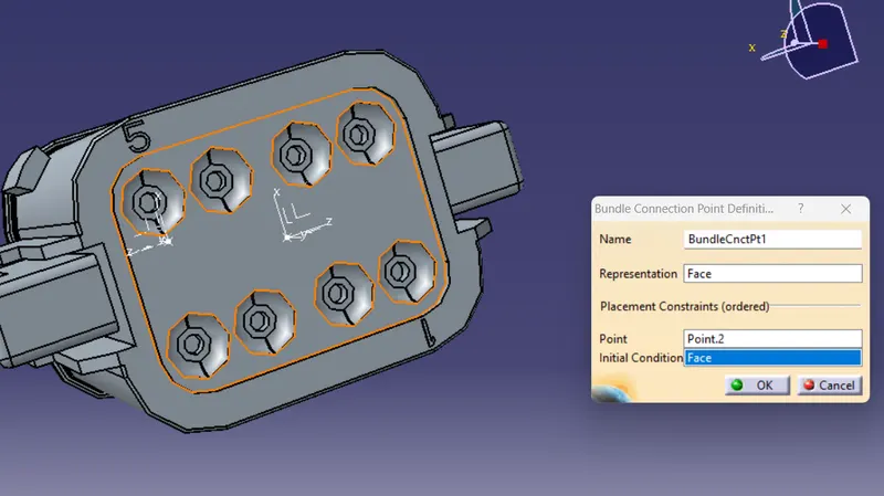
C-DT06-08SA-CE01
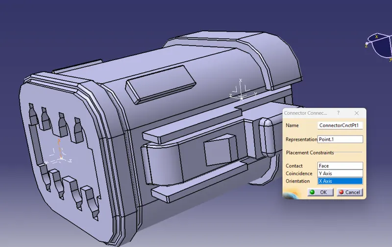
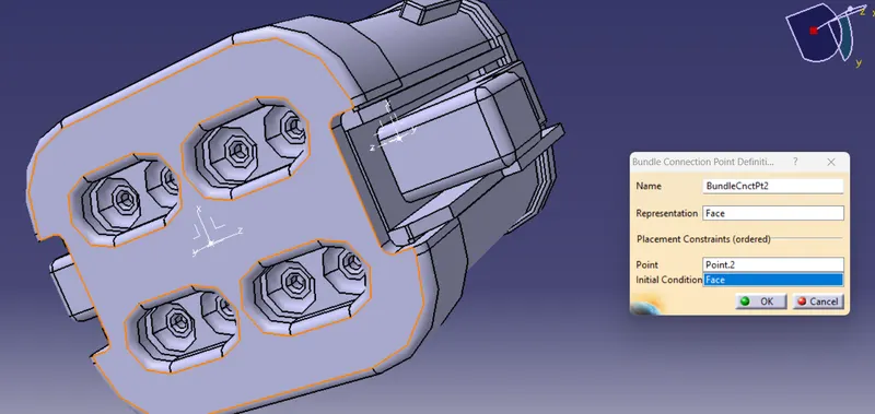
C-DT04-08PA-C017
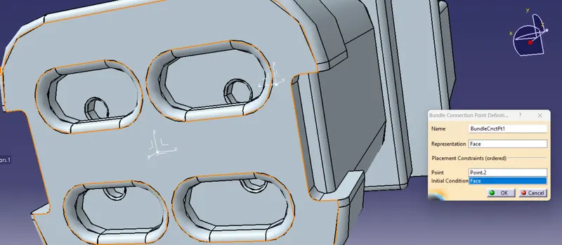
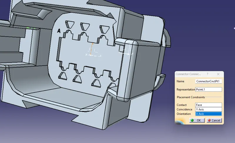
C-1-174357-2
Connectors for Harness B
C-DT06-08SA-CE04
C-DT06-3S-CP01
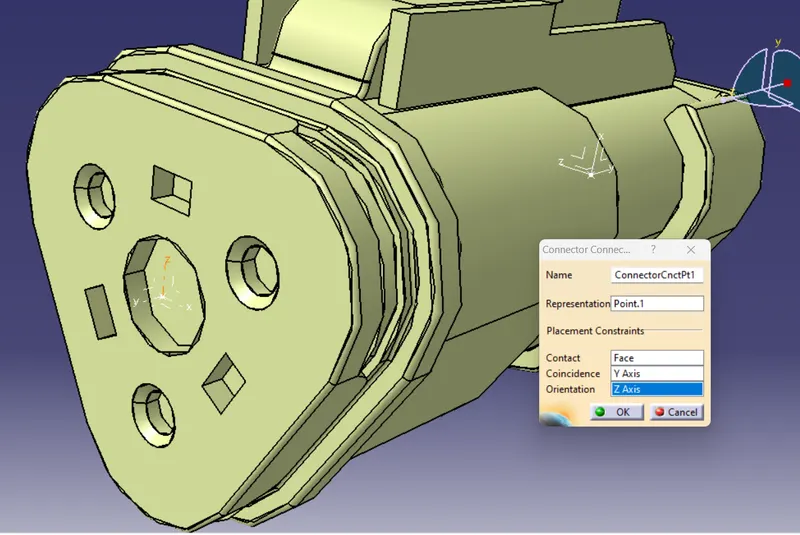
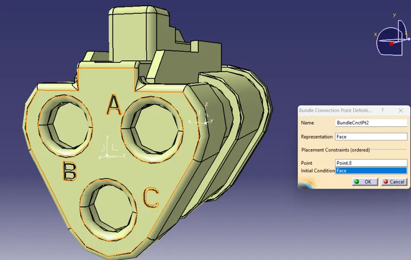
C-YDTS26F15-35SNV001
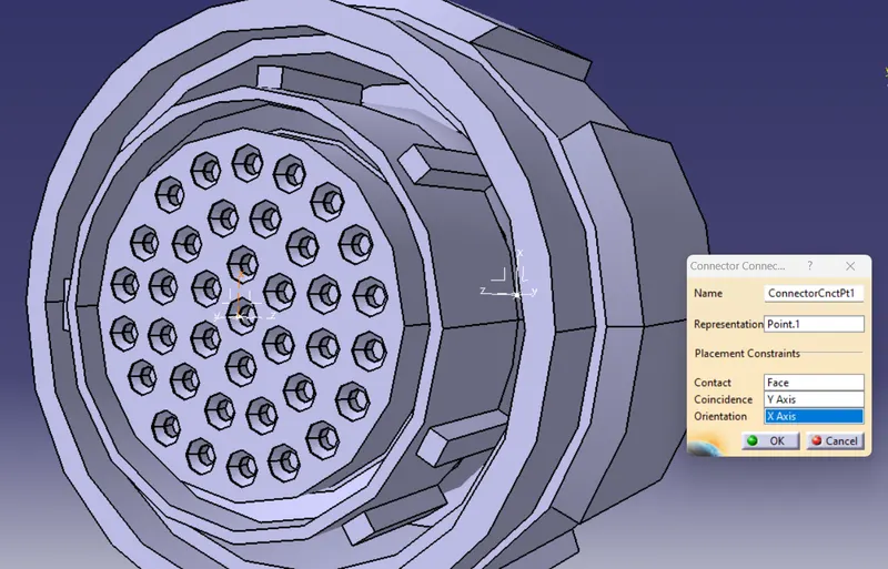
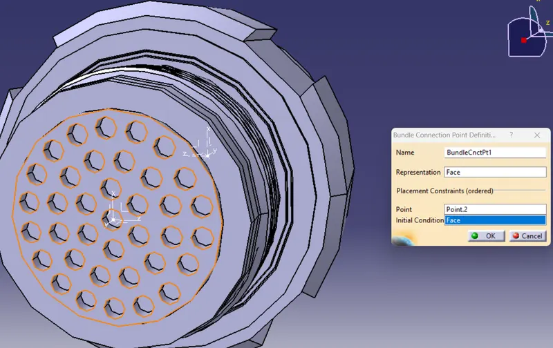
C-DT06-08SA-EP07
C-DT06-08SA-CE13
Step 2 :
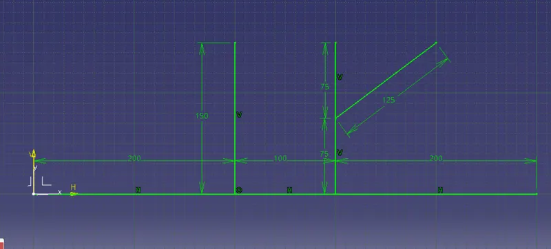
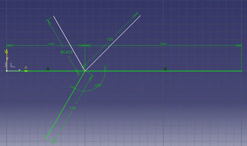
After defining all the connectors with required parameters the path for the wiring harness in space is created using Sketch command.
Harness A
Harness B
Step 3 :
Open all the parts need for Harness A & Harness B in the Mechanical part design workbench and arrange according them according to diagram.
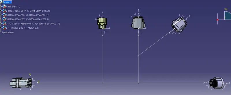
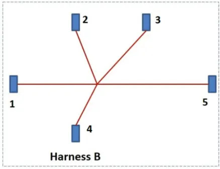
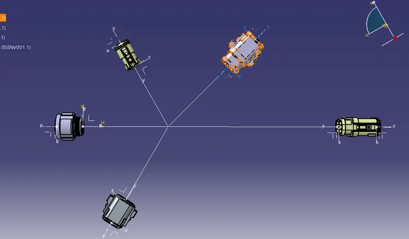
Step 4 :
- Convert Mechanical assembly file to Electrical bundle assembly file.
- Switch to 'Electrical Harness Assembly'.
- Select 'Geometrical bundle command' and click on the file name 'Geometrical bundle' to convert to Electrical bundle assembly file.
- After arranging all the connectors according to diagram, the bundle segment is created.
Step 5 :
- After arranging all the connectors in position now we have to switch to 'Electrical harness installiation' workbench to make the wiring.
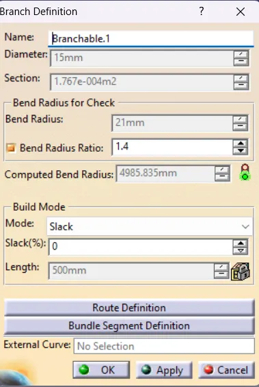
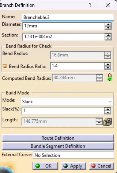
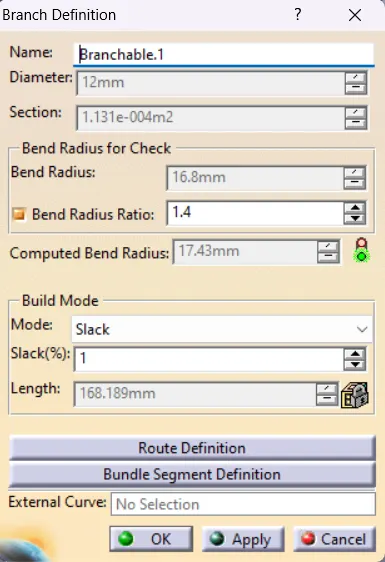
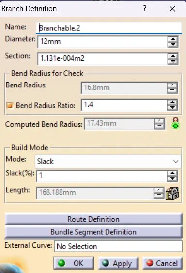
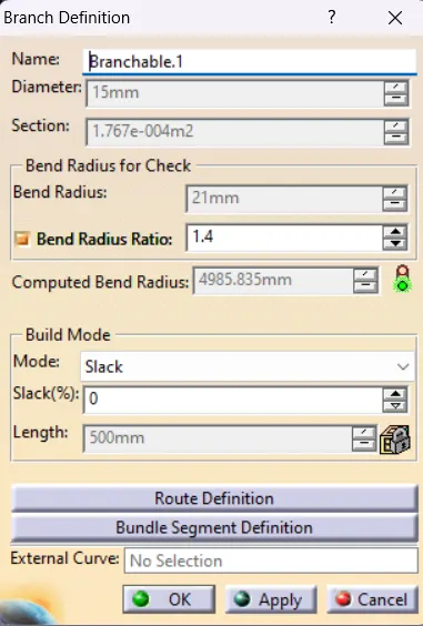
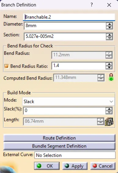
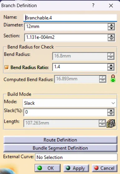
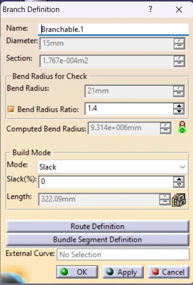
- The bundle diameters of 15mm, 12mm and 8mm, are assumed for various bundle segments. For all bundle segments, the bend ratio is 1.4 and the slack is zero percent.
- Select the Branch definition command and the following dilogue box pop up.
Step 6 :
After giving the details click on the Route Definition to select components for wiring harness routing.
Harness A
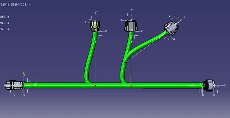
Inserting protective covering.
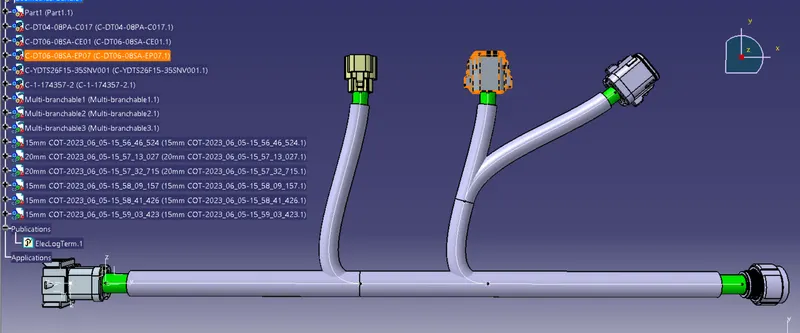
Harness B
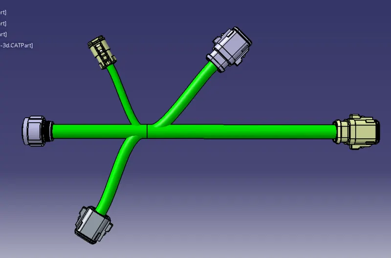
Inserting protective covering.
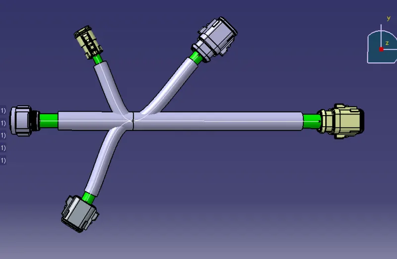
Step 7 : Inserting Both wiring harness A & B in to single file.

Step 8 : Using Connect Electrical Decive command connect two wiring harness.
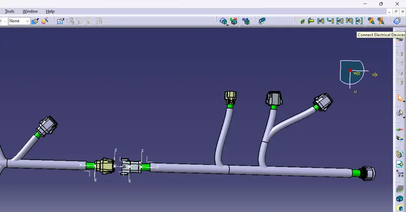
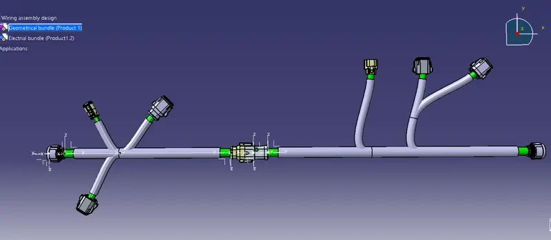
2. Checking the continuity of the bundle
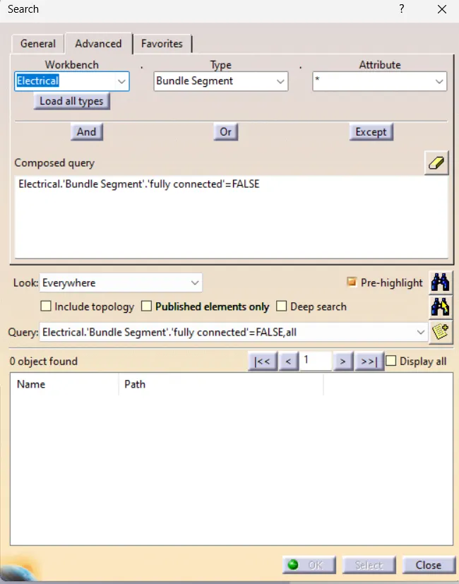
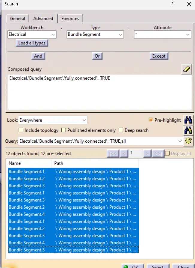
Goto Edit > Search > Advance > Select Electrical,Bundle segment,fully connected > set the condition to FALSE to get the list of bundles that are not connected.
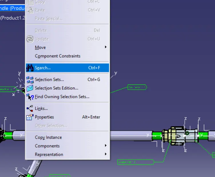
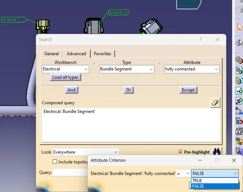
No bundle is found to be dis connected which means all the bundles are connected.
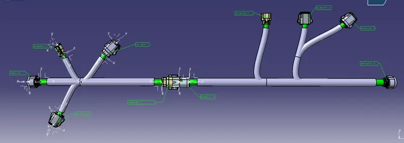
3. Step 9 : Adding annotation to all connectors
4. Checking for bundle warning
Harness A
Harness B
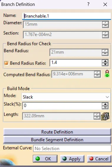
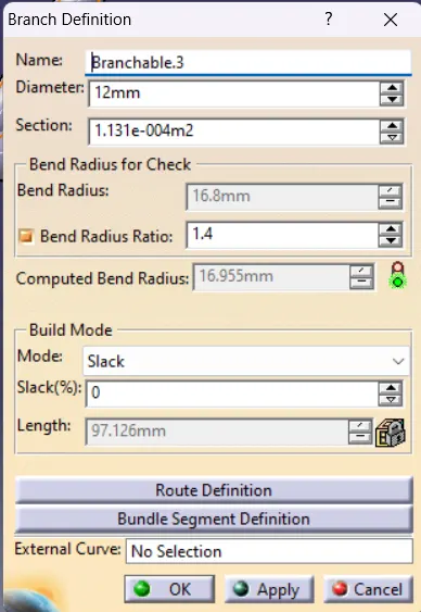
CONCLUSION
- Routed the harness layout in Electrical workbench.
- Checked the bundle Continuity.
- Added annotation to all connectors.
- Checked for the bundle warning.
- Generated CAT.part of harness assembly and convert is in. igs format.